05 February 2015 Lada.Online 461 040 5
The relay and fuse box is also called the mounting block or black box. If problems are identified in the car related to electrical equipment, first check the fuses and relays. If they burn out, we replace them with the same ones, but first we must determine the cause of the burnout.
Where are the fuses for the Lada Granta?
The fuse box is located near the driver's left foot. To open the lid, pull the lower left corner of the lid (No. 1) and release the left locking point, then the middle one (No. 2) and the two right locking points (No. 3 and 6). Then release the top points (No. 4 and 5) and remove the cover.
Installing the mounting block cover is done in the following order: first snap the right side of the cover, then the lower ones, and then the upper ones. Make sure that the fastening elements of the cover are aligned exactly with the metal fasteners.
There are symbols on the plastic cover of the mounting block that indicate what each fuse (F) and relay (K) does.
Operating principle of fuses
The principle of operation of the electrical equipment of the VAZ 2110 is not far from its great-grandfather’s VAZ 2101 - it is still the same single-wire circuit, where the role of the negative wire is played by the car body. The scheme is advantageous in that it allows you to reduce the number of conductors, but it also has its drawbacks. The main one is that in the absence of contact with the main mass on the body, almost all the electrical equipment of the car goes out.
Be that as it may, no one has repealed the laws of electrical engineering, and when a positively charged conductor and a negative one come into contact, without a load, a short circuit inevitably occurs. It leads to failure of electrical appliances on board, overheating of conductors, melting of insulation and can cause a fire. That's why you have to complicate your life with fuses.
Fuse and relay diagram
Old family
(until September 2020):
| Fuse | Current strength, A | Protected circuit |
| F1 | 15 | — Relay for turning on the engine cooling fan — Short circuit 2x2 — Controller (engine control unit) — Injectors — Ignition coil |
| F2 | 30 | Electric windows |
| F3 | 15 | Alarm |
| F4 | 20 | — Windshield wiper — Airbag |
| F5 | 7,5 | Ignition switch terminal 15 |
| F6 | 7,5 | Reversing light |
| F7 | 7,5 | — Canister valve — Mass air flow sensor — Oxygen sensor 1/2 — Speed sensor |
| F8 | 30 | Rear window defroster circuit |
| F9 | 5 | Side lights on starboard side |
| F10 | 5 | Side lights on the left side |
| F11 | 5 | Rear fog lights |
| F12 | 7,5 | Low beam on starboard side |
| F13 | 7,5 | Low beam on the left side |
| F14 | 10 | High beam on starboard side |
| F15 | 10 | High beam on the left side |
| F16 | 10 | Front fog lamp on starboard side |
| F17 | 10 | Front fog lamp on the left side |
| F18 | 15 | Heated front seats |
| F19 | 10 | ABS (Anti-lock Braking System) |
| F20 | 15 | — Horn — Trunk lock — Transmission — Cigarette lighter — Diagnostic connector |
| F21 | 15 | Electric fuel pump |
| F22 | 15 | central locking |
| F23 | 10 | Daytime Running Lights |
| F24 | 7,5 | Air conditioner |
| F25 | 10 | — Interior lighting — Brake light |
| F26 | 25 | Anti-lock braking system |
| F27 | — | Spare |
| F28 | — | Spare |
| F29 | — | Spare |
| F30 | — | Spare |
| F31 | 50 | Heated windshield |
| F32 | 30 | — Heater — Electric power steering |
Relay:
| Relay | Description |
| K1 | Heater fan relay. |
| K2 | Power window relay |
| K3 | Starter relay |
| K4 | Ignition switch terminal 15 relay |
| K5 | Turn signal and hazard warning relay |
| K6 | Wiper relay |
| K7 | High beam relay |
| K8 | Horn relay |
| K9 | Low beam relay |
| K10 | Heated rear window relay |
| K11 | Controller relay (engine control unit) |
| K12 | Electric fuel pump relay |
Lada Granta mounting block under the hood:
| F1, 50A | Electric power steering; |
| F2, 30A | Heater fan |
| F3, 60A | Generator |
| F4, 60A | Generator |
| F5, 30A | Dipped headlights. |
New family
(from September 2020):
Attention!
The relay and fuse diagram may differ depending on the configuration and production date of the vehicle. Current diagrams of the mounting block are presented in the operating manual for the date of manufacture of the vehicle ().
Let us remind you that you will find other useful instructions in the section Repair and operation of the Lada Granta.
Keywords: mounting block Lada Granta | Lada Granta torpedo
23
9
Found an error? Select it and press Ctrl+Enter..
How to change fuses
Replacing fuses is necessary when a device becomes inoperable. In most cases, they look for the cause of the breakdown, starting with the fuse, and only then, after making sure that the fuse has burned out, do they repair the circuit or device. It is prohibited to change a fuse without finding out the reasons for its failure; it is even more prohibited to replace a fuse with a higher rating. This can lead to failure of the entire circuit, device or series of devices, and can also lead to a fire in the wiring. Moreover, the use of bugs and homemade devices that replace the fuse is unacceptable.
Checking the fuse for functionality is as easy as shelling pears. It is enough to use a household multimeter to determine whether there is voltage on both legs of the fuse. If no current flows through it, the fuse has blown. You can also check the fuse by removing it from the mounting block with a plastic object and testing it with a multimeter.
In this way, you can quickly identify a malfunction and quickly eliminate it, knowing which fuse is responsible for the operation of which device. Good luck with the repair and don't confuse the fuses!
Diagnostics and fuse replacement
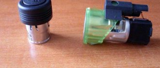
The connection diagram for the cigarette lighter on a VAZ of the “tenth” family involves the use of a protective element located in the vehicle interior.
The product is equipped with a thread made of low-melting metal; when a current with an increased rating passes, the jumper overheats and breaks the power circuit.
To restore the functionality of the equipment, it is necessary to find the fuse link, check its condition or replace it (if the jumper is damaged). VAZ designers provided for the use of blade-type fuses.
Where is
The cigarette lighter fuse on the VAZ-2112 is located in the mounting box installed at the bottom of the instrument panel. To access the protective elements, you need to press the plastic button, which will open the decorative shield. The fusible element responsible for the operation of the cigarette lighter and heating system fan is located in the 3rd position on the left in the bottom row of inserts. On VAZ-2112 cars there is no additional fuse element in the engine compartment that duplicates the protection of the passenger compartment junction box.
How to check
To check the protective element on cars with 8- or 16-valve engines, you must:
- Grab the protective element with special tweezers and pull it out of the seat.
- Inspect the part, which is equipped with a transparent plastic body with a special inspection slot. If a break in the jumper is visible, then no current will flow in the power supply circuit of electrical devices. In this case, you need to change the fuse. If the conductor is intact, then you will need to check the electrical wiring harnesses (in this case, the heater fan motor and the glove box lighting may work, for which the same protective element will be responsible). Before disassembling the instrument panel, check the circuits with a tester.
Where is it located and how to get a broken fuse for the VAZ 2110 cigarette lighter. We consider the most common fuse malfunctions and how to eliminate them.
What fuse can be replaced?
The manufacturer uses a protective element rated 25 A; the new part must have similar parameters. Spare inserts are located in slots on the top of the mounting block. If there is no fuse of the required rating, then find a part designed for a current of 10-15 A, which will ensure the operation of the heater fan, but it is prohibited to turn on the cigarette lighter. It is recommended to purchase a 25A fuse link from your local auto parts store.
If it's not the relay
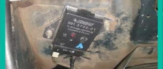
It also happens that the usual replacement of fuses does not help. They checked the wiring, replaced the relay, but still nothing works. In this case, it makes sense to pay attention to the condition of the steering column switch. There are several “sore” spots where the solder of the contacts holds weakly. Because of this, the turn signals may stop working. In this case, you need to remove it, find the faulty contacts and resolder them. There is nothing complicated here, the only important thing is the ability to handle a soldering iron. If the VAZ-2110 turn relay clicks when it is turned on, then the system is working. The steering column switch itself will cost you much more, so be careful when dismantling and installing it, try not to damage the connections and contacts.
What is the VAZ 2110-2112 fuse box?
It is not difficult to understand why they are needed. This protective element is found in almost any electrical circuit. It must protect the power source and electrical circuit of the VAZ-2110 from possible overloads and short circuits. Think about what would happen to your car if each of its individual electrical circuit elements were not protected?
The car's operation would be extremely unreliable. Any short circuit or overload in the electrical circuit of the VAZ-2110 would, at best, result in a simple failure of the vehicle, and in the worst case, failure of the battery and power supply circuit elements. That is why on VAZ cars fuses of the 2112 model, as in the top ten, are a key element of the electrical circuit.
Features of the VAZ 2110 fuse box
Structurally, they are a small transparent plate with two legs for electrical contact. The product itself contains a number with the rated current. This means, if the load in the protected circuit of the VAZ-2110 rises above the specified Ampere value, the fusible insert inside the fuse will melt and break the power circuit. Naturally, after operation, the spent element should be replaced.
The safety block consists of more than just protective elements. The main relays are also located there. They are the actuator. Under the influence of the electromagnetic force created by the control signal to the relay coil, an entire group of contacts can be closed and opened at once.
This is especially important for control lines. For example, the electronic components of the circuit are not able to independently turn on a large load, so they do this using an electromagnetic relay. The same applies to turning the ignition key. With one turn you turn on a huge number of devices and mechanisms independent from each other.
