To install any alarm system yourself, you should study its instructions in detail.
ATTENTION! A completely simple way to reduce fuel consumption has been found! Don't believe me? An auto mechanic with 15 years of experience also didn’t believe it until he tried it. And now he saves 35,000 rubles a year on gasoline! Read more"
Alarm systems from this company are perfect for installation on VAZ -2114 and VAZ -2115 cars
Before installing an alarm on a VAZ - 2115,2114 car, you need to have a good understanding of the car's structure, and also decide what to connect to the alarm.
Connecting the central lock
First you need to study in detail the connection diagram for the central locking on a VAZ car - 2115,2114. Finding it is not a problem by searching on the Internet.
The central locking control module is located on the left under the dashboard. Looking there, you will find six wires coming out of the module housing. To install the alarm, you must disconnect the blue and brown cords. As a result, we get a connection corresponding to the following diagram:
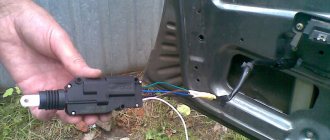
Before connecting the alarm, you should make sure that it is not a toggle switch installed on the driver's door, but a standard actuator with five outputs. Otherwise, you will need to install an actuator, which is quite problematic.
On VAZ -2115,2114 cars, the white wire, which is connected to the seventh terminal, is usually responsible for unlocking. If there are no connections at terminals 7 and 5, then the eighth terminal is connected to the brown cord. It is this cord that is responsible for unlocking in this case.
Terminals number five and six are responsible for locking the lock. This arrangement of contacts is typical for almost all blocks of the “ninth” series.
For some reason, none of the instructions for alarms ever indicate that installation requires the purchase of additional elements.
- Connection diagram for the ignition switch on the injection VAZ-2114: detailed pinout of wires
We will definitely need:
- Two to three 1N4001 diodes per Ampere
- One 1N5401 3 Ampere diode
- Two 4 or 5 Ampere diodes if there are no separate outputs for turn signals.
When installing a Starline alarm system, the task is greatly simplified, since significantly fewer additional parts are needed.
Principle of operation
How is the central locking system controlled on the VAZ-2114? The algorithm of the central locking operation is that a control pulse arrives at a certain point, as a result of which one relay with power contacts is activated. In one case the car is locked, in the other – vice versa. Central locking activators are connected to relay contact 30, and through closed contact 87, ground acts on both outputs of the activator. If one or another relay is triggered, then contact 30 will be connected to the positive, and as a result, temporary voltage will be supplied to the activator, which will set the rod in motion, which will either open or close the door.
Connection diagram
After carefully studying the alarm installation instructions, you can find the following connection diagram:
In this diagram, the designation X2 indicates a six-pin connector. It must be connected according to the diagram above. If you need to install an additional actuator, then it is better to use the diagram given in the instructions.
Now let's figure out how to connect the door sensors. For this purpose, there is a special wire in the connector marked X3.
Tapping into wires
Next to the driver's door, there are two wire harnesses running right along the floor. One of them has a cable coming from the parking brake and two wires to the turn signals. The second harness contains the door switch cable. This is where you need to start connecting. To do this, remove the sill trim along with the side panel. They are attached using self-tapping screws that must be unscrewed. Having done this, you can see the wiring harness shown in the photo:
This harness goes to the dashboard. We are interested in the door switch cable. If a 1N5401 diode is inserted into the wire break, the current should flow towards the limit switches. And the second diode 1N4001 is connected as shown in the figure.
The following figure shows the second harness:
At the same time, taps are made from the blue cables and the cords are pulled to the place where the alarm will be installed. And the handbrake wire is cut, and a 1N4001 diode is soldered into the cut with the cathode towards the switch.
- Do-it-yourself installation and connection of an alarm system to the VAZ-2114 central locking system
Connecting autorun
The VAZ-2114 models use an ignition switch with three terminals - 15 (blue wire), 30 (lilac) and 50 (red). Terminal 30 is connected to the battery. When you turn the key, blue wire 15 is connected to this terminal. The third terminal is responsible for the starter.
As it is written in the instructions, it is quite possible to power the alarm from contact 30, from which the lead is made. And the cable from connector X1, yellow, is connected to connector 15.
After all the actions taken, the connection of the tachometer remains. In this case, a loop antenna and a reading device are combined. Connector X3 has a gray-black outgoing wire. It is connected to the tachometer as shown in the VAZ dashboard diagram:
This will allow the alarm to control the speed. And at the very end we connect the ground from the main unit. This is a black cord from connector X3.
Settings
Only autorun functions can be configured. To activate programming mode:
- Disable security
- The ignition key is set to position 0.
- Then press the Valet key six times in the main block.
- Turn on the ignition
- After six beeps, use the same key to select the desired function, and use the key on the key fob to select the desired value.
The optimal settings for VAZ - 2115.2114 will be the following: function 12 - set to value 3, function 11 - value 4, function 9 - value 3. To select value 4, press and hold the third button until the melody is played. After playing, press it again.
To check the correct connections, perform the following steps:
- Disconnect the yellow cord from block A91 to terminal 15 for a while.
- The engine is started using the ignition key
At the same time, the alarm indicator should blink.
Tired of paying fines? There is an exit! Forget about fines from cameras! An absolutely legal new product - Traffic Police Camera Jammer, hides your license plates from the cameras that are installed in all cities. More details at the link.
- We install and connect fog lights on a VAZ-2114 with our own hands (video inside)
- Absolutely legal (Article 12.2);
- Hides from photo and video recording;
- Suitable for all cars;
- Works through the cigarette lighter connector;
- Does not cause interference to radios and cell phones.
Find out more Subscribe so you don't miss anything important Contents
In order to protect your car from theft, you can equip it with a device such as a central electronic lock. To do this, it is not at all necessary to contact a service or specialized workshop, because in fact, its installation is much simpler than it seems at first glance. In today's article we will talk about how to install central locking on a VAZ 2114 and how to avoid possible mistakes.
Alarm system with central locking VAZ 2114
Causes of malfunction
There are many reasons why the central locking on a VAZ-2114 stops working stably. All existing causes of malfunction can be divided into two subgroups: climatic effects and technical breakdown. In the first case, the lock begins to work unstably due to the influence of climate, that is, due to very low temperatures, as a result of which not only the lock, but also other systems may freeze.
Lock connection diagram
In order to be able to install central locking on VAZ cars, the manufacturer equipped them with a special BUBD control module. You can find it directly under the torpedo, on its left side. If this module is missing, it will simply not be possible to install the device, so before you buy an electronic lock, you should first find out whether the module is installed on the car.
Control module
The connectors of this module are equipped with 6 wires of different colors as standard. If you are installing an alarm system on a VAZ 2114, you will need to turn off brown and blue in order to get the following connection diagram:
Before you begin installing the lock, you should make sure that five-wire actuators are installed in the car doors. If it turns out that ordinary switches are installed instead of them, then it will not be possible to connect the alarm.
Another important point to remember is the need to purchase additional electronic components that are not included in the alarm kit.
These include:
- diodes 1N4001 for 1 Ampere - 3 pieces;
- three-amp diode 1N5401;
- any diode rated for a current of up to 5 Amps (only if there are no separate outputs for turn signals).
Diode wiring
Once these components have been purchased, you can begin connecting the alarm. To do this, you should carefully study the drawing with the connection plan included in the instructions (this diagram of the VAZ 2114 central lock is duplicated below) and carry out the entire installation procedure in accordance with it. So, in the diagram, the index X2 indicates the six-pin control connector (BUBD), which was mentioned at the beginning. This is where you should start connecting, guided by the same “native” circuit.
After the lock is connected, all that remains is to insert into the wires in order to connect the alarm to the door sensors.
Connecting door limit switches VAZ 2114
It is done in the following order:
- Remove the sill trim along with the side panel by unscrewing their fastening screws.
- In the exposed wiring harness, find the cable going to the door limit switches (it has a white and black color) and solder a 1N5401 diode into its gap so that the direction of possible current flow is only towards the limit switches.
- In the second wiring harness, find two blue cables, from which you should make taps (using a wire of the same cross-section) and stretch them to the location where the alarm is attached.
- Cut the handbrake wire and solder a 1N4001 diode into its gap with the cathode towards the limit switch.
Tapping into wires
If necessary, you can make an insertion into the wires even before connecting the alarm to the connectors - this will not affect the functionality of the electronic equipment in any way.
The next step is to connect autorun. To do this, you will need to power the alarm to terminal 30 of the ignition switch, and connect the yellow cable coming from connector X1 to its 15th connector (according to the connection diagram).
After the alarm is connected to the on-board power supply, you will need to connect it to the speed sensor by connecting the gray-black wire coming from connector X3 to the tachometer. After this, all that remains is to connect the black wire X3 to the ground connector in the main unit.
At this point, the installation of the central lock can be considered complete.
Replacing fuses on a VAZ 2114
When any problems are detected in the operation of the car’s electrical network and engine, be it the burnout of light bulbs or the failure of some electrical devices, the driver must first check the functionality of the fuses. The procedure is as follows:
- determine where the fuses are located on the VAZ 2114, which may have failed. To do this, look in the machine’s operating manual for a diagram of the location of the protective devices and determine whether they are located in the mounting block or under the dashboard in the area where the front passenger’s feet are located;
- when working with the car's electrical system, the negative contact of the battery must be disconnected;
- open the plastic latches holding the mounting block cover;
- remove the plastic tweezers from the mount in the upper right part of the block; they can be red, transparent or yellow;
- take the protective device, the circuit of which is supposed to be broken, by the body with tweezers and pull out the fuse;
- There are rules, developed by operating experience, on how to check the fuse. First of all, it is necessary to visually determine whether the fuse-link inside the case has burned out or whether the charger is in good condition;
- if the destruction of the insert cannot be visually determined, it is necessary to check the protective device using a device;
- If confirmation is received that the fuse has blown, it must be replaced with a functional one. The price for a VAZ 2114 fuse box on the automotive market is about 2,000 rubles, and a set of separate chargers of this type will cost 150 -250 rubles.
It is strictly forbidden to install home-made devices or jumpers in place of failed chargers, as well as fuses with a different rated insert current. A short circuit or fire may occur.
When working with the mounting block, do not use metal screwdrivers or other metal tools, this can lead to a short circuit and failure of the mounting tracks of the block.
We invite you to watch this useful video:
Settings
After the alarm system on the VAZ 2114 is fully connected, its final configuration should be performed.
It is carried out as follows:
- Disable security.
- Set the ignition key in the lock to o.
- Press the button labeled Valet 6 times in a row.
- After the step marked “3”, immediately turn on the ignition (6 beeps should sound).
- Using the Valet button, select the required function (their list is given in the table below). To set it to the required value, press the corresponding key on the alarm key fob.
In this case, the most optimal (recommended) settings will be the following:
- for function 12 - value 3;
- for function 11 - value 4;
- for function 9 - value 3.
You can check whether the alarm is connected and configured correctly as follows:
- Disconnect the yellow cord coming out of block A91 from terminal 15 of the ignition switch.
- Turn the ignition key and start the engine.
- Pay attention to the alarm LED - if connected correctly, it should blink continuously.
The last thing I would like to talk about today is the importance of correctly connecting the tachometer, which directly affects the operation of the autostart.
To avoid errors, it is recommended to make this connection strictly in the following order:
- connect the red wire from the BUBD connector to the positive 12 volt terminal;
- connect the black wire of the 18-pin connector to the vehicle ground;
- Connect the gray-black wire of the same connector to the wire coming from the tachometer.
If you then turn on the ignition, then if the tachometer is connected correctly, the alarm indicator will begin to blink evenly.
Purpose of fuses
What fuses are on the VAZ 2114? The electrical circuit of this car is designed in such a way that in front of all the main electrical units there are chargers located in the fuse box.
VAZ 2114 fuse diagram
The connection diagram of these protective devices is shown in the figure.
- F1 - rated insert current 10 A - protects the fog lamps located at the rear.
- F2 - with a current of 10 A - these are left and right turn lights, an emergency warning light, a relay-breaker for turn lights and emergency lights.
- F3 - with a current of 7.5 A - protection of light bulbs in the cabin and trunk, trip computer circuits, ignition and brake lights, "Check engine" warning light.
- F4 - with a current of 20 A - protects switches located in the heating circuit of the trunk door glass and heating elements of this glass, “carrying” contacts.
- F5 - with a current of 20 A - protects the horn circuit and its switch, as well as the electric motor of the cooling system fan.
- F6 - with a current of 30 A - this is a circuit of electric windows and their switches with contacts.
- F7 - with a current of 30 A - a protective device for three electrical units - a heater, a windshield washer and a headlight cleaner. In addition, there is also a cigarette lighter, glove compartment lighting and winding for the heating switch for the trunk door glass.
- F8 - with a current of 7.5 A - is protection for the right fog light bulb located in front.
- F9 - with a current of 7.5 A - this is protection for the left fog light bulb located in front.
- F10 - with a current of 7.5 A - protects the indicator lights on the left side, the license plate number, the engine compartment light, the dashboard lights and switches with heating levers, as well as the indicator lights for the size.
- F11 - with a current of 7.5 A - protects the right-side headlight bulbs.
- F12 - with a current of 7.5 A - a protective device for the right low beam headlight bulb.
- F13 - with a current of 7.5 A - a protective device for the left low beam headlight bulb.
- F14 - with a current of 7.5 A - protects the left high beam headlight and the blue high beam warning light.
- F15 - with a current of 7.5 A - protects the right high beam headlight.
- F16 - with a current of 15 A - protects the light bulbs and the turn switch and hazard warning lights, the white reverse light, the power supply of the instrument cluster, the trip computer, the generator winding (at startup), the lights indicating low oil pressure, brake fluid and parking brake, battery discharge.
Useful video
You can glean additional useful information from the video below:
Published July 05, 2019
This review discusses how to connect an alarm system to the central locking of the following cars: VAZ-21099, as well as 2110 and 2115. There are three standard connection schemes: for central locking controlled by negative polarity, positive and variable. But different cars have their own nuances. Sometimes it is necessary to add a fuse to the “+12 Volt” wire, sometimes, on the contrary, this is not required. VAZ locks, in turn, belong to the simplest type, the first. But the standard scheme published on the Internet is not suitable for them.
Experts' opinions
Many experts who have encountered the problem that the central locking on a VAZ-2114 does not work argue that all problems with the device should be divided into certain categories. Below we will look at each of them.
- Complete device failure.
- Partial lock failure.
- Operation malfunctions due to mechanical, electrical or other defects.
If a problem occurs with the central locking, the car owner must independently determine which of the above categories the breakdown falls into. Therefore, repairing a fault should not begin with disassembling a particular unit - it is enough to conduct a thorough diagnosis of the equipment. Thanks to the diagnostics carried out, the car owner will not only reduce the time spent searching and solving the problem, but will also reduce the monetary costs of repairs.
Features of the VAZ central lock
Everyone knows that the Lada models listed here use central locking controlled by negative polarity. This literally means the following: we apply “0 Volt” to one wire - all locks close. We apply the same voltage to the other wire (second) - they unlock. This is done in many European cars. What does it mean to “supply “0 Volt”? This means connecting the wire to ground.
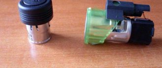
Central locking control unit connector
The central locking control unit has the following wiring:
- Black wire – ground (connected all the time);
- Pink – power supply “+12V” (built-in fuse is used);
- Yellow, red - connected to the actuators in the doors (these wires are not connected to the signaling system!);
- Brown, white - control wires, just those that have already been mentioned.
Let's look at the central locking connection diagram, which is implemented “from the factory”:
Standard connection diagram for central locking
First, we may decide that the triangular connector (labeled “C”) is suitable for our purposes, since it contains control contacts. But please note that the standard circuit uses a microswitch located in the driver's door. We will break two wires coming from this switch, and the relays built into the alarm unit will be connected to the breaks. Other options are excluded.
The central locking does not work - we are looking for the reason!
Central locking + alarm testing
Quite often, the central locking system is supplemented with an alarm system, so at the first sign of incorrect operation, you should check the “signaling system”; it is often the cause of all the troubles. If the locks do not work “from the key fob,” try closing them with a key, that is, by placing the key in the keyhole.
If the central locking does not work only with the key fob, but everything is opened with the key, you should check the battery, as well as other control circuits of the alarm.
The central lock does not close or open, it does not work completely
If during the test the central locking does not work correctly or is unstable, both manually and remotely, in order to make a “verdict” it is necessary to clarify some nuances. For example, where did the failure occur, are any clicks heard, or do the door lock buttons move when trying to lock the doors. You should check the central locking fuse, as well as other electrical circuits that may be involved in this.
The fuses are ok, but the central locking does not work
If the fuses are normal, but you still don’t know why the central locking system does not work, you should continue the diagnostics in order to understand the reason.
But the problem may actually lie in the locking devices, which could simply fail due to a lack of voltage on the driver's door activators. This happens due to poor contact, oxidation of terminals, and also in case of broken wires. In this case, the driver's door drive cannot send the incoming signal that goes from the remote control to the other doors of the vehicle. This phenomenon occurs in cases where the driver's door actuator limit switch is faulty. The control signal is not detected.
Repairing the central locking should begin with diagnosing the power supply, as well as the control signal. A visual check of the system wiring is necessary to check for poor connections or breaks. It is also imperative to check the limit switch installed inside the drive.
Central locking malfunctions: spontaneous locking or unlocking of doors
It is a common occurrence that after locking the central locking door locks “with a button”, after some time they open spontaneously. That is, the opening occurs even without a signal from the remote control. The reason for this phenomenon may be improper fixation of the rod fasteners, which are located between the drive and the driver's door lock mechanism. Thus, a violation of the opening and closing of doors occurs.
Let's make the alarm system and central locking together
Any modern alarm unit is equipped with two relays connected to the central locking control unit. One relay is opening, the second is locking, and the circuit in the general case looks like this:
Control of central locking by supply of “mass”
In our case, the green and white cords coming from the signaling unit will be required, as indicated in the diagram. However, they will not be the only ones needed. We will connect the relay contacts to breaks in the standard wiring. This means there will be not 2, but 4 cords.
Connection diagram for VAZ central locker
Take another look at the diagram published in the first chapter. We will connect the relay to the gap in the white and brown wires going from the microswitch to the central lock control unit. And it is obvious that it is easier to break these wires near the 8-pin connector. The same one shown at the beginning.
To avoid any questions, we will show you what should happen as a result:
Connection diagram, central lock VAZ
The common contacts are connected to the wires coming out of the microphone. The white cord continues with the brown wire coming from the door, and so on. Normally closed contacts are also used, along with normally open ones. These are the features of connecting to the VAZ central locking system.
An approximate sequence of actions performed by the installer:
- Make and lay a 4-core cable running from the signaling unit to the 8-pin connector;
- Connect the cable on the side of the alarm unit (see the last diagram);
- Near the 8-pin connector, disconnect the white and brown wires coming from the microswitch (pins 5 and 7). The main thing is not to confuse them with the wires going to the triangular connector “C”;
- Make connections to the broken wires, white and brown. That's all.
We have given this sequence to emphasize once again that the relays are switched on between the microphone and the central lock control unit. There is no need to connect any additional devices. As a result, the alarm system will be able to control the state of the locks.
Remember that installation is performed by removing the negative terminal from the battery.
All wires added to the car structure must be protected (use heat-resistant tubes or electrical tape). Twisting is not the worst method to connect two wires. But it's even better to use soldering.
An interesting nuance from practice
It would seem that if a person has experience working with electrical equipment, he can do everything according to the instructions given. As a result, if no mistakes are made, you may encounter an interesting phenomenon. Instead of closing, there will be a short-term locking followed by opening. And vice versa. What to do in this case?
Take a look at what exactly may be present in some of the configurations:
Cheaper - no driver actuator
The driver's door may not have an actuator. And then, it is useless to connect the signaling system to the control unit. There is no actuator, which means there is no one to close or open the door and move the microphone lever. Let's say the locks are closed, and then we remove ground from the brown wire and we get the following: the white wire is on ground, unlocking occurs.
We note the following: installation can only be carried out when you are sure that there is an actuator in the driver's door.
There were configurations where only a microswitch was installed. There is no need for arrogance here - adding an actuator will be difficult, since standard wiring must go to it. As you understand, it may not be available from the factory. And it’s unclear what to do then.
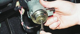
There remains one unanswered question - where exactly the central locking control unit is located. In these VAZ models, if there is a central locking system, then there is also a control unit. And it is located under the torpedo cover, next to the driver, on the right:
VAZ-2110, BU TsZ
We remove the “beard” of the torpedo and look at what is on the upper right. On the same plane with the radio connector there are two boxes attached - the one we need, as well as the immobilizer (if there is one).
We would be lying if we did not say that in reality there is another option for installing the alarm. Standardly, only two power cables go to the actuators. Having a power outlet equipped with a fuse, these cables are connected directly to the alarm relay. This option, as you might guess, is not recommended. Imagine what would happen if the alarm system broke. The central lock must remain, but in this case this will not be done. Happy connection!
Common node faults
Often the central locking of the VAZ-2114 is controlled incorrectly due to the fact that the contact pairs are closed with a delay. A common reason for this is a violation of the adjustment of the thrust located between the gearmotor and the lock button, or its jamming. Simply put, when the button is pressed, the position of the rod does not allow the contact pairs of the drive to be completely closed.
The door on the driver's side may be locked, while the others will remain open due to the fact that the contacts of the control unit are not fully closed. This malfunction is purely mechanical in nature, and to eliminate it, it is enough to adjust the rod or the free play of the button in case it gets stuck.
In addition, such a problem can be caused by a malfunction of the VAZ-2114 central locking relay. In this case, you will have to replace the failed element.
In the case when the VAZ-2114 central locking completely stops responding to commands given by the driver, it is worth moving on to checking the electrical part of this unit. It is possible that this behavior of the system is caused by a blown fuse. Note that it can fail not only in the event of a short circuit, but also from constant overloads caused by the heavy movement of the core, or a violation of the adjustment of the rods.
Quite often, the reason why the VAZ-2114 central lock does not work is a violation of the integrity of the electrical wiring supplying power to it. The wires in the driver's door of a vehicle almost always break because it opens and closes more often than others. You can determine the damaged section of the wire using a multimeter. Less often than not, the control unit fails. In this case, the entire system either completely stops working or performs its functions incorrectly.
To prevent module malfunctions, it is necessary to pay attention to the condition of the activator, since its contacts can oxidize or burn, causing malfunctions. Periodic cleaning will significantly extend the life of the module.
Drivers often wonder why the central locking on Kalina, VAZ 2114 and Ford Focus 2 does not work. This is a fairly common problem. There can be quite a few reasons for its occurrence. Some of them are common to all these models. Other problem areas are quite individual. The problem can be caused by either electronic or mechanical faults. To find the cause, you need to check all the options. Sometimes there may be several breakdowns.
Therefore, if you come across a malfunction, you should continue your search; perhaps this is not the only reason. As a rule, even an inexperienced driver can quickly fix a breakdown.
Why doesn't the central locking work on Kalina, VAZ 2114 and Ford Focus 2? To answer this question, you need to carefully review all the details and elements related to this design. Before starting work, think about what has happened to the car over the past few days. Some actions can indirectly lead to damage to the lock. Be sure to check all connections. This will help you find the problem as quickly as possible.