10/29/2020 5,372 Fuses
Author: Victor
All vehicles have a block in which protective inserts for the electrical circuit are located. VAZ 21214 fuses on the Niva injector are installed in several places. In addition, the block diagram has its own nuances associated with the great age of the car design.
[Hide]
Where are the fuse and relay boxes located?
The electrical equipment system, electrical wiring and arrangement of safety blocks on the Niva 21214 and the modern Chevrolet Niva VAZ 2131 are identical. The electrical circuit of these machines has a main mounting block installed under the lower edge of the instrument panel casing in the area of the driver's left foot. An additional one is located under the main block.
A little to the left and below there is another additional block, in which inserts are installed that are responsible for the operation of the components of the fuel injection system. In addition to the fuses, there is a separate relay for controlling the wiper operation parameters and a set of relays for the engine control system.
When installing an injection engine on a car with an old wiring diagram, the designers had to install additional switching boxes.
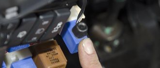
One of these blocks is located on the left side of the body near the main fuse box. Since the unit is installed in close proximity to the driver’s left foot, it is covered with a special protective plastic casing. The casing is fixed with two self-tapping screws for a Phillips screwdriver. The block itself contains a diagnostic connector and four fuses responsible for the operation of the engine and cooling system.
Block with cover removed
The relay responsible for turning on the engine starter can be installed separately in the engine compartment or next to the relay block. When installed under the hood, it is mounted on the compartment shield next to the brake fluid reservoir.
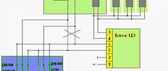
Fuse connection diagram
| Number | power A | Purpose of the fuse |
| Fuse box located under the control panel | ||
| 1 | 16 | Heater fan - electric motor Headlight cleaner and headlight wiper motor in all wiper positions except the original Heated rear window - power relay (winding) Rear window cleaner and washer Windshield washer |
| 2 | 8 | Turn signal, turn signal and hazard warning signal breaker relay - turn signal mode Reversing lights Windshield wiper (gear motor and relay) Generator - field winding Warning lights: brake fluid level, oil pressure, carburetor choke, parking brake Coolant temperature gauge Gauge fuel level, reserve indicator lamp Voltmeter |
| 3 | 8 | High beam - left headlight, control panel warning lamp |
| 4 | 8 | High beam - right headlight |
| 5 | 8 | Low beam - left headlight |
| 6 | 8 | Low beam - right headlight |
| 7 | 8 | |
| 8 | 8 | Side lights: right front and left rear Lights: instrument panel, cigarette lighter, switches and interior switches |
| 9 | 16 | Turn signal and relay hazard warning light interrupter Hazard warning light indicator Heated rear window: heating element and switching relay (contacts) |
| 10 | 16 | Horn Light socket Interior lighting Brake light - tail lights |
| 12 (13) | 8 | Fog lights - rear |
| 16 (15) | 16 | Cigarette lighter |
| For VAZ-21214, the injection system fuses are located in a separate block on the left side under the instrument panel. | ||
| 1 | 30 | Cooling fans |
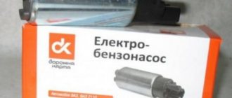
| 2 | 15 | Electric fuel pump |
| 3 | 15 | Control block |
| 4 | 15 | Main injection relay |
We hope that this information was useful to you if you encounter problems with the electrical equipment of NIVA.
We will be glad to see you in the Niva owners club on our forum. Any car is equipped with fuse blocks (FBs), which are responsible for the safety of electrical circuits. Their location differs not only depending on the make of the car. Even in models of the same manufacturer that are close in year of production, they can be placed in different patterns. However, in some cases the location may coincide completely.
The main power supply in these models is located under the lower edge of the instrument panel protection. Additional fuses in Niva 21214 for the injector are located to the left. This block is responsible for controlling fuel injection. There are also relays for monitoring the operation of the wipers and a set responsible for the motion control system.
Another fuse box is installed in the body to the left of the main one. They are responsible for the cooling system and how the engine works. There is also a diagnostic connector. The relay that controls the starter is located either next to the main power supply, or under the hood next to the brake fluid reservoir.
Car owners are well aware that the VAZ 21214, 21213 (Niva) fuse box is a critical detail that requires detailed study. Knowledge of the electrical circuit allows you to avoid many problems and carry out timely diagnosis of breakdowns. Since the family has existed for many decades, it has managed to go through a number of radical changes - the transition from carburetor to injection engines, for example. This did not entail a radical change in the location and content of the mounting blocks, of which there are two in the cabin and one under the hood.
New additional block
Old additional block
Current (amps)
What is he responsible for?
Current (amps)
What is he responsible for?
Turn signal lamps, relay-breaker for turn signals and emergency lights
Daytime running light relay, Daytime running light bulbs
Rear fog lights and their relay
Fog lights and their relays
The Niva with fuel injection has today almost completely replaced the carburetor models of the family. With the transition to a new injection system, the manufacturer tried to minimize the inconvenience for the car owner and not radically change the location of the mounting blocks, as well as their filling with protective elements. Traditionally, there are two of them in the cabin. Another one, in the back, is responsible for controlling the engine.
Modern AvtoVAZ SUVs use injection power units. If a malfunction is detected in the electrical equipment of the car, you should first check the serviceability of the fuses and relays. Next, we will show where the mounting block is located (fuse box or black box), as well as the location of the elements inside it.
1 — engine control system fuse box; 2 — windshield wiper relay; 3 — fuse blocks; 4 — relay block of the engine control system.
The fourth relay block is located above the gas pedal.
| №1 | Rear fog lamp relay |
| №2 | Rear window heating relay |
| №3 | Low beam relay |
| №4 | High beam relay |
The fuse block (hereinafter referred to as the fuse block), unlike traditional models of the domestic automobile industry, is located in the vehicle interior. In particular, it is located on the driver's side under the steering wheel. If any electrical circuit element in a car stops working (lamps, interior lights, heater, power windows), then car owners first check the power supply elements. As a rule, the problem is resolved by replacing the fuse.
What does the power supply circuit itself look like? This question may be of interest to Niva owners. Below we will look at the electrical circuit of the unit with a description of all the components responsible for the operation of certain devices in the car.
In accordance with the diagram, we will consider the meaning of the BP elements. This electrical circuit is universal for all Niva cars.
Also interesting: Chevrolet Niva idle speed sensor
It should also be noted that in VAZ 21214 injector cars there is another power supply unit with injection system components. It is located separately from the main power supply on the left side under the steering wheel.
In the case of the first described power supply unit, if the elements of the device begin to fail, this will in no way threaten the performance of the car, of course, with the exception of breakdowns of some components. However, in the case of the second power supply, if at least one component shorts out and does not work, the VAZ 21214 injector engine will not start.
The fuses in VAZ cars, as well as in the Niva, are located directly inside the car; they are covered by a shield, usually on the dashboard.
This allows, if necessary, to disassemble and carry out repairs using available tools. This approach is especially helpful in cold weather - there is no need to carry out repairs outside, and the cost of self-replacement will be much lower than in a service center.
The above circuit includes components such as relays and fuses. The mounting block includes the following elements presented in the table.
| Element designation | Protected Circuits |
| Relay | |
| K1 | Responsible for the light bulbs inside |
| K2 | Proper operation of windshield wipers and wipers. |
| K3 | Device for designating sensors indicating the direction of turns. |
| K4, K5 | Low and high beam blocks. |
| K6, K7 | Connection of non-fixed assets. |
| K7 | Rear window heating unit. |
| Circuit breakers | |
| F1 | Signal lights, license plate lights, trunk and glove compartment lights, 5A. |
| F2 | Low beam left side lighting, 7.5A. |
| F3 | Left headlights, high beam, 10A. |
| F4 | Fog lighting, left headlights, 10A. |
| F5 | Fuse for power windows, 30A. |
| F6 | For connecting portable lighting, 15A. |
| F7 | The unit responsible for the engine cooling fan, as well as for triggering the sound signal, 20A. |
| F8 | Heated rear windows, 20A. |
| F9 | Recirculation unit, cleaning headlights, windshield; 20A. |
| F10 | Additional, maybe for battery charging. |
| F11 | Side light right, 5A. |
| F12 | Right headlight, low beam, 7.5A. |
| Ф13,14 | Fog lighting, right headlights, 10A. |
| F15 | Fuse for heated seats and closing the luggage compartment, 20A. |
| F16 | Alarm system operation, 10A. |
| F17 | Internal light, serviceability of the on-board computer, 7.5A. |
| F18 | Responsible for the cigarette lighter, light in the glove compartment, 25A. |
| F19 | Serviceability of central locking, brake light, reverse lights, generator windings, 10A. |
| F20 | Rear fog light, 7.5A. |
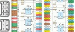
Designation and electrical diagram of the main and additional power supply
The designations and explanations of the fuses of the main and additional units are printed on the surfaces of the covers.
Diagram of the main and additional blocks
Description of the fuses in the upper main section of the VAZ 212214 Niva injector.
| Number on the diagram | Rated current, A | Purpose |
| PR01 | 16 | Heater fan motor, front glass fluid supply system, rear wiper motor |
| PR02 | 8 | Front wiper, direction indicators (with relay), switch block under the steering wheel, instrument cluster instruments and lamps, reverse indicator lamps |
| PR03 | 8 | High beam in the left headlight and high beam indicator lamp in the instrument cluster |
| PR04 | 8 | High beam for right headlight |
| PR05 | 8 | Low beam left |
| PR06 | 8 | Same as on the right |
| PR07 | 8 | Left side dimensions, registration plate illumination, dimensions indication on the instrument cluster |
| PR08 | 8 | Right dimensions and illumination of control devices |
| PR09 | 8 | Hazard warning relay circuit and activation button, rear defogger system |
| PR10 | 8 | Horn, interior lighting and brake lights (all three) |
Overview of the fuses of the small additional block located under the main one.
| Number on the diagram | Rated current, A | Purpose |
| PR11 and 12 | Positions are reserved | To store two 8 amp inserts |
| PR13 | 8 | Turning on the rear fog lamps |
| PR14 | 16 | Cigarette lighter |
| PR15 and 16 | Positions are reserved | For storing two inserts - 16 and 8 amps |
On Niva Urban 4x4 the fuse ratings have been slightly changed. The changed positions are listed below, the remaining chains and denominations remain the same.
| Number on the diagram | Rated current, A | Purpose |
| PR01 | 16 | Heater fan, start of heated rear window, drives for all windshield wipers and washer. Additionally (optional), this insert displays circuits for electric drives of windows and mirrors. |
| PR02 | 8 or 16 | Higher rating - heater fan and compressor (optional change - only for cars with air conditioning) |
| PR09 | 16 | Heated glass (there may be an additional option - heated mirrors) |
| PR10 | 16 | Horn, brake lights and interior lighting |
| PR11 | 8 | Alarm |
| PR12 | 8 | Daytime running light system |
| PR15 | 16 | Heater fan (not on all cars - only with air conditioning) |
The video by Vladimir Zhupikov shows a copy of Niva 21214 Urban with a heater fuse in position PR15.
Engine control system fuses
Purpose and parameters of fuses in the block (from left to right):
- 1 — ensuring the start of the electric motor of the right fan (rated 30 A);
- 2 — similar fuse-link for the left fan;
- 3 - fan relay, as well as the injection system control unit, control of injection nozzles and ignition coil (rated 15 A);
- 4 - system for reducing gas toxicity - heating of lambda probes, fuel vapor trap valve and sensor for measuring the volume of air entering the engine (rated 15 A);
- 5 - diagnostic connector for monitoring the operating parameters of the injection system.
On some VAZ 21214 with an ABS system, a fuse block with 7 inserts is installed.
Block Niva Urban
Assignment of fuses (numbering starts from the door opening).
| Number | Rated current, A | Purpose |
| PR01 | 15 | Sensors on the engine, gasoline vapor trap, starter |
| PR02 | 15 | Fans, engine operation systems (control unit, ignition, injectors) |
| PR03 | 30 | Fan starting system |
| PR04 | 15 | Gasoline pump |
| PR05 | 5 | ABS unit |
| PR06 | 40 | Likewise |
| PR07 | 25 | Likewise |
Engine Control Relay Box
The engine control relay diagram is shown in the photo.
Engine control relay
The block contains the following relays (from left to right):
- 1 — ignition activation;
- 2 - main relay, which serves to start all engine systems;
- 3 — starting the right fan on the radiator;
- 4 — start of the left fan;
- 5 — ensuring the operation of the fuel pump;
- 6 - safety element of the fuel pump power supply circuit with a rating of 15 A.
Relay block diagram above the gas pedal
The diagram of the block with the relay, which is located slightly deep in the instrument panel and is responsible for lighting the car, is shown in the photo.
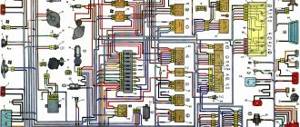
Wiring diagram
The purpose of the relay in the block (from left to right) is given in the table.
| Position | Purpose |
| 01 | Rear fog lamps |
| 02 | Heated glass on the rear door |
| 03 | Low beam |
| 04 | High beam |
Video “Replacing fuses on Niva 4x4”
Author Alexander Belousov is looking for the reason for the constant failure of fan fuses on his VAZ 21214.
Cars considered: Niva 2121, Niva 21213, Niva 21214 carburetor, injector (another name for VAZ 2121, VAZ 21213, VAZ 21214, Niva 4?4)
The main fuse box is located in the passenger compartment under the dashboard, to the left of the steering wheel.
| Relay no. | Decoding |
| 1 | Engine control system fuse box |
| 2 | Windshield wiper relay |
| 3 | Fuse blocks |
| 4 | Engine control relay block |
Replacing the block
In case of burnout or mechanical damage, it is necessary to repair the unit by replacing its components or the entire assembly.
To replace the main unit, follow these steps:
- Disconnect the battery from the on-board network.
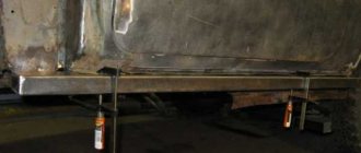
- Remove the box cover and unscrew the two 8 mm nuts securing the block. Then you need to pull the box towards you and remove it from the fastening studs.
- Write down the markings and position of the wires on the old unit.
- Disconnect the cables from the plugs of the old unit and connect them in the same sequence on the new one.
- Check fuse ratings and wire installation.
- Secure the replaced block with nuts.
- Connect power to the on-board network and check the functionality of the circuits.
The photo shows some stages of dismantling the block.
Unscrewing fasteners
Removal from studs
Disconnecting the wiring plugs
Other fuse or relay blocks on the VAZ 21214 are replaced in the same way.
Replacing fuses
If any electrical circuit in the vehicle fails, the condition of the fuse must be checked.
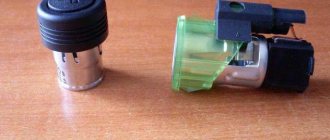
If it is necessary to replace parts, it should be taken into account that the VAZ 21214 fuses on the Niva injector belong to two different types:
- in the main block there are cylindrical inserts (inherited from the Zhiguli);
- and in the injection system blocks - modern, knife type.
Therefore, when you go on a trip, you need to take with you spare inserts of different types.
If, for example, a cigarette lighter fails on the road, you must:
- Turn off the ignition.
- Open the cover of the additional unit.
- Visually check the condition of the PR14 16 ampere fuse, which is responsible for the cigarette lighter circuit.
- Remove the burnt insert with your fingers and replace it with a spare one taken from the reserve socket PR15. It is prohibited to use homemade inserts, as they are not able to protect the circuit from overloads. The consequence of this may be overheating of the elements and fire.
- Check the functionality of the circuit. If the insert immediately burns out again, then the reason lies in damage to the wiring, which must be carefully checked.
The remaining fuses and relays on the VAZ 21214 are changed using a similar scheme.
VAZ Niva fuse diagram for injector
In case of burnout or mechanical damage, it is necessary to repair the unit by replacing its components or the entire assembly.
To replace the main unit, follow these steps:
- Disconnect the battery from the on-board network.
- Remove the box cover and unscrew the two 8 mm nuts securing the block. Then you need to pull the box towards you and remove it from the fastening studs.
- Write down the markings and position of the wires on the old unit.
- Disconnect the cables from the plugs of the old unit and connect them in the same sequence on the new one.
- Check fuse ratings and wire installation.
- Secure the replaced block with nuts.
- Connect power to the on-board network and check the functionality of the circuits.
The photo shows some stages of dismantling the block.
Unscrewing the fasteners Removing from the studs Disconnecting the wiring plugs
https://www.youtube.com/watch?v=YGm_VBSFWAc
Other fuse or relay blocks on the VAZ 21214 are replaced in the same way.
If any electrical circuit in the vehicle fails, the condition of the fuse must be checked.
If it is necessary to replace parts, it should be taken into account that the VAZ 21214 fuses on the Niva injector belong to two different types:
- in the main block there are cylindrical inserts (inherited from the Zhiguli);
- and in the injection system blocks - modern, knife type.
Therefore, when you go on a trip, you need to take with you spare inserts of different types.
If, for example, a cigarette lighter fails on the road, you must:
- Turn off the ignition.
- Open the cover of the additional unit.
- Visually check the condition of the PR14 16 ampere fuse, which is responsible for the cigarette lighter circuit.
- Remove the burnt insert with your fingers and replace it with a spare one taken from the reserve socket PR15. It is prohibited to use homemade inserts, as they are not able to protect the circuit from overloads. The consequence of this may be overheating of the elements and fire.
- Check the functionality of the circuit. If the insert immediately burns out again, then the reason lies in damage to the wiring, which must be carefully checked.
The remaining fuses and relays on the VAZ 21214 are changed using a similar scheme.
Loading …
Loading …
The most common elements to be replaced in Niva-2121.
- F1 (16) - jumper for the electric motor of the heating fan, turning the heating and rear view glass washer on and off.
- F2(8) - steering switch for front window wiper, alarm system switch, breaker relay, rear lighting switch, dashboard sensors: coolant temperature sensor, fuel level sensor, tachometer, indicator lights - turns, differential locks, emergency brake system , oil pressure, fuel quantity, battery charge.
- F10(16) – signals, lighting, brake lights.
- Rear light.
- Rear heated window switch.
- Low beam.
- High beam.
Above this panel there is a rotary relay and an alarm.
In order to replace a blown electrical fuse, special knowledge and skills are not required. Everything is very simple.
Below we will look at the process of replacing the power supply with your own hands. To replace, you will need a new power supply and a socket head set to “8”.
- First, open the hood and disconnect the battery.
- Now, under the instrument panel, find your power supplies. Using an “8” socket wrench, unscrew the two main nuts.
- Having done this, pry up the power supply and remove them from the studs.
- If you are replacing an old component with a new one, you must mark all the wires before doing so. Or take a new power supply unit and insert the wires from the old unit into it one by one. To remove the idle wires, pull them by their plugs.
- To check the functionality of the new power supply, reconnect the battery.
This completes the process of replacing the power supply.
Note! There is a lot of advice on the Internet about what to do if one of the PSU components fails. In particular, some car owners make mistakes that can subsequently negatively affect the operation of the electrical wiring as a whole. When a fuse fails, some drivers simply take a regular wire and bend it, inserting both ends into the power supply in place of the broken component.
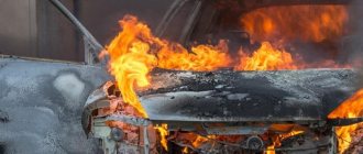
They claim that there is nothing wrong with this and that it is possible to travel like this temporarily. Please note that such homemade solutions can not only negatively affect the operation of the power supply, but also the entire electrical circuit as a whole. One short circuit can not only damage the power supply itself, but also provoke a fire, and, accordingly, a fire.
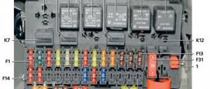
Each of the fuses (FC) is responsible for a separate element of the vehicle's electrical circuit. In the main block, the numbering goes from left to right. There are 16 elements in total: 10 in the top row and 6 in the bottom.
Description of the upper section:
- Rear wiper motor, fluid supply to the front window, heater fan motor.
- Turn signals, reverse indicator, switches under the steering wheel, instrument panel and indicator lights.
- High beam (left headlight), indicator on the dashboard for turning on the high beam.
- High beam (right headlight).
- Low beam (left headlight).
- Low beam (right headlight).
- Dimensions (left side), license plate lighting, indicators on the instrument panel for turning on the dimensions.
- Dimensions (right side), instrument panel lighting.
- Hazard signal relay and power button, heated rear window.
- Brake lights, interior lighting, horn.
All fuses except the first have a rated current of 8A (PR1 - 16A). The bottom row is responsible for the following:
- Storage of 8A inserts
- Similar to the previous one.
- Rear fog lights.
- Cigarette lighter.
- Storage of 16A insert.
- Same for 8A.
The next power supply is responsible for the operation of the engine. The fuse diagram for Niva 21213 assumes 5 positions, and VAZ 21214 with an installed ABS system - 7 (positions 5-7 are responsible for it). The circuit without ABS looks like this:
- Start the electric fan motor on the right (30A).
- A similar position for the left side.
- Injection system control, injection nozzles, ignition coil, fan relay (15A).
- System for reducing the toxic component of gases, sensor of air supplied to the internal combustion engine (15A).
- Connector for diagnosing the operation of the injection system.
The block that appears will be held on a special bracket. The fuse diagram itself and the number of elements on it may vary depending on the configuration and year of manufacture.
photo of the fuse box in a Chevrolet Niva
Relay purpose
| REPLACING FUSES AND RELAYS |
| Before replacing a blown fuse, find out the cause of its burning and eliminate it. When troubleshooting, look at the information listed in the table. 9.1 circuits that this fuse protects. |
| RECOMMENDATION Always carry a set of spare fuses with you. |
| Do not replace fuses with jumpers, fuses rated for different amperages, or a homemade jumper. This may cause damage to electrical appliances and even cause a fire. |
| 1. Remove the two screws securing the fuse box cover. |
| 3. ...remove the fuse. |
| 5. Install new fuses and relays in the reverse order of removal. |
| The injection system relay and fuse box is located under the instrument panel in the passenger foot area. |
| It is not allowed to replace a blown fuse with a fuse of a different rating or a homemade jumper. |
| The cooling fan fuses are located in the injection system fuse and relay box. |
Also interesting: Niva tuning: 145 photos of ideas on how to improve the VAZ 2121 with your own hands
| 1. To replace fuses, remove the fuse box cover by unscrewing the screw securing it. |
| 3. ...right fuses. |
| 4. Inspect and replace blown fuses. |
Replacing ECM fuses and relays Replacing windshield wiper relay
Video
If any electrical circuit fails, the first thing you need to do is check the condition of the fuses and relays. This simple operation can be performed independently. The driver needs to know where the Niva Chevrolet fuse box is located and the purpose of the fuse links installed in it.
To protect electrical circuits on cars, fuses are used, located in a special mounting block. On a Chevrolet Niva VAZ 2123, this block is located inside the instrument panel, to the left of the plastic steering column cover.
In addition to the main unit, the Chevrolet Niva has an additional unit that is responsible for the operation of the car’s engine. This safety element is located in the passenger compartment and is located on the right side of the instrument panel behind the glove box.
The placement of blocks in the cabin is the same for cars of all years of manufacture.
The main blocks of machines are divided into two types - before 2009 and after. These devices are not interchangeable. The blocks behind the glove box are identical in design.
On a 2005 car, you can easily install a block from a 2011 car. The designation of the fuse rating is marked on the body; on the assembly itself there is a number of the fuse link and a pictogram of the purpose.
There are no fuse markings on the main unit cover.
From time to time, this electronics malfunctions and needs to be corrected. The first thing you should pay attention to in case of such failures is the fuse box, as well as the relay.
This article will discuss the Niva Chevrolet fuse box with a description.
If one or another device in the car fails, then first of all you should pay attention to the protective fuse block, since they are the ones who protect all devices from factors such as increased current and short circuits. Therefore, you need to know where they are.
Fuse number and rating
Protected circuit
Main blockAdditional block
| 1 (16A)* | Electric windows for front doors Electric side mirrors |
| 2 (16A)** | Air conditioning fan, air conditioning compressor |
| 9 (16A)* | Side mirror heaters |
| 10 (16A)* | Central interior lamp |
| 15 (16A)* | Air conditioning fan, air conditioning compressor |
Location of relays and fuses in the mounting block:
- F1 (5 A) License plate light lamps, Exterior light indicator lamp in the instrument cluster, Side light indicator lamp in the exterior lighting switch, Engine compartment lamp, Fog light relay (winding), Additional brake signal lamp, Left side side light lamps
- F2 (7.5 A) Left headlight (low beam)
- F3 (10 A) Left headlight (high beam), Headlight high beam indicator lamp in the instrument cluster
- F4 (10 A) Left fog lamp
- F5 (30 A) Front door power window relay, Front door power windows
- F6 (15 A) Cigarette lighter
- F7 (20 A) Horn relay, Horn, Trunk light
- F8 (25 A) Rear window defroster relay (contacts), Rear window defroster, Outside mirror heaters
- F9 (20 A) Rear window defogger relay (winding), Windshield wiper motor, Rear window wiper motor, Headlight wiper and washer relay, Windshield and rear window wiper and washer switch, Rear window washer motor, Headlight washer motor, Courtesy lamp glove box
- F10 (20 A) Door lock control unit (electrical package control unit on vehicles with trim levels 55, 34)
- F11 (5 A) Right side side light lamps, Instrument lighting control (potentiometer)
- F12 (7.5 A) Right headlight (low beam), Headlight range control motors
- F13 (10 A) Right headlight (high beam)
- F14 (10 A) Right fog lamp.
- F15 (20 A) Front seat heating relay (contacts), Electric heating control unit, Electric mirror control unit, Electric exterior mirrors
- F16 (10 A) Turn signal and hazard warning relay (in hazard mode), Turn signal lamps
- F17 (7.5 A) Interior lighting, Individual lighting, Brake lamps, Immobilizer warning lamp
- F18 (25 A) Heater Motor Switch, Heater Motor
- F19 (10 A) Brake fluid level sensor and brake fluid level indicator in the instrument cluster, Turn signal and hazard warning light relay (in turn signal mode), Turn signal lamps, Turn signal warning lamps in the instrument cluster, Front heating relay seats (winding), Starter relay (winding), Instrument cluster, Air conditioning switch.
- F20 (7.5 A) Immobilizer, Rear fog lights
- Rear wiper motor, fluid supply to the front window, heater fan motor.
- Turn signals, reverse indicator, switches under the steering wheel, instrument panel and indicator lights.
- High beam (left headlight), indicator on the dashboard for turning on the high beam.
- High beam (right headlight).
- Low beam (left headlight).
- Low beam (right headlight).
- Dimensions (left side), license plate lighting, indicators on the instrument panel for turning on the dimensions.
- Dimensions (right side), instrument panel lighting.
- Hazard signal relay and power button, heated rear window.
- Brake lights, interior lighting, horn.
- Storage of 8A inserts
- Similar to the previous one.
- Rear fog lights.
- Cigarette lighter.
- Storage of 16A insert.
- Same for 8A.
- Start the electric fan motor on the right (30A).
- A similar position for the left side.
- Injection system control, injection nozzles, ignition coil, fan relay (15A).
- System for reducing the toxic component of gases, sensor of air supplied to the internal combustion engine (15A).
- Connector for diagnosing the operation of the injection system.
| №1 | Ignition relay |
| №2 | Main relay |
| №3 | Right cooling fan relay |
| №4 | Left cooling fan relay |
| №5 | Fuel pump relay (fuel) |
| №6 | Fuel pump fuse F5, 15A |