HBO button 2nd generation
Sometimes owners of cars with gas equipment need to change or independently connect the 2nd generation LPG button. Today we will talk about the difference between the gas-gasoline switch for injection and carburetor engines, and we will also provide a diagram for connecting the LPG button.
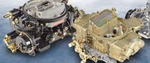
There are two most common types of fuel switches, which visually differ in practically nothing except the index. One is intended for a carburetor, the second for an injection power unit.
HBO button for injection engine
The button for switching the 2nd generation LPG to the injector has the index “W” and slightly modified wiring.
The LPG fuel type switch has 3 positions:
- Gasoline only (in this operating mode, the engine runs exclusively on gasoline, the indicator light does not light up or glows red);
- Gas only (this emergency mode is designed to start the engine on gas without pre-warming on gasoline, the indicator lights will flash in this operating mode)
- Automatic (when this operating mode is selected, the car starts in normal mode on gasoline, and when a given number of revolutions is reached, it switches to gas. The display shows the level of gas in the cylinder).
Setting up the 2nd generation HBO button for the injector
The functionality of the switch for an injection internal combustion engine includes:
- indication,
- Built-in emulator with time delay,
- The ability to regulate the number of revolutions at which the engine automatically switches from gasoline to gas.
For automatic operation of the car, you must correctly configure the LPG button, in particular, set the required number of revolutions at which the engine operating mode will change.
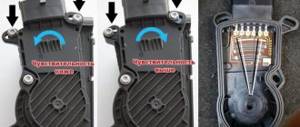
The adjustment occurs by rotating the potentiometer clockwise or counterclockwise, which is located directly on the device itself. The optimal speed is considered to be from 1500 to 2500.
Depending on the time of year and weather conditions, the number of revolutions can be changed:
- set lower speeds for the summer period
- higher for winter, so that switching to gas does not occur when the engine is not warmed up.
The button is supplied with:
- A set of wires for connecting to HBO.
- Plastic mounting bracket for attaching the device to a car dashboard or other convenient place.
- Mounting terminals for connecting power supply devices (reducer valve, emulator, etc.).
- Fuse and power cord.
LPG carburetor button
The fuel type switch for a carburized car has the index “G” and three positions:
- I – operating mode on gasoline only. In this operating mode, the gasoline pump is activated, and all gas equipment is turned off;
- 0 – operating mode in which both power supply systems are disabled. Allows you to exhaust the contents of the carburetor float chamber before switching to gas. This operating mode is necessary to prevent the internal combustion engine from flooding with two types of fuel at the same time.
- II – gas only operating mode. The car starts and runs exclusively on gas; the fuel supply to the gasoline pump is not used. During the spring-summer period of the year, you can operate a car without gasoline at all.
The front panel of the device has LED indicators that indicate what fuel the car is currently running on.
On the side panel of the device there is a potentiometer that regulates the gas supply time. If the engine for some reason does not work or does not start during this period of time, the gas supply is stopped automatically.
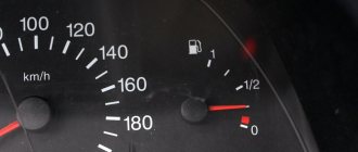
Most gas-gasoline switch buttons are additionally equipped with an indication of the amount of gas remaining in the cylinder.
HBO button connection diagram
Let's look at the connection diagram for the 2nd generation HBO button for an injection-driven internal combustion engine using the example of a product from the manufacturer stag2 and Digitronic.
It should be noted right away that the basic functionality and connection method itself are the same for almost all manufacturers. The recommended connection diagram must necessarily be included with the HBO switch. The connection diagram for the 2nd generation HBO button to the carburetor will have a similar appearance.
The wire set for stag2 and Digitronic products has the following colors:
- White. It is connected to the gas level sensor in the cylinder and is responsible for the correct indication on the fuel level button in the cylinder.
- Cyan (blue). It is connected to the electromagnetic gas valve, which is located on the reducer. When the device is switched to the “Gas” operating mode, the gas valve opens and gas is supplied to the reducer. An additional gas valve with a filter and an injector emulator can be connected in parallel to the same wire.
- Yellow. Connects to the solenoid valve in front of the gasoline pump. When the button is in the “gasoline” position, power is supplied to the gasoline solenoid valve and the car runs on its native fuel. When the car switches to the “gas” operating mode, no power is supplied and the fuel pump does not work. Many installers of gas equipment do not recommend turning off the gas pump, but insist that it works even when the vehicle is running on gas.
- Red. Power supply for the HBO button. You can connect directly to the positive terminal of the battery through the fuse and boot for it included in the kit. In this case, the HBO switch will be under constant voltage. If you want to power the gas-gasoline switch only when the ignition is turned on, you should take 12 volts from another place (for example, power supply to gasoline injectors).
- Black. Ground, needs to be connected to the car body.
- Brown. Connects to the control contact on the ignition coil. From here, information about the number of engine revolutions is taken and, accordingly, gas-gasoline operation is automatically switched. In the case of a carburetor engine, a signal is taken from here whether the engine is running or not; if the engine is turned off, no fuel is supplied.
gbo4auto.ru
Features of HBO 2 – carburetor and injector
Gas equipment of the 2nd generation on a carburetor is considered ideal, since it is on such engines that “wet” intake manifolds are installed. They have a small volume, which reduces the likelihood of ignition before entering the cylinders. Gas under pressure flows from the cylinder through a multivalve to a shut-off valve, where it is purified using a filter. It enters a heated gearbox, where it evaporates and enters the carburetor in a gaseous state through a power register that regulates the flow.
The gasoline supply is shut off by a solenoid valve in the fuel line. To prevent failure of the fuel pump, the valve must be mounted behind it, since the pump is lubricated with gasoline. Switching to another fuel is carried out by an electric switch, which is de-energized when the ignition is turned off. Cold start is only permissible on gasoline.
Before switching to gas, you need to let the engine run out of gasoline from the float chamber. To do this, the switch is switched to the “Transition” mode. When the thrust begins to fall, the “Gas” mode is set. Before long-term parking, the switch must be set to the “Gasoline” position. This will make the next launch easier.
HBO 2 fits perfectly on the injector, although here the supply is carried out through nozzles. There are no gas engines on this generation, so gas is supplied in front of the throttle valve. The intake manifold here has a large volume due to the air receiver, so there is a risk of ignition. To protect the flow meter and air filter housing from backfire, a special anti-pop valve is used.
On injection internal combustion engines, the supply is controlled by the ECU, which means that the gasoline-gas transition can be realized using electronics. A simple relay is used if there is no self-diagnosis system. If there is, Engine check will be triggered. To prevent this, an injector emulator is used that performs two functions:
- Disabling petrol injectors.
- Simulation of ECU operation.
It uses a lambda probe emulator that controls the mixture composition through the BC. On gas, the oxygen sensor will try to regulate the flow, but will not be able to, since it depends on the settings of the gearbox. The “Check” will light up again if the emulator does not send its signal to the ECU, which simulates the operation of a standard lambda probe.
The mode switch has the following positions:
- Petrol.
- Gas.
- Machine.
In the latter case, switching occurs without driver intervention. Cold starting is also difficult here.
HBO button 1-4 generations: connection to carburetor and injection cars
13.09.2018
To control the fuel system of a car with gas equipment, a gas-gasoline switch is installed in its interior. Models of LPG buttons vary depending on the generation of equipment and the type of engine of the machine.
Types of switches
Fuel switches for gas installations can be divided into 4 types:
- A key intended only for carburetor engines. Included in the 1-2 generation HBO set, has an index - G;
- toggle switch for an injection machine with the 2nd and 3rd generation of gas equipment, marked with the index - W;
- universal 2nd generation HBO switch for injector and carburetor;
- switch button gas petrol 4th generation.
Operating principle and differences between buttons
The 1-2 generation button on the carburetor has two working positions and one neutral.
1st generation HBO button for carburetor
- I – the engine starts and runs only on gasoline (gas valve is closed, the red light is on).
- II – The internal combustion engine switches to gas, while the gasoline electric valve closes and the green lamp lights up.
- 0 (Neutral) – serves to burn gasoline from the carburetor float chamber.
Changing the fuel type should only occur through the neutral position. If you turn on the gas right away, two types of fuel will enter the combustion chambers and the engine will most likely stall.
Some copies have an indication of the fuel level in the cylinder, as well as an additional button for the pre-start supply of a portion of gas, which is needed to enrich the mixture when starting a warm engine on gas (for example, Lovato, Logo buttons for a vacuum reducer).
A key such as, for example, Stag 2-G already has a pre-start function built into it, with the ability to adjust by time.
In the injection version, instead of the middle position, there is an automatic mode (on some types, such as Stag 2-W, it can be extreme). In this position, the engine starts on gasoline, and when a certain engine speed is reached, the gas supply is automatically turned on.
Button for switching gas petrol 2nd generation to injector
The transition speed is regulated using a potentiometer on the side surface of the housing. This key can also come with a level indication.
The universal option involves installing a toggle switch on both the injector and the carburetor. The transition between modes is carried out using a jumper/jumper on the case (example SVG switch).
Universal switch
The 4th generation HBO button has an LED indication and 2 operating modes on/off. In the on position, the gas turns on automatically after the reducer-evaporator warms up to 35-45˚C. The temperature is programmed in the controller when setting up the equipment.
Button signals using Stag as an example:
- LED is on/off – the engine is running on gas/gasoline;
- blinks at intervals of 1 second. – the engine is not warmed up;
- flashes every 2 seconds – the system is ready to switch to gas;
- blinks every 4 seconds – the tank has run out of fuel;
- the buzzer beeps three times - the system switches from gas to gasoline due to lack of fuel;
- three short signals 1 long – ECU (control unit) error;
- two short beeps 1 long beep (with the ignition off) – maintenance of gas equipment is required.
In addition, the fourth version of the gas system has an emergency start on gas. The mode is activated as follows: hold the button with the ignition off until the LED lights up continuously. Then, without releasing the key, we start the engine. Deactivation occurs after stopping the internal combustion engine.
Types of buttons (video):
Selection table (with approximate prices):
Name/marking injector/carburetor/generation Level indication, +/- Price in rubles
| REG OMVL Dream XXI King | engineer/4 | + | 1020 |
| Logo 145 | engineer/4 | — | 280 |
| Logo 101 | carb./1.2 | — | 470 |
| Atiker (K01.003.000.020) | carb./1.2 | + | 600 |
| Stag 2-G | carb./1.2 | — | 550 |
| AEB 722 | carb./1.2 | + | 1050 |
| Tamona K-5 | carb./1.2 | — | 520 |
| Lovato | carb./1.2 | — | 590 |
| Torelli | carb./1.2 | + | 630 |
| Stag 2-W | engineer/2 | — | 600 |
| Tamona in-3 | engineer/2 | — | 540 |
| Stag LED-401 | engineer/4 | + | 750 |
| Stag LED-300 | engineer/4 | + | 580 |
Connection diagram of the 2nd generation HBO button to the injector
Installing and connecting the 2nd generation HBO button with your own hands on a car with an injector sometimes causes difficulty.
In fact, everything is much simpler than it seems. The factory instructions for installing the switch indicate the following pinout:
- the white wire should go to the level sensor on the multivalve (if such an indicator is installed);
- yellow goes to the positive of the gasoline valve (if there is emulation of gasoline injectors, this wire is not connected);
- blue connects to the positive terminals of the gas valves of the reducer and the additional remote valve with filter. The injector emulator also cuts into this circuit;
- red goes to the positive terminal of the ignition coil (necessarily with a fuse);
- black - mass;
- brown to the negative terminal of the coil.
It’s hard to disagree with the first three points. But for the rest we will make recommendations:
- The red wire is best connected to the positive side of the ignition switch. Because the coils may have voltage surges. In order not to disassemble the panel, the contact can be found on the fuse block.
- The black wire should only be attached to the car body, like all negative equipment cables.
- Brown, must be wound onto the central high voltage wire of the coil.
It is advisable to do 10-15 turns, without using electrical tape. The electrical tape dries out over time and falls off; it is better to make a knot similar to tying a fish hook.
Correct connection of the brown wire
If the ignition system consists of separate coils, it is necessary to wind the wire onto the first two armor wires (for a more accurate signal), without breaking the brown one, i.e. first to the first then to the second.
After connecting the button, it must be adjusted. Periodically increasing the engine speed with the accelerator, it is necessary to smoothly turn the potentiometer screw clockwise and back. It is necessary to ensure that the gas supply is turned on in the “automatic” mode when the tachometer reading is 2000-2500 rpm.
Connection diagram of the 2nd generation HBO button to the carburetor
For a carburetor engine, the connection looks similar:
- Red - through the fuse to the ignition coil/switch.
- Light blue (blue) – gas valve positive.
- Yellow – positive of the gasoline valve.
- Black – minus (car body).
- The brown one goes to the ignition coil armored wire. It is needed to transmit an impulse to the key, which determines whether the motor is running or not.
If you still have questions about connecting or selecting buttons on the HBO, ask them in the comments. We will be happy to answer them.
LPG button 1-4 generations: connection to carburetor and injection cars Link to main publication
gbomotor.ru
How HBO 2 works
Liquefied propane-butane passes through the multivalve along the flow line. As soon as the driver switches the button to gas fuel, the electric valve will open the way to the evaporator reducer. Gas fuel will be sent to the internal combustion engine through a dispenser and mixer.
The difference with the operating principle of LPG 1 is that the fuel selection button, which is equipped with electronics, starts the car on gas without additional actions on the part of the driver.
If the engine does not start for some time, the electronics will close the gas supply to the gearbox. LED indicators on the LPG fuel switching panel will signal this. In fact, the gas solenoid valve will be de-energized. To start the car the next time, switch gas fuel to gasoline, or turn off the ignition and turn it on again.
The fuel type switch remote control allows the car to switch to gas from petrol automatically by pressing a button when it reaches a certain number of revolutions. This rule applies when installing 2nd generation LPG on an injector.
In the second generation of gas equipment, the buttons responsible for switching from gasoline to gas differ for injection and carburetor systems. When operating a car on gas fuel, the switch button is used to control engine operation. The operation of equipment using a gas mixture is based on the supply of pulses created by the ignition system.
The period of time when the gas valve opens when starting the engine, or until the required speed is reached at which the switch to gas occurs, is set on the fuel switching panel.
At temperatures below 10 degrees Celsius, before the engine starts running on gas fuel, you should warm up the engine on gasoline in normal mode.
Installing 2nd generation HBO on a carburetor
For installation on a carburetor car, it is most advisable to install 2nd generation LPG. It is best to choose components for installation from more or less well-known manufacturers such as BRC, Lovato, tomasetto. Although it is quite possible that their “Turkish copies” Atiker and others will also work quite adequately. Here it all depends on how much money, who and where will install and configure your gas equipment (some installers do not “like” messing around with installing and configuring “exotic things” such as gas reducers, etc., but this remains on their conscience). In previous articles, the 2nd generation LPG equipment and its detailed review were discussed; in this article we will consider the topic of installing a 2nd generation LPG on a carburetor.
Cylinder selection
The first thing you will need to decide is the type and placement of the gas cylinder for your car. For example, for classic VAZ or Moskvich models in a 4-door version, it is better to use a “cigar” type cylinder, which is located behind the rear seats in the trunk.
For the front-wheel drive VAZ family of three or five door modifications, the optimal choice would be to use a “Thor” type cylinder instead of a spare wheel (which will allow you to easily use the entire trunk volume with the rear seat folded).
For “Tavriy” and “Slavuta” it is best and most optimal to use a small “cigar” type cylinder located outside the car, which will allow you to “save” the useful volume of the trunk and allow you to use all the advantages of LPG.
Cylinder equipment
After choosing the type, size, and manufacturer of the cylinder, we look at what is included in the cylinder package
Thor
For a cylinder of the “Thor” type there must be:
- ventilation pipe (breather), which is led under the car;
- a cover with a seal to create a sealed chamber, which in emergency situations will not allow gas to flow into the cabin, but will allow it to escape through the ventilation tube outside the vehicle;
- clamps;
- fastening bolts with nuts and washers;
- original cover bolts that can be quickly unscrewed without tools and manually close the shut-off valve on the multivalve;
- passport for the cylinder.
Cylindrical cylinder (“Cigar”)
For a “cigar” there should be:
- ventilation box with gasket and lid;
- fastening tapes;
- two ventilation tubes (breathers);
- corrugation connecting the ventilation box with ventilation pipes;
- clamps for tightening corrugations;
- tapes for securing the cylinder;
- passport for the cylinder.
It is IMPORTANT that the lid itself and the seal of the lid of the torus cylinder are intact, just like in the ventilation box of a cigar, the sealing rubber must be intact exactly like the body and lid of the box. All ventilation hoses must be undamaged and clamped with clamps.
Multivalve
Installing 2nd generation gas equipment involves selecting and installing a multi-valve. After selecting a cylinder, select the appropriate multivalve for it. Based on experience, it is best to use a class “A” multivalve with an electric coil, which can be used to shut off the supply of liquid propane-butane to the flow line.
Multivalves from Lovato and Tomasseto have performed well in operation. The multivalve must have an O-ring and screws to secure it to the cylinder. Before installing the multivalve into the cylinder, it is necessary to check the ease of movement of the float and the operation of the shut-off valves. When installing, it is advisable to lubricate the rubber O-ring of the multivalve with a thin layer of silicone grease.
The multivalve can be supplied with or without a filling device. The filling device is selected based on the customer’s wishes and the technical feasibility of installation. Refueling devices are mounted either in the refueling hatch near the neck of the gas tank (for refueling you will need to have an extension cord with you). Or you can mount the refueling device in the bumper or under it, based on the installation capabilities of a specific car model.
The filling device and the cylinder are connected to each other by a line with a diameter of 8 mm to speed up the filling process.
Gearbox
Installing a 2nd generation gas equipment the next step involves installing a gearbox. The choice of a gas evaporator reducer consists of selecting a reducer based on power for a specific car model (with a small reserve of reducer power). For example, for classic and standard carburetor front-wheel drive VAZs, a Tomasetto AT 07 gas reducer with a power of 100 hp is sufficient, which already has a built-in filter for cleaning the liquid fraction of propane-butane and an electric valve for supplying/cutting off gas to the car engine.
If the selected evaporator reducer does not have a propane-butane liquid fraction filter, it is necessary to additionally install a coarse filter in front of the reducer, it is best if the design is assembled with a gas solenoid valve.
After selecting the reducer, evaporator and filter (if necessary) are mounted on the car. When installing the evaporator gearbox, attention should be paid to the correct installation in order to subsequently avoid the negative impact of acceleration/braking on the operation of the vehicle.
For example, according to the technical requirements of the manufacturer Tomasetto, the evaporator gearbox must be located along the axis of movement of the vehicle in order to eliminate the influence of membrane inertia during acceleration/braking.
Also, when installing the gearbox, you should take into account its height position relative to the cooling circuit; the gearbox should not be the highest point, otherwise it will be susceptible to the formation of vapor locks.
The coolant supply should also be provided with an antifreeze hose with an internal diameter no smaller than the outer fittings on the evaporator reducer. It is advisable to power the evaporator reducer parallel to the “stove” by inserting the appropriate tees. These measures will ensure a reliable supply of the required amount of heat to evaporate the propane-butane mixture during the cold season.
It is advisable to use antifreeze sleeves without strong bends, lay the bends of the sleeve in “springs”, and choose a material that is reinforced with inserts and is resistant to weathering and aging.
Connection and trunk
After installation, the reducer is connected to the gas supply line passing under the car body. The choice of material for the supply line is at the discretion of the customer, but mainly behind a thermoplastic tube (usually a 6 mm line is used for a carburetor passenger car).
The main line is laid away from hot parts and parts subject to constant movement. For installation, staples with self-tapping screws and plastic disposable ties are used (the staples and screws should preferably be galvanized, or better yet, stainless, and the ties are weather-resistant and ozone-resistant).
Mixer type
Next, determine the type of mixer that will be used for the car:
- The upper “turtle” mixer does not require modification of the carburetor. Placed between the carburetor and air filter. Sometimes it requires modifications to the air cleaner housing during installation;
- spacer in the carburetor (installed mainly in the “Ozone” type carburetor);
- inserts into the carburetor (very often used as an effective and simple method of mixing). Care is required when drilling holes and tapping threads in the carburetor.
Gas hoses from a reducer with an adjusting screw go to the mixer inlet if the mixer supplies both chambers simultaneously. Or the hoses come from a splitter (tee), at the ends of which there are “greed” screws.
“Greed” screws are screws that regulate the amount of propane-butane mixture when supplied to the car engine.
A large diameter gas hose goes from the reducer to the tee, and thin ones from the tee to the mixer. During installation, you need to ensure the shortest distance from the mixer to the tee (small hoses) by adjusting the required installation distance with the length of the large gas hose.
We cut into the gasoline solenoid valve by cutting the gas line as close to the carburetor as possible.
We connect the gas button and be sure to solder and carefully insulate all electrical connections.
This concludes our article on installing 2nd generation LPG on a carburetor. We have tried to describe in as much detail as possible the process of selecting and installing all the necessary components so that you have a complete understanding of the installation process.
gbo4auto.ru
Advantages and disadvantages of HBO 2
Despite some imperfections, 2nd generation gas equipment has its advantages:
- suitable for engines with fuel injection and for cars with carburetors;
- the design of second-generation gas equipment is simple and reliable;
- easy connection diagram and installation of gas equipment;
- it is easy to configure and regulate the system;
- An important advantage is that you can regularly start the engine on gas at an ambient temperature above 10 degrees Celsius.
The advantages of second-generation gas equipment include the low cost of repair kits.
- There is no feedback from the car engine, which leads to unstable operation in some modes (motor elements fail prematurely due to incorrect settings for the mixture quality or ignition timing).
- Increased gas consumption.
- There is a danger of a backfire of the gas mixture in the intake manifold.
- The emission of spent fuel in 2nd generation gas equipment does not comply with Euro-3 standards and higher.
- Slow response to pressing the accelerator pedal.
- The need to constantly adjust the valve clearance to prevent uneven engine operation under heavy loads.
When operating HBO 2, it should be borne in mind that water entering the air intake affects the number of revolutions.
On a note! The main modification of the power plant for gas equipment is to increase the compression ratio and integrate an octane corrector into the system.
You can’t do business with the 2nd generation of gas equipment today, since new versions of gas equipment have been released, which take into account many of the shortcomings.
HBO 2nd generation, equipment, principle of operation, pros and cons.
The development of gasoline fuel systems for engines led to the fact that HBO 1, which was perfectly suitable and worked on carburetor engines, was difficult to use for engines with fuel injection. This led to the emergence of 2nd generation HBO.
Description and equipment
HBO 2 was intended for converting both carburetor and fuel injection engines (mono injectors and other injection engines) to gas fuel. It should be noted that according to the European classification of generations, our HBO 2 is also the first generation among Europeans.
Unlike the first generation, the HBO 2 kit includes an electronic evaporator gearbox instead of a vacuum one, and instead of the usual fuel type switch button, there is a fuel selection button equipped with electronics.
Carburetor
The 2nd generation HBO kit for the carburetor now looks like this.
- Gas cylinder;
- filling valve;
- multivalve;
- filling and supply line;
- coarse filter (often built into the evaporator reducer);
- reducer-evaporator (electronic);
- button for switching fuel type "Gas" - "Petrol" with wiring. Accordingly, each type of engine (carburetor or injector) has its own button;
- mechanical dispenser (with one or two “greed” screws to adjust the amount of propane-butane mixture supplied to the car engine);
- mixer (for mixing propane-butane mixture with air);
- gasoline electric valve (which shuts off the supply of gasoline to the carburetor when the engine is running on gas).
Injector
HBO 2 on the injector has a set of equipment similar to the carburetor, with the exception of a few changes. In the configuration for the injection engine in the above list, instead of a gasoline electric valve, an injector operation emulator and a lambda probe emulator are used.
When the engine is running on gas, the injector emulator informs the gasoline controller about the supposed operation of gasoline injectors. This helps to avoid check engine error messages.
In addition to 2nd generation HBO emulators, a so-called “cracker” is installed on the injector. This is an anti-pop valve that prevents destruction of the intake manifold. Unlike aluminum carburetor versions, it is often made of plastic. The valve opens when there is excessive pressure in the intake manifold, and after the pressure normalizes, it closes again. It is mainly mounted on the air filter housing.
Principle of operation
The operating principle of the 2nd generation HBO is not fundamentally different from the operating principle of the 1st generation.
- The liquefied propane-butane mixture, located in a cylinder under pressure, is supplied through a multivalve and a flow line to the gas electric valve.
- Then, when the fuel selection button is switched to the gas position, the gas electrovalve opens the supply of the liquefied gas mixture to the evaporator reducer, and then, through the dispenser and mixer, to the engine.
The difference from HBO 1 is manifested only in the fact that the use of a fuel type selection button, equipped with electronics, allows you to start a car on gas fuel without additional manipulations. If the engine does not start within a certain period of time, the electronics of the button will automatically shut off the gas supply to the evaporator reducer, signaling this with LED indicators. At the physical level, this means de-energizing the electric gas valve.
For subsequent starting, you will need to either switch the fuel type to gasoline using the button, or turn off and turn on the ignition.
Therefore, in HBO 2 buttons, fuel type selection switches for carburetor and injection engines are different. (For example, the LPG button 2 from Stag for the carburetor will be Stag2-G, and for the injector Stag2-W).
Scheme of operation of HBO 2nd generation
In the future, when the car is running on gas, the fuel type switch button controls the operation of the engine. Operation on gas is based on pulses created by the ignition system, and in their absence (no pulses means no spark, the engine does not work), the voltage is removed from the electric gas valve. After the voltage is removed, the shut-off element shuts off the supply of the propane-butane mixture. And the indicators on the body of the fuel type switch button signal by glowing LED indicators that the operation has stopped.
The time for which the gas valve will be open when starting the car, and/or the speed at which the engine will automatically switch to operating on gas fuel is set on the fuel type switching button using a variable resistor.
In the cold season, before switching to operating the engine on gas fuel (at ambient temperatures below +10°C), the engine is first started and warmed up on gasoline in normal operation until the coolant temperature reaches about +40°C.
Advantages and disadvantages
The advantages of 2nd generation HBO include:
- Can be used in both fuel injection and carburetor engines.
- The simplicity of the design has been preserved.
- Easy to install and assemble.
- Easy to adjust.
- Possibility of regular engine start on a gas mixture at positive temperatures.
But there are also disadvantages that were inherent in 1st generation HBO:
- The main one is the lack of feedback from the engine. This leads to inefficient operation of the vehicle in some of its operating modes. And also to premature failure of engine elements, with incorrect adjustments of the mixture quality or ignition timing.
- Increased fuel consumption.
- Preserving the possibility of gas backfires in the intake manifold.
- It is not possible to ensure emissions in accordance with Euro-3 and higher standards.
- Delayed reaction to pressing the accelerator pedal.
All these factors gave impetus to the emergence of a new generation - HBO 3.
Do-it-yourself installation of HBO 2
The second generation gas cylinder equipment system is quite easy to install if you understand the basic principles of its operation.
The step-by-step installation guide for 2nd generation HBO includes the following steps:
Installation of gas cylinder and multivalve
This process is the same for both the first and fourth generations. The first thing you need to decide is what shape of cylinder you need, as well as the installation location. Step-by-step instructions for installing the cylinder on a classic, as well as in the trunk instead of a spare wheel, can be found here.
Installation of VZU
As in the previous paragraph, you should decide on the location of the remote refueling device. Usually it is mounted under the car bumper, because... this is the least labor-intensive option.
The very first installers did not bother with the placement of the VSU and mounted it directly in the trunk of the car next to the cylinder. It's even easier. But with this installation method, you will have to open the trunk to refill the cylinder.
In more expensive and modern cars, the VZU can be placed in the gas tank flap. In this case, the aesthetic appearance of the car will not be affected, but you will need to carry a special adapter for the gun with you. And when refueling, give it to the gas station employee.
Gas line laying
The next step is to lay a gas line from the LPG cylinder to the engine compartment. The installation is carried out under the bottom of the car, positioning the pipeline so as to minimize the risk of damage. Some installers advise placing the gas line next to the gasoline line. For safety reasons, we would still advise separating these highways.
Note! The outlet and inlet of the line are made slightly larger in diameter in order to be able to insert seals into them.
Read about what materials are used for highways here.
Mixer installation
The next step is to select a mixer that will be installed between the car's intake manifold and the carburetor. It is imperative to ensure a tight connection and prevent possible air leaks at the connection points.
Installation of solenoid valves
The next step is to install the gasoline and gas solenoid valve. Please note that there are several types of electromagnetic gas valves. The best option would be to choose a valve with a coarse filter.
Gearbox installation
Installing the gearbox is not a complicated procedure, but it must be done correctly, otherwise the entire system will work unstably. Read about how to properly install the gearbox on a classic in this article.
Connection and sealing
Next, all components of the system are connected and sealed well. At this stage, it is impossible to detect a leak, because There is no gas pressure in the system yet. After refueling (the first refueling should not exceed 5 liters of gas), you must carefully check all connections using a soap mixture. If a leak is detected, the connection must be sealed. If you can’t do this without disassembling it, you need to “repack” the connection.
Note! A more complete guide to installing 2nd generation HBO on a carburetor can be found here.
System adjustment
After you are convinced that all components of the system are sealed, you need to adjust and configure the 2nd generation LPG system. You can do this either independently or by contacting specialists, because in any case you will need documents from the system installers.
The adjustment process consists of several stages:
- it is necessary to adjust the sensitivity of the gearbox
- then adjust the gas mixture dispenser
- after that, when working on gas, adjust the idle speed of the car
- configure the gas-gasoline switch button by setting the conditions for switching to gas and back.
Read about how to configure the second generation HBO yourself in this article.
If you still have any questions, feel free to ask them in the comments to the article, and we will be happy to answer them.
gbo4auto.ru
Description and principle of operation
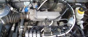
On carburetor engines, gas is supplied according to the same principle as gasoline, through the carburetor.
On injection engines, gasoline enters the engine through injectors and it is not possible to supply gas through the same injectors. But at the time when engines with point injection of gasoline were released, there was no gas equipment that replicated the operation of the injector. There was only one way out: supply gas in front of the throttle valve. Everything would be fine, but in essence such a conversion turns an injection engine into a carburetor one. As is known, large-volume intake manifolds with air reserve receivers are installed in injection engines. So, when operating on gas, these receivers are filled with a gas-air mixture, which can ignite. This fact imposed some peculiarities on the installation of 2nd generation gas equipment on the injector. In particular, we had to take care of protection against explosions in the intake manifold (backfire). An anti-pop valve must be installed in front of the gas mixer to protect the air flow meter (MAF) and the air filter housing with a corrugated duct from explosion. Basically, faucets with an integrated anti-cotton valve are used for these purposes, but there are also options with separate units.
Since the supply of gasoline is controlled by the control unit using electronics, it is possible to turn off gasoline when running on gas electronically. Even a conventional electromagnetic relay may be suitable for this, which will turn off the power supply to the gasoline injectors at the right time. If the car is not equipped with a self-diagnosis system, then the option with a relay will work flawlessly, but if the standard ECU has a component diagnostic system, the controller will see an open circuit of the gasoline injectors and go into emergency mode. At the same time, the “check engine” lamp on the display will light up. In different systems, emergency operation occurs in different ways; in some systems it occurs without any changes, and in some it goes as far as stopping the engine completely. To combat this problem, a device called “Injector Operation Emulator” is used. This device performs 2 functions:
- Disabling petrol injectors when running on gas
- Making it appear to the standard ECU that the gasoline injector is operating in its normal mode.
Important!!! Do not turn off the fuel pump when running on gas. This will lead to premature failure of the entire vehicle power system. The gasoline pump, fuel lines, gasoline injectors and pressure regulators must be flushed and cooled with gasoline. If this is not done, they will dry out and fail. There should always be gasoline in the gas tank!!! Warming up a cold engine should only be done using gasoline!!!
There is another device in the second generation of LPG on the injector, which is not on the carburetor, this is an emulator of the operation of a lambda probe. On injection engines it is possible to control the amount of fuel; this is done by the standard control unit. Using its factory tables and based on the readings of information sensors, the computer regulates the fuel supply to the engine. The lambda probe is one of the information sensors. It shows what condition the mixture is in, lean or rich. If the mixture is lean, the computer supplies more fuel; if it is rich, it cuts it off. But when working on second-generation gas equipment, the ECU does not have the ability to control the amount of gas. This may cause problems. The fact is that the normal operation of the engine is controlled by a constant shift of Lambda from a rich state to a lean one. This is impossible to achieve with a traditional gas pump, because the gas reducer always produces the same amount of gas specified during adjustment. At the same time, the lambda shows one state, and the ECU tries to change it. When the system sees that there is no reaction to a change in fuel supply, a message is displayed in the form of a burning CHECK lamp indicating that the Lambda probe sensor is faulty and the controller puts the car into emergency mode. The Lambda probe emulator, when running on gas, breaks the circuit between the ECU and the sensor and sends its readings to the controller. This signal changes from a poor state to a rich state and back. Perhaps these are all the features of the operating principle of the second generation of gas equipment on injection engines.
see also
- VAZ 2107 do-it-yourself generator repair
- Method of parking a vehicle
- What happens if you don’t surrender your license after deprivation on time?
- The check light comes on when driving
- Adjusting the carburetor ZIL 130
- How to turn on the side lights
- How to sign up for a driver’s license through government services
- How is car tax calculated?
- VAZ 2110 engine gets hot 16 valve injector reasons
- Passat SS 2019
- Gelendvagen Mercedes characteristics