When the ignition is turned on, the relay creates pressure in the fuel lines by turning on the fuel pump (BN) for a couple of seconds. After this, the BN will work either when the engine is cranked by the starter, or when the engine is running.
Sometimes this system needs repairs - there is nothing complicated here, and the editors of the 2Skhema.ru website will tell you how to do it yourself. Let's start with the BN pinout, then we will indicate it on the diagrams and at the end there will be instructions for replacing the fuel supply elements.
Pinout of fuel pump VAZ 2107
1 – radiator fan drive motor; 2 – mounting block block; 3 — idle speed sensor; 4 – engine ECU; 5 – potentiometer; 6 – set of spark plugs; 7 – ignition control unit; 8 – electronic crankshaft position sensor; 9 – electric fuel pump; 10 – indicator of the number of revolutions; 11 – lamp for monitoring the health of electronic systems and the brake system; 12 – ignition system control relay; 13 – speedometer sensor; 14 – special factory connector for reading errors using the BC; 15 – injector harness; 16 – adsorber solenoid valve; 17, 18, 19,20 – fuse box for repairing the mounting block that protects the injection system circuits; 21 – electronic fuel pump control relay; 22 – electronic relay for controlling the exhaust manifold heating system; 23 – exhaust manifold heating system; 24 – fuse protecting the heater circuit; 25 – electronic air sensor; 26 – coolant temperature control sensor; 27 – electronic air damper sensor; 28 – air temperature sensor; 29 – pressure control sensor and low oil pressure lamp.
You can check the fuel pump on a VAZ 2107 simply by checking the voltage at its connection block with a tester. The presence of voltage will indicate a malfunction of the electric motor. Instead of a tester (multimeter), you can use a test lamp to diagnose a malfunction.
In the absence of one, this can be done by disconnecting the connection block for the fuel pump and fuel level control and applying voltage with wires from the battery to the place where the gray wire is connected +12 and to the place where the black wire is connected - minus. A humming pump will indicate a faulty fuse, power circuit or ECU.
Repair and tuning VAZ
Today I returned from a friend. Initially he had a carburetor, then he decided to make an overhaul + tune the car a little. At my suggestion, he decided to build an injector. Fortunately, all the spare parts necessary for this turned up. parts. Today I told him how to connect it all. Well, naturally, he didn’t understand much, so I decided to write a fairly detailed guide about connecting. In fact, a lot of people have been asking about this lately. Hope this will be useful. There are different modifications of injectors, with and without an oxygen sensor, with and without an absorber, phased, pair-parallel and simultaneous injection. There are also different mounting blocks. For example, I took COURT January 5.1 (Bosch 1.5.4), i.e. without absorber and DC. On the electrical equipment side there is a high panel with a mounting block 2112-3722010-60.
First, the entire COURT diagram
Now let's see what needs to be changed in the engine compartment.
Let's start with the fan. This braid has a single contact; if you open the insulation a little, you can see that it comes with a black and white wire.
This is the contact for connecting the fan.
The fan worked differently on different units, but the main feature was that it was turned on by a sensor on the radiator. Now it will be turned on by the injector unit. And instead of the old scheme
It will be switched on according to a new scheme from the “brains”
Those. you just need to take and attach one contact to the body, and connect the second to the black and white wire from the braid. All with a fan!
Now about other contacts... Here's the overall picture
I will not look at all the sensor plugs, but will only look at those points that confuse a novice electrician. Two brown wires have appeared in the engine compartment
These are the “minuses” that are named G1 and G2 in the SUD diagram. They need to be screwed onto the body. Usually they are screwed onto the cylinder head in the area of the thermostat.
One black wire also appeared
In fact, this is an optical illusion. This is actually the red wire. You can verify this by moving the insulation back a little. This is “+12” which is attached directly to the battery. It feeds the "brains".
Well, that seems to be all. There was nothing else unknown in the engine compartment. Now let's see what's going on inside the car.
Let's look at the connections of the fuel pump.
In the carb version, two wires approached the tank
The fact is that in a carburetor circuit, the external fuel pump is located in the engine compartment, and these wires simply go to the gasoline level sensor. One, blue and red, supplies voltage, the second, pink, transmits information about the presence of gasoline. In this case (injector), we have a fuel pump in the tank. and it is connected using a block
In order not to pull unnecessary wires, you should do this: connect the old wires to the block as shown below
Now we have power supply connected to the fuel pump and a contact indicating the fuel level. We throw the black and white wire to minus. those. frame. The blue-red wire is not needed. Everything in the gas tank area is connected.
Now let's look at the connection in the instrument panel area. Previously, the old contacts (power supply for the level sensor and signal) were connected via a mounting block to the instrument panel
those. We do not touch contact 11 of the white block. This is the contact that shows the fuel level. But we disconnect pin 11 of the red block from the instrument panel. It needs to be connected to the contact that comes from the COURT harness
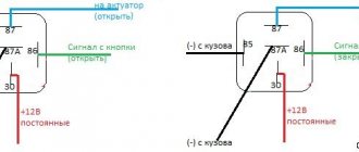
Next, we’ll think about how to connect the SUD wiring to the cabin wiring braid. The connection block looks like this
In the diagram it looks like this
Among these contacts there are: 1) red-blue (1 contact according to the diagram) wire is “+12” which is connected in the area of the ignition switch. It delivers +12 and turns on the brain when you turn the ignition key
2) gray (pin 2 according to the diagram) is a car speed signal.
3) white-purple (pin 6 according to the diagram) this is the signal of the Check light
4) red-purple (pin 8 according to the diagram) is a tachometer signal. Low voltage.
5) yellow-black (pin 3 according to the diagram) is fuel consumption.
As far as I understand, the fuel consumption signal and the speed signal are connected to the BC.
Check, you need to look for the tachometer according to the diagram... Unfortunately, I don’t know where they are connected on the standard panel. But you can try by brute force, excluding known contacts. Those. unknown only - in white - 1,2,3,6,7,10 in red - 1,5,6,9,11 in yellow - 1,4,5,6,8 known contacts can be found here
https://www.autoelectric.ru/auto/vaz/vdo/vdo2115.gif
In general, on the Internet I came across the designation of all the contacts of the panel... you have to look for it.
What else is interesting in the engine compartment...
Diagnostic block
Immobilizer block
contacts for the immo tablet and the immo warning light. (If you do not plan to install an immobilizer, then they do not need to be connected)
There are still unknown wires... I don’t know what they’re for... maybe the air conditioner, maybe the BC, maybe something else. Those. in theory they may be correctly conceived, but in practice they are not needed, since there is nothing to attach them to
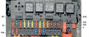
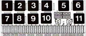
The strip itself with a relay (there are no relays in the photo) and fuses looks like this -
there are three circuits of relays and fuses: the main one, the fan, the fuel pump.
Well, that's basically all. I think the main points will be clear... And you can figure out the subtleties yourself
I would like to answer that I have not personally tested this in practice, so I could be wrong. Its own system, which runs on January 7.2. I implemented it.
Regarding this system January 5.1. I think we’ll check it out soon... for now this is just my theoretical justification. If anyone has any additions or can point out errors, please leave comments.
You can also discuss this article on the forum https://www.lada-samara.com
PS I also wanted to say - who knows why very often the color of the wires according to the diagram does not correspond to the color of the wires in real life. Don't know.
PPS a week after the publication of this article, it was tested in practice. everything is working.
Pinout BN VAZ 2108, 2109, 21099
The fuel pump activation relay (2) is shown by an arrow.
- Injection on a classic: wiring diagram for a VAZ 2107 injector to help the car owner
A - to terminal “B+” of the generator; B - block connected to block K of the ignition system harness; C - block connected to block L of the ignition system harness; D - wire connected to the interior lamp switch; E - wire connected to the white and black wires disconnected from the interior lamp switch; F - to the “+” terminal of the battery; G1, G2 - grounding points; K - block connected to block B of the front harness; L — block connected to block C of the front harness.
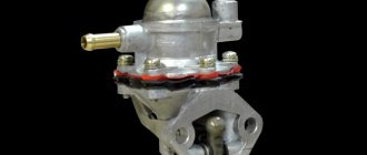
On “nines” with a mechanical fuel pump, the most common malfunction is wear of the fuel pump diaphragm, as a result of which gasoline will leak through the drainage hole in the housing when it operates. The second reason for the failure of such a fuel pump is wear of the pusher, which transmits force from the camshaft cam to the fuel pump drive lever.
Replacing an electric fuel pump on a VAZ
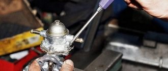
- Reduce pressure in the fuel supply system.
- Using the fuel supply hose tip clamp, disconnect 2 hoses in turn.
- Unscrew the 8 nuts around the circumference of the clamping ring and remove it.
- A wire with negative polarity is attached to one of the nuts; it must be removed carefully.
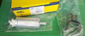
- We take the electric pump block out of the fuel tank, tilting it slightly, to keep the fuel level indicator sensor lever intact, otherwise it will produce incorrect parameters.
- Remove the sealing rubber ring of the fuel block. If its properties are lost, the product must be replaced.
- Install the pump in reverse order.
When installing fuel hoses, focus on the direction of fuel supply indicated by the arrows, and the installation arrow on the electric pump cover should point towards the rear of the car!
- Installation on VAZ 2108 and 2109 with a low torpedo instrument cluster from 2115
How to remove the fuel pump
The VAZ 2109 fuel pump is located under the rear seat. The injector implies its installation directly in the tank. The thing is that the pump is a submersible type. In the same unit there is a float-type fuel level sensor. It works due to the fact that the float moves the slider using variable resistance. At the same time, the current in the power circuit changes. The amount of gasoline remaining in the tank is determined by the magnitude of the change. To remove the pump you will need to use pliers, screwdrivers and an 8mm wrench.
It is quite possible that the reason that fuel is not supplied is a non-working VAZ 2109 fuel pump relay. The injector contains it, as well as a fuse, which could easily burn out. Before starting work, thoroughly clean the entire cover so that after removal no dust gets inside the tank. Then, using a screwdriver, loosen the clamps that secure the hoses. Remove them; if you can’t do it with your hands, try gently squeezing them with pliers and twisting them. After this, use a size 8 wrench to unscrew all the nuts that secure the lid to the tank body. Please note that there are washers there. Don't lose them. That's all, now the pump can be easily removed for replacement or repair.
Video instructions for replacement
—> VAZ Masters / Engine power system / Gasoline pump
- How to install an additional starter relay on a VAZ 2110? Assembly diagram
Electric fuel pump
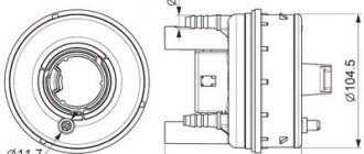
Purpose
Electric fuel pump VAZ 2110
The principle operation of an electric fuel pump is based on pushing fuel under pressure into the engine. Conventional VAZ fuel pumps suck gasoline from the gas tank; a small gap from the pump to the carburetor allows it to operate at low pressure. Electric fuel pumps of the first VAZ cars worked at the same speed. The industry has launched the production of pumps that meet the growing requirements of the automotive industry; now their operation is completely dependent on the speed of the engine.
Note. The vehicle's electronic system controls the operation of the fuel pump. It corresponds to several factors: ambient temperature, what position the throttle is in, and the composition of the exhaust gases.
Electric fuel pumps operate under pressure, resulting in increased noise and rapid heating. For these reasons, they are installed in the gas tank. Gasoline cools and muffles the sound of the running pump.
VAZ 2110 fuel pump connector number
Dear visitors of the “Cars” website! We will be very grateful for your comments on the video clip “VAZ 2110 fuel pump connector number”; registration is not required for this. We also ask you to let us know if you have any problems playing the video.
a question. and always after the engine is turned off. When the pressure gauge is connected, the pressure in the rail should be maintained. that is, the arrow should not fall even a little. and what does it mean if it falls?
07/25/2017 – 06:49 Oleg 1974
Good afternoon, I’ll ask you a question as I’ve already asked others, but I don’t know a specific answer. The question is that I have an injection branded pickup truck with an engine capacity of 1. 3, the same one is installed on a ZAZ Sens. I decided to measure the pressure on the fuel rail 1 turn of the key without starting the engine 2. 9 kgcm. after 15 seconds it drops sharply to 2.0kgcm. 2starting the engine 2. 3kgcm. I sharply give the speed 2.9 kgcm. 4 I compress the return line 6. 0kgcm. After stopping the engine, the pressure remains for several hours. The fuel pressure regulator changed the readings to the same as described above. The fuel pressure regulator from the factory is 2112, the same as on VAZs, only on VAZs for some reason the pressure is 3.0 kgcm. constantly and this is considered the norm, maybe it’s the volume of 1.5 and 1.3 engines that makes such a difference. Or maybe the old R.D.T. failed and the new one was defective. I really hope for a clear answer from a specialist.
07/02/2017 – 03:37 VLADISLAV OLEGOVICH
if your car service wants to shoot normal videos, then first get a normal camera
06.24.2017 – 18:45 dushaa
Good afternoon, 2110 without return, pressure 4, when running it jumps 3 to 4, gradually drops. Problem when changing gear from 3 to 4 choking. Is there a problem with the fuel pump? kkvv 0.92
Can't see anything in the car service, no portable lamp? black screen. you speak to the blind. failure.
06/03/2017 – 17:39 Joe Joker
When the ignition is turned on, the pump pumps and pumps 3 bar, only the pump stops and the pressure drops to 0. When the internal combustion engine is running, it shows 2.5-8 bar. When the hose is removed from the turbocharger, the fuel pressure regulator increases to 3 bar. I put it on and it drops to 2.5-8 bar. The engine runs for about 10 minutes, the check light comes on, the engine starts to titrate, the pressure in the ramp at idle increases to 2.9 sometimes up to 3 bar. When I turn off the engine, the pressure immediately drops to zero and as a result the engine does not pull and develops power poorly. but when you start it, it pulls and tears out from under itself, about 10 minutes pass, the check light comes on and it’s like they’re holding it by the ass, you turn it off and start it right away again it tears everything fine. car vaz 2110. tell me what is the reason?
05/11/2017 – 19:16 Dmitry Demidov
Hello. Everything is about the same for me, but the pressure is a little lower. And the needle is not like yours - it stands rooted to the spot, but shakes within 0.1 atm. Could you please comment? Here is the video of the measurement
05/06/2017 – 22:15 Sergey Vladimirovich
I have 2.2-2 with the engine running and idling. 3 atm. I remove the hose from the RTD and it rises to 3 atm. Put it back and it drops to 2.2 atm. mesh and filter are replaceable. At idle I pinch the return hose and it rises to 6.5 atm. Why doesn’t it even rise to 2.5 atm at idle? engine 8 cl 1.5 with return.
04/23/2017 – 08:04 VAZIK BASHIN
a friend tell me, I'm already tired of the car at the bottom, kickdown, you're pushing the engine into a choke, I changed everything until I got to the fuel system, I measured the pressure = with it turned off, 1.5 atmosf. When I start 2.5, when I accelerate, the hose drops a little, but the hose does not rise, I pull off any changes, should I change the pump in conjunction with the RTD?? 2115 8klp
Work process
Electric fuel pump for VAZ 2110
The driver turns on the ignition switch, a signal is sent from the on-board computer to the electric motor of the pump, in which an electric charge occurs. A motor starts working inside the pump itself, creating a working pressure level in the fuel supply system in a few seconds. After three seconds, the on-board computer does not give a signal to start the engine, and the pump motor automatically turns off. At this time, you can hear the operation of the electric fuel pump. In the first seconds of the pump starting to operate, gasoline enters it through the tube. The fuel exits through a special one-way valve installed by the manufacturer, which traps debris and impurities.
Reasons for failure and replacement
VAZ 2110 connecting an electric fuel pump
Fuel pump failure occurs for several reasons:
- driving with an empty gas tank;
- failure to replace the fuel filter on time and much more.
Due to non-compliance with such simple rules, the electric fuel pump wears out. Therefore, malfunctions in the fuel system occur prematurely.
Note: it is necessary to change fuel filters on time, especially when filling with low-quality gasoline. Follow the main rule: the gas tank should always be more than half full.
Preparation for repair
Before starting repairs and replacing the electric fuel pump, you must:
- disconnect the negative terminal on the battery;
- remove the cap from the gas tank to prevent the creation of rarefied vapors;
- check the fuel level, it should be at the middle level in the gas tank, but no more;
- You should also place a fire extinguisher nearby, just check its expiration date in advance.
To relieve pressure in the pipeline, you must start the engine and leave it running until it stops completely.
Note: work must be carried out using a lamp with a protective cap. You need to prepare clean rags and plastic containers in advance for the fuel pump to be removed, as there will be residual fuel in it.
After completing the preparatory work, recline the rear seat and remove the protective cap of the gas tank.
Replacement
VAZ 2110 electric fuel pump diagram
Carry out work carefully, legibly and consistently:
- disconnect the gas tank connector;
- loosen the clamp;
- unscrew the tubes using special wrenches;
- remove the rubber gaskets;
- unscrew the eight bolts on the body;
- remove the sealing ring;
- remove the fuel pump.
Note: replace the rubber gaskets on both pipeline fittings using a repair kit. The fuel pump must be placed on a pre-prepared rag or in a plastic container.
VAZ 2110 electric fuel pump and its removal
The pump is gradually pulled up and tilted towards the backs of the seats to avoid deformation of the float. Remaining gasoline may spill during this work. The last thing is to remove the rubber gasket. When replacing not the entire module, but only the fuel pump, you will have to spend time and effort:
- remove the locking spring from one guide;
- compress the fixation plates;
- disconnect the module;
- remove the fence mesh;
- disconnect the terminals from the pump and fuel level sensor;
- remove the polypropylene fuel pipe, it is connected securely, so you will need to act carefully, but with effort;
- remove and replace the pump.
Note: replacing the fuel pump must be done with replacing the fuel filter.
Assembly
VAZ 2110 fuel pump wiring diagram
The module must be assembled in the reverse order. The main thing to take into account is that the arrow of the mark is directed towards the rear of the car. Then both tubes are screwed on and the wire is connected. The protective cover is installed in its place.
VAZ 21102 electric fuel pump
Note: all repair work must be carried out in compliance with fire safety measures.
Replacing an electric fuel pump with your own hands is not difficult. You just need to carefully study the instructions and be patient and attentive. Before carrying out this work, you need to view the video and photographs. Photos can also be used during work. Place them in the required sequence. The price of a fuel pump, repair kit, fuel filter is within 2000 rubles. Carrying out work on replacing a fuel pump does not require great qualifications. Therefore, a motorist of any category can handle it. After completing the work, all rags must be collected and disposed of. Old cuffs and pads must also be disposed of.
Add a commentAdd a comment We advise you to readVAZ 2109: fuel pump malfunction - identify and fix itVAZ 2109: oil is leaking from the fuel pump - what to doVAZ 2110: fuel pump relay - operating principleReplacing the VAZ 2110 fuel pump filter on your own
So, an electric low-pressure fuel pump on fuel-injected cars is located in the gas tank and takes fuel from the fuel tank, after which it supplies it under a certain pressure to the injectors. As a result, the engine operates stably regardless of the load, and accurate and timely injection is also achieved.
Carburetor cars are equipped with a mechanical fuel pump as standard. This device is located under the hood next to the carburetor, driven by the engine, but it operates less stable and has worse performance compared to an electric pump. As a rule, a mechanical pump can fail due to problems with the membranes; the fuel pump also often overheats, etc.
In both the first and second cases, the pump supplies fuel to the metering systems (injectors or carburetor). It is quite obvious that if you install an electric pump instead of a mechanical pump, you can achieve trouble-free operation of the carburetor and a stable fuel supply.
However, it is important to understand that the electric fuel pump on the carburetor must operate at low pressure to avoid fuel overflow. As for the installation itself, in some cases the electric pump is installed under the hood, and not in the tank (as on an injector). Also quite common is the option when the pump section is integrated directly into the gas tank.
Installing an electric fuel pump on a carburetor
Let us immediately note that installing an electric fuel pump on a carburetor internal combustion engine is associated with a number of difficulties. Please note that without proper experience in carrying out such work, it is not recommended to carry out the specified modifications to the fuel system yourself.
Now let's look at a common installation method with an example. First of all, you need to select the most suitable electric fuel pump in terms of performance for the specific type of internal combustion engine and the carburetor installed on the car.
In addition to the pump, you should also prepare the following items:
- hose 5 meters long, internal diameter of the hose is about 8-9 mm;
- an additional relay will be required;
- you also need to have a 3 or 4 mm drill;
- you will also need a fuel filter from injection systems;
- fuel filter for carburetor systems;
- steel tube 7 mm with a wall of 0.8 mm and a length of 25 cm;
- fuel hose with an internal diameter of 12 mm;
- adapter fitting from 8 mm to 12 mm;
Having prepared everything you need, you can proceed to installation. First you will need to remove the fuel level sensor in the gas tank. Then a hole is drilled in the sensor cover, then a 7 mm tube is soldered into the hole with a soldering iron. It is important to bend the tip of the tube so as to drain the return as far as possible from the fuel intake.
Also, the upper end of the tube is bent parallel to the outlet of the fuel intake. Now a modified fuel level sensor with an intake and return should be installed in the tank. It should be taken into account that the rubber tube will need to be connected to the installed return fitting from the standard fuel line.
Now one end of a hose with a length of 5 meters is put on the fuel intake fitting. After the rubber fuel supply hose has been connected, the said hose is securely attached to the metal tube. This can be done by using clamps.
Next we move on to installing the electric fuel pump. The device should be mounted on the engine shield, positioned horizontally. The installation takes place on a bracket; special rubber pads are also installed, which are sold together with the pump or purchased separately.
When installing, it is important to ensure that the pump is positioned correctly (fuel is sucked in from the side of the expansion tank, and the supply goes to the engine). Next, a fuel filter from the injection systems is installed on the rubber supply hose. A hose 5 cm long should be put on the second fitting. This hose is subsequently secured with clamps to the car body in a vertical position.
This is necessary so that fuel is supplied from bottom to top. The electric fuel pump itself is connected to the gas tank using a 12mm hose. A steel adapter is used for connection. At this stage, the pump connection can be considered complete. Now we need to deal with the issue of pressure of the new pump, which is higher than that of a mechanical one. If the pressure is high, the carburetor will flood.
To solve the problem, modifications will be required. First of all, the top cover is removed from the pump, the supply fitting is unscrewed, and then the mesh is removed. Next, the hole is drilled 1-3 mm with a pre-prepared drill. Now all that remains is to complete the final assembly, connect the fuel pump through a hose, installing a fuel filter for carburetor systems in parallel. For this, a rubber tube is used, fixation is achieved using clamps.
As for the power supply to the pump, the device is connected via a power relay to the 12 V contact, which is located on the ignition coil.
Where is the fuel pump located and how to get to it
Let’s begin to figure it out step by step to find out in detail the location of this important part:
- We move the front seats forward to have more space.
- On the back sofa we see a small rope, we take hold of it, moving the back seat, under it we see the gas tank hatch, lift it and find the gas pump.
- Next, we look for the fan relay. We find it under the glove compartment on the front side.
- Where is the starter relay located? The relay controls the starter, which can cause malfunctions: when you turn the ignition key, the engine does not start; There is a clicking sound when starting the engine. This relay is located under the hood, behind the air pipe.
- It's the turn of the temperature sensor. It is located under the hood, next to the wiring that is located between the rear of the engine.
- Where is the speed sensor in the VAZ 21099? It is located under the hood. To get to it you need to unscrew two bolts. We take them out and see the sensor near the gearbox, connect the wires to it, which we must disconnect.
- Fuel filter locations. Its purpose is to clean gasoline from debris. Also, characteristic jerks appear when it becomes clogged. It is located at the bottom of the body, near the gas tank.
In general, if the car does not start, then you need to check the fuel pump. We hear characteristic sounds from the pump under the rear seat. If it does not work, it is worth checking its integrity, as well as the fuel pump relay.
After all the operations performed, having figured out the problem of the breakdown, we can repair the car ourselves or at least determine the cause of the malfunction. Since, having already studied the entire car system in more detail, we can say that everything doesn’t look as complicated as it actually is.
Advantages and disadvantages of installing an electric fuel pump on a carburetor engine
In the list of main advantages after installing an electric pump on a carburetor, we should highlight the ease of starting the internal combustion engine. The engine starts quickly, both cold and hot, reducing the load on the battery and starter. As for operation, if connected correctly, there is not so much smell of gasoline in the cabin, and fuel is also consumed more economically.
We also recommend reading the article about why the fuel pump starts to hum. From this article you will learn why the fuel pump hummed, as well as what the driver should do to fix the problem.
If we talk about the disadvantages, then it is worth noting only the complexity of installation and the need to purchase the pump itself. Also, for normal operation of the pump, the vehicle’s electrical systems must be in good working order, as well as a normal battery charge level.