- the number of organizations providing trailer rental services is increasing;
- Traveling with campers (caravan trailers) is becoming popular;
- the number of owners of hydro- and ATVs is growing;
- Carriages are widely used for transporting vehicles.
Also, many motorists install towbars and universal electrical connectors (sockets) “just in case,” assuming that in the future they may use trailers.
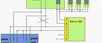
Let's look at the connection diagram for the towbar socket and how the pinout of the towbar socket is done, so that later you can connect any device on a rigid hitch without any problems.
Types, pinouts and connection diagrams for towbar sockets
Several types of connectors are used to connect trailers:
- seven-pin (7 pin) European-type connectors;
- American-type seven-pin (7 pin) connectors;
- thirteen-pin connectors (13 pin);
- special connectors.
The most widely used 7-pin European style connector is found on most passenger car cargo trailers. Its diagram and appearance are shown in the figure:
A special feature of the connector is that the receiving part and its mating parts have sockets of both types (“male” and “female”). This is done for reasons of safe connection of the circular connector in zero visibility conditions.
It is almost impossible to install incorrectly or short-circuit the sockets with this arrangement. Each of the connector pins has a clear purpose. The table shows the areas of the minimum cross-section of wires that are used to connect to the required circuit element.
Contact No. 2 may not be used on many trailers. It is used to provide constant +12 power supply to light duty trailers. Some car enthusiasts ignore the separation of the right and left side lights, combining them circuit-wise into a single wire.
A slight “simplification” of the electrical wiring leads to a disruption of the “parking light” function (when the turn signal is turned on in the parking lot, the dimensions of the corresponding side light up). This function is used when parking on the side of the road.
Pinout diagram for 7-pin American connector:
A special feature of the connector is the presence of a reverse contact and the absence of separation between the right and left rows of side lights. In some models of American cars, there is no separation between side lights and brake lights (they run on one wire).
In many cases, the set of towbar connectors already includes conductors of the appropriate color and cross-section. This greatly simplifies the electrical connection process.
13-pin connectors are used to connect passenger trailers.
The main difference between this connector is that there are several contacts for the negative and positive buses, and backup contacts for connecting additional devices (for example, a rear view camera).
A special feature of the connector is that large currents can flow through its contacts, in particular, to power the household electrical equipment of a caravan trailer and charge an additional battery.
Special connectors are sometimes used to connect to boat equipment. In this case, standard adapters are provided.
Modern trailers of a higher class have their own electronic equipment: ABS, ESP systems, on-board computers. They are also connected to the vehicle’s on-board system using special connectors.
Types of connectors and connection methods
The method of connecting a car towbar to the electrical wiring is determined by the type of block installed on the towbar. One of several types of connectors can be used for connection.
There are the following types:
- 13 pin output. This type is used in the Russian Federation and neighboring countries more often than others. Such connectors are equipped with additional positive and negative wires, which allows you to connect not only rear lights, but also the network in motor homes.
- 7-pin connector. American models have a similar device, but differ in wiring.
- Special pads (special) are installed on certain brands of cars.
- 15-pin outputs, which are used on tractors.
Standard method
Features of connection in a standard way:
- It is more relevant for older cars that do not use an electronic control module and coordination of engine operation. Therefore, the contacts must be connected to the general network using standard wiring.
- The car owner will not have to use branching devices to perform this task.
- It is necessary to connect the towbar to the trailer so that the optical devices on the latter work correctly.
- If the car is equipped with an anti-theft device, then an additional connection to the limit switch must be made.
- The device must be connected so that the trailer's optical devices work synchronized with the car's rear lights. To do this, the contacts must be connected to the optics. To achieve this, appropriate connectors are used.
After connecting, there may be an extra wire left; you will need to use it to connect the second turning light to the trailer.
This problem can be solved in two ways:
- Using a volumetric clip.
- By stripping the cable from the insulating sheath. It is then connected to the conductor that comes from the outlet of the outlet. The connection is made by soldering.
The “Monstrokhod” channel talked about how to make wiring to connect an electrical outlet in a car.
Universal method
In modern cars, connecting the contact component of the trailer to the vehicle's electrical network is carried out using a universal method. Such vehicles are characterized by a more complex on-board system, so they require the connection of a matching module. The latter plays an important role during installation and is used to constantly check the operation of the rear optics.
Option 1
You need to establish a connection like this:
- Before performing the task, you should make sure that you have wires with the required, but not excessive cross-section. If required, cables are made independently. For this, conductors with 2 or 3 cores are used - they must be marked PVS.
- Then you need to study the connection diagram of the trailer to the car. Using special connectors, the socket is connected where the wires with blocks from the rear lights are installed. In this place there is usually a technological hole intended for simplified replacement of lighting sources. This window controls the connection of the trailer cables.
- To ensure the transmission of the turn signal to both headlights, the cable must be laid from the optical devices to the socket. Otherwise, the pulse will be sent to one flashlight. To make the connection, you need to feed one single-core cable to the turning lights, brake lights, side lights, and fog lights. The vehicle license plate must also be illuminated. Two conductors are supplied to ground and reverse optics, if the trailer has one.
Option 2
The connection procedure for the second option is as follows:
- The car owner installs the matching module to the vehicle's electrical network. When performing a task, the appropriate scheme is used.
- The matching module is activated. When the device turns on, corresponding impulses will be sent to the rear lights of the car. After this, the vehicle’s control module will not be able to recognize the coordination unit, which means that the towbar can be connected.
- Then you need to use the electrical diagram if the connectors on the matching module and the trailer do not match each other. The contact elements on them are different, which is due to the fact that trailer manufacturers use different technologies during production. Depending on the type of outlet, the connection procedure may have certain differences, so specific diagrams are used to connect the wires.
If the rate of electricity consumption by the lights increases or one of the lamps stops working, the matching module will warn the car owner via signals.
User Ivan Saichenko talked about how to make twists when connecting an electrical outlet.
Car trailer socket pinout
Connecting a towbar (truck trailer) is a simple procedure. Connecting a trailer to a car is really easy, but connecting the electrical to the trailer can already be a bit of a hassle.
In such cases, you will need a wiring diagram for the towbar socket. And there are several types of connectors:
- seven-pin (7 pin) European-type connectors;
- American-type seven-pin (7 pin) connectors;
- thirteen-pin connectors (13 pin);
- special connectors.
The most common types of sockets have 7 and 13 contacts. In Russia, 7-pin devices are usually used, and 13-pin sockets can be seen on many cars from Europe and the USA. The difference lies in the use of additional contacts necessary to activate fog lights and other electrical components of caravans that are popular abroad.
Rules accepted throughout the world provide for the installation of left/right turn signals and stop signals on trailers for passenger cars. The connection diagram for a passenger car trailer socket depends not only on the number of contacts, but also on the standard of the country, so a trailer with European wiring cannot be connected to a socket with Russian wiring without modification. If you install it without modification, then the right dimensions of the BTS will not light up.
Direct connection diagrams
If the towbar and trailer of a passenger car (and truck) are equipped with the appropriate connectors, then the electrical connection diagram will not be needed at all, since you just need to insert the socket into the socket.
Pinout of 7-pin trailer socket Euro and RF
- Left side turn signal.
- Reversing lamp.
- Earth.
- Right side turn signal.
- License plate light and right side marker light.
- Brake light bulbs.
- Right side marker light.
US 7 pin trailer socket pinout
A special feature of the connector is the presence of a reverse contact and the absence of separation between the right and left rows of side lights. In some models of American cars, there is no separation between side lights and brake lights (they run on one wire).
Pinout diagram for 13-pin socket
- Left side turn signal.
- Rear fog lamp.
- Ground for terminals 1 to 8.
- Right side turn signal.
- Left side of dimensions and number plate illumination.
- Brake light lamp.
- The right side of the dimensions and number plate illumination.
- Reversing lamp.
- Constant voltage 12 volts 35 amps.
- The voltage is 12 volts 35 amps, supplied after the ignition is turned on.
- Ground for terminal.
- Signal wire.
- Ground for terminal 9.
When the car is not equipped with a modern electronic control unit. Thanks to this, electrical wires can be directly connected to existing electrical circuits. That is, the wires that come from the connector are connected to those connected to the rear lighting equipment.
Direct connection diagrams
If the towbar and trailer of a passenger car (and truck) are equipped with the appropriate connectors, then the electrical connection diagram will not be needed at all, since you just need to insert the socket into the socket.
Pinout of 7-pin trailer socket Euro and RF
- Left side turn signal.
- Reversing lamp.
- Earth.
- Right side turn signal.
- License plate light and right side marker light.
- Brake light bulbs.
- Right side marker light.
US 7 pin trailer socket pinout
A special feature of the connector is the presence of a reverse contact and the absence of separation between the right and left rows of side lights. In some models of American cars, there is no separation between side lights and brake lights (they run on one wire).
Pinout diagram for 13-pin socket
- Left side turn signal.
- Rear fog lamp.
- Ground for terminals 1 to 8.
- Right side turn signal.
- Left side of dimensions and number plate illumination.
- Brake light lamp.
- The right side of the dimensions and number plate illumination.
- Reversing lamp.
- Constant voltage 12 volts 35 amps.
- The voltage is 12 volts 35 amps, supplied after the ignition is turned on.
- Ground for terminal.
- Signal wire.
- Ground for terminal 9.
Useful: Pinout, connection diagram and checking the VAZ ignition coil
When the car is not equipped with a modern electronic control unit. Thanks to this, electrical wires can be directly connected to existing electrical circuits. That is, the wires that come from the connector are connected to those connected to the rear lighting equipment.
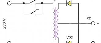
Electronic matching unit
If we are talking about a modern car with complex electronic components, the first option for connecting a trailer will not be the best choice. The control unit tests the rear optics. When it determines that it is consuming more current, it will display an error message. In such cases, the so-called “matching block” is used. It is also used in the case of transmitting control signals via a multiplex bus.
The wiring is connected to signal circuits, only in this case the signals to the lighting equipment of the towed device come not from the car, but from the matching unit, and its presence is not perceived by the electronics. Additionally, the unit must be connected to a used car.
Universal connection diagram for car trailer socket - second method
Connecting the towbar for cars with an electronic control unit is carried out in a completely different way. It provides for connecting the towbar electrics through a special matching device. It is a connecting element between the electronic control system and the rear optics and allows the control unit to recognize additional electrical equipment. Depending on which trailer socket pinout is used, the corresponding trailer connection diagram is used.
Connecting the towbar socket to a car with an electronic control unit is best done by an experienced auto electrician. He will be able to correctly connect the multiplex bus and test the operation of electrical equipment in different modes. If you have the appropriate preparation, you can try to make the connection yourself.
Do not neglect the electrical connection of a car trailer. This is a mandatory requirement that ensures the safety of the vehicle, as well as all other road users. Remember that the absence of side lights, improper operation of turn lamps and brake lights can not only cause a fine, but also cause an emergency. Before setting out on the road, visually check the proper condition of the electrical wiring and take a few minutes to check the operation of the trailer's electrical equipment.
Materials for connecting the tow bar
We go to a car store or car market and buy the materials necessary for installation and connection:
- socket housing for tow bar with cover and rubber O-ring. We pay attention to the normal fit of all parts of the case, the absence of play or the pressed brass contacts dangling in the sockets, we check the threads, the condition of the fastening screws on the terminals;
- high-quality single-core wire used in car electrical wiring, wire cross-section not less than 1.5 mm²;
- connecting blocks, it is better to use a model with fuse sockets;
- polypropylene or metal corrugated hose for insulating wiring harnesses - 2-3 meters, and a couple of dozen plastic mounting clamps for fixing wiring harnesses;
- silicone gasket, choose color and manufacturer to suit your taste.
Features of the socket connection
To connect the towbar to the vehicle's electrical wiring, we recommend using stranded copper wire. The ideal option is a wire in which each core has a cross-section of at least 1.5 square meters. mm. The wire must have a double layer of insulation.
After connecting the trailer according to our diagram and checking the functionality of its lighting equipment, it is advisable to take care of protecting the internal elements of the outlet from moisture. It would be a good idea to use graphite lubricant, which will also prevent oxidation of the contacts.
Operating rules
In order for the part to last long enough and to avoid problems with the traffic police, the following rules for operating a trailer hitch on a vehicle must be observed:
- Before installing the trailer hitch, you should clarify whether the vehicle manufacturer provides for the installation of this equipment. If you do not do this and do not register changes to the design of the car, then problems with the traffic police may arise.
- When transporting a trailer with a gross weight close to the maximum value, the maximum permissible vehicle speed should not exceed 90 kilometers per hour.
- Regularly check the tightness of the trailer hitch connections. Experts recommend carrying out this operation. Experts recommend carrying out this operation every 1000 km of the vehicle.
- To protect a product that has not been used for a long time from destruction, and to protect it from the negative effects of the environment, use a protective cap and a special lubricant.
- Scratches and chips that occur on the part during operation are covered with a special restorative composition. In addition, moisture, salt and dirt should be removed from it regularly. This is necessary to protect the trailer hitch from corrosion.
With careful use of the trailer hitch, the part will last 10 years.