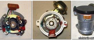
↑ Ignition distributor 0.3706
1 — ignition distributor roller; 2 — wire for supplying current to the ignition distributor; 3 — cover fastening latch; 4 — vacuum regulator housing; 5 - diaphragm; 6 — vacuum regulator cover; 7 — vacuum regulator rod; 8 — pipe for the vacuum hose from the carburetor; 9 — lubricating wick (filt) of the cam; 10 — support (driven) plate of the ignition timing regulator; 11 — ignition distributor rotor; 12 — side electrode with a terminal for the wire to the spark plug; 13 — ignition distributor cover; 14 — central terminal for the wire from the ignition coil; 15 — central carbon electrode with a spring; 16 — central contact of the rotor; 17 - resistor for suppressing radio interference; 18 — external contact of the rotor; 19 — driving plate of the centrifugal regulator; 20 — weight of the centrifugal ignition timing regulator; 21 — lever axis; 22 — breaker cam; 23 — breaker lever; 24 — stand with breaker contacts; 25 — breaker contacts; 26 — movable breaker plate; 27 - capacitor; 28 — ignition distributor housing; 29 — roller oil deflector clutch; 30 — bearing locking plate; 31 — bearing of the movable plate of the breaker; 32 — oiler body; 33 — screws for fastening the rack with breaker contacts; 34 — terminal clamp screw; a — groove for distinguishing ignition distributors 30.3706; b - groove for moving the stand with contacts Fig. 8–22. Ignition distributor 0.3706: 1 — ignition distributor shaft; 2 — wire for supplying current to the ignition distributor; 3 — cover fastening latch; 4 — vacuum regulator housing; 5 - diaphragm; 6 — vacuum regulator cover; 7 — vacuum regulator rod; 8 — pipe for the vacuum hose from the carburetor; 9 — lubricating wick (filt) of the cam; 10 — support (driven) plate of the ignition timing regulator; 11 — ignition distributor rotor; 12 — side electrode with a terminal for the wire to the spark plug; 13 — ignition distributor cover; 14 — central terminal for the wire from the ignition coil; 15 — central carbon electrode with a spring; 16 — central contact of the rotor; 17 - resistor for suppressing radio interference; 18 — external contact of the rotor; 19 — driving plate of the centrifugal regulator; 20 — weight of the centrifugal ignition timing regulator; 21 — lever axis; 22 — breaker cam; 23 — breaker lever; 24 — stand with breaker contacts; 25 — breaker contacts; 26 — movable breaker plate; 27 - capacitor; 28 — ignition distributor housing; 29 — roller oil deflector clutch; 30 — bearing locking plate; 31 — bearing of the movable plate of the breaker; 32 — oiler body; 33 — screws for fastening the rack with breaker contacts; 34 — terminal clamp screw; a — groove for distinguishing ignition distributors 30.3706; b - groove for moving the stand with contacts
Adjusting the contacts of the breaker-distributor
Before we begin to describe the sequence of adjusting the contacts of the breaker , we should briefly recall the purpose of the contacts.
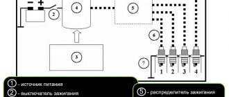
The fact is that in order to ensure engine starting and operation by the ignition system , high and low voltage currents must be generated. The sources of low voltage direct current in a car are a battery and an alternator with a built-in electronic silicon three-phase rectifier.
On its way, low voltage current from the battery or generator passes through the ignition switch to the primary winding of the ignition coil, where it creates a magnetic force field. To “produce” a powerful spark, which will subsequently ignite the compressed working mixture, a high voltage is required, reaching 12-24 kV.
The secondary winding of the ignition coil can reproduce such a high voltage current, but for this, the low voltage current circuit in the primary winding of the coil must be interrupted, its magnetic force field must be reduced accordingly and, crossing the turns of the secondary winding, induce a high voltage current in them.
The purpose of the contacts of the breaker-distributor is to provide the necessary intermittency in the low-voltage current circuit, and this intermittency is achieved only if the gaps between the moving and fixed contacts of the mechanical breaker are correctly set.
The gaps between the contacts are usually checked every 10 thousand km. mileage The condition of the contacts and the force with which they are pressed against each other are also monitored.
The gap should be equal to 0.37 - 0.43 mm, and the force of the spring pressing the contacts of the breaker should be equal to 550 ± 50 gf. Before adjusting the gap in the breaker contacts, use the starting handle to turn the crankshaft until the contacts open.
Ignition distributor
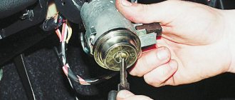
To perform the operation of checking and adjusting the gaps between the contacts, it is necessary to remove the cover of the breaker-distributor without pulling out the high voltage wires from it. When starting the operation, do not forget to lubricate the wick 4 of the distributor cams.
Engine oil is used as a lubricant, and an engine oil level indicator (dipstick) can be used as a tool, since it always holds enough oil to wet the wick (2-4 drops are required). To adjust the gaps of contacts 2, you need a screwdriver and an ignition gauge.
Adjustments must be made in the following order:
- loosen screw 6
- insert a screwdriver into the groove and move the contact post of the breaker to the desired gap size;
- tighten screw 6 until it stops.
If the contacts are dirty, wipe them with a clean cloth soaked in gasoline. If during the inspection process you find uneven wear of the contacts, they must be cleaned with a “velvet” thin file.
The contacts require gentle handling, so sandpaper and glass paper should not be used for cleaning.
Having put the contacts in order, reinstall the cover of the breaker-distributor. Pay special attention to installing the cover.
Remember, the slightest misalignment of the lid and slider 5 will immediately break it.
↑ Procedure for checking the gap
It is necessary to check the gap between the contacts of the breaker in the following order.
- Place the gear shift lever in neutral and apply the parking brake to the vehicle.
- Remove the cover from the ignition distributor and, by rotating the crankshaft, set the breaker cam to a position in which the breaker contacts are maximally open.
- Check the gap size with a feeler gauge; if it goes beyond 0.35–0.45 mm, then loosen screws 33, insert the blade of a screwdriver into groove “b” and turn the breaker stand to the desired amount.
- After adjustment, tighten screws 33 until they stop.
Adjusting contact gaps VAZ 2106-2103
Has your car's fuel consumption increased, the engine starts poorly and does not idle stable, is the car clearly not developing the required power? All these signs indirectly indicate that the angle of the closed state of the contacts (UZSK) is broken. The gap between the breaker contacts is a very important parameter that needs to be monitored.
Adjustment of the ultrasonic vibrating system must be carried out using special equipment, so it is recommended in such cases to use specialized workshops. As they say at home, UZS is set in case of emergency, that is, when it is necessary to determine the cause of a malfunction or, for example, when independently setting the ignition timing. Usually the ultrasonic vibrating system is set approximately according to the gap between the contacts.
We will consider a method for adjusting the contact gap of the VAZ 2106 with our own hands, that is, we will simply set the required gap between the contacts of the breaker, so that you simply understand the principle of adjustment and you can, if something happens, navigate yourself when performing repair work to set the ignition timing.
Let's get started:
- Prepare a set of probes, we will need a probe with a thickness of 0.40mm.
- Unfasten the holders from the ignition distributor cover and remove it.
- Remove the ignition distributor rotor by unscrewing the two screws securing it.
- Using a special wrench, turn the crankshaft to such an extent that the breaker cam is in a position in which the breaker contacts are maximally open.
- Check the gap between the contacts of the breaker; if the gap is larger or smaller, then loosen the screws securing the contact stand one by one and slightly moving the stand with a screwdriver, achieve the optimal gap between the contacts of the breaker.
- Tighten the rack mounting screws and install all parts in the reverse order of removal.
At this point, the repair work to adjust the gap between the contacts of the breaker on the VAZ 2106 car has been completed.
On a note:
- Always, after adjusting the ultrasonic vibrating system, the ignition timing is off, adjust it.
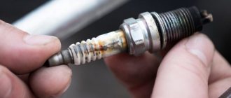
- Before adjusting, pay attention: as a rule, as a result of work, a tubercle is formed on the surface of the fixed contact, which must be removed using a file. And on the moving contact, a depression is formed; you should not touch it. If the contacts are too worn out and when they are closed, they do not completely touch the planes or touch askew, then it is necessary to replace the contact board.
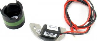
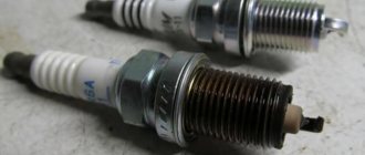
Burning due to excessively powerful sparking
The big disadvantage, the disadvantage of CG, is the sparking process, which cannot be eliminated in any way. However, significant minimization of sparking can be achieved by connecting a capacitor. Yes, and be sure to set the correct gap.
Note. The KG gap should be set so that it does not exceed 4/10 of a millimeter. However, on VAZ cars this gap may be slightly larger.
More details about distributor clearances in domestic versions of cars can be found in the table.
| ICE model | Distributor | Contact gap, mm | UZSK, city |
| VAZ 2101-2106 | R-125 or R-125D | 0.4 plus/minus 0.03 | 55 plus/minus 3 |
| ZMZ-24 "Volga" | R-119B | 0.4 plus/minus 0.05 | 39 plus or minus 3 |
| UMZ-412 "Moskvich" | R-118, R-147 | 0.4 plus/minus 0.05 | 43 plus/minus 4 |
| MeMZ-968, -966 | R-114, R-114B | 0.4 plus/minus 0.05 | 43 plus/minus 4 |
Article on the topic: What is the best way to flush the engine cooling system?
Experts say that if you increase the gap above standard values, you can get rid of sparking. In other words, if the distributor contacts are burning, increasing the gap will be the optimal measure to eliminate the problem. However, this also has its drawbacks. In particular, the angle decreases, which leads to a decrease in the additional current voltage.
KG gaps and their adjustment
It’s easy to guess - if the KG gap is incorrectly set and there is strong sparking, normalization can be achieved if the gaps between the contacts are slightly increased, but not by much.
Excessive sparking, we recall, can be observed not only in the distributor CG, but also on the rotor. When the distributor rotates, high-voltage current is transmitted from the central contact to the side contact. And in this case, if the settings are made incorrectly, the voltage of the additional, secondary voltage can be significantly reduced.
The principle of operation of the contact group
The CG or contact group functions in a special way. It is constantly under tension, which in most cases explains the burning. To minimize burning, and therefore additional current, a capacitor is connected. The latter is located at the bottom of the classic layout distributor.
Burning due to a powerful spark
In the process of opening the CG, a spark appears in the gap, sometimes too powerful. This spark charges the capacitor. However, a powerful spark appears only at the moment the CG opens, but the spark is minimized, its strength is reduced to nothing as the gap opens completely or increases. And at this very time, the process of discharging the capacitor, storage tank or heat exchanger (as it is also called) begins. At this time, voltage goes directly to the coil, or rather, to its main winding.
If you try to deepen your knowledge, you can also pay attention to the fact that in the process a current pulse is created, allowing the magnetic flux to disappear. But the most important thing is not this, but the fact that with the help of a pulse it is possible to achieve a current with a higher voltage on an additional winding.
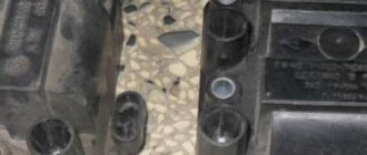
Distributor capacitor
Capacitor capacity may vary. It depends on the specific make or model of car. For example, in domestic VAZ models the capacitance of the part is 0.2-0.25 microfarads.
When the value increases or decreases, this necessarily leads to a decrease in the current on the additional winding.
A classic disadvantage of contact ignition systems is that high-voltage current passes through the ignition system. A priori, the element wears out several times faster than expected. This reduces the reliability of the system.
In order to somehow eliminate the shortcomings of the contact distributor, the engineers provided for automatic configuration of this system. For example, on all VAZ classic systems there is an automatic increase in spark energy, which “cleanses” the system. However, this only happens at average engine speeds.
Contact and non-contact distributors
Related article: Nissan GT-R, Jeremy Clarkson review
An increase in voltage a priori makes the entire system less sensitive to both the quality of the fuel and the condition of the SZ electrodes.
Although an amateur, it is a brilliant remark: it is possible to improve the contact system, but it would be better to abandon it altogether and switch to an electronic one. It is, of course, possible to achieve passing a current with a minimum value through the CG, which would not switch in the main circuit, but control it. But this is difficult and only accessible to professionals.