From the secondary winding of the ignition coil, a high voltage is supplied to the central electrode of the distributor, which is transmitted using a slider to the side electrodes of the distributor. The speed of rotation of the slider is equal to the speed of rotation of the camshaft and relates to crankshaft revolutions in a ratio of 1:2. The side electrodes of the distributor cover are connected to the spark plugs via high-voltage wires. The main disadvantage of this system is the difficulty in ensuring timely supply of voltage to the spark plugs at different engine speeds and operating modes. This problem was partially solved by the use of a centrifugal and vacuum ignition timing regulator, and subsequently by the use of electronic units, but did not completely solve the problem. In addition, the system has many connections and wearing contacts, which significantly reduces reliability.
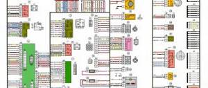
Typical ignition system
Ignition system components
On the technical side, the ignition system is part of the engine electrical equipment complex.
Structurally, it consists of the following elements:
- Battery or other power source. It supplies a low voltage of 12 volts to the network.
- Switch. When you turn the key, the switch closes and low voltage flows into the energy storage device.
- Energy storage. There are two types: inductive (a transformer-type ignition coil that converts low voltage into high voltage up to 30 thousand volts) and capacitive (capacitor).
- Energy storage and distribution control unit. Depending on the type of ignition system, this may be a chopper, a transistor switch, or an ECU (electronic control unit).
- Distributor. This unit can be mechanical or electronic. It supplies certain candles with energy at a given point in time.
- High voltage circuit wires. They supply high voltage to the electrodes of the spark plugs.
- Spark plug.
The operation of the ignition system is based on the following principle: when low-voltage voltage is supplied to the network, energy is accumulated and converted, which is then distributed among the spark plugs, on the electrodes of which a spark is formed, provoking the ignition of the air-fuel mixture.
Contactless ignition system is easy to install
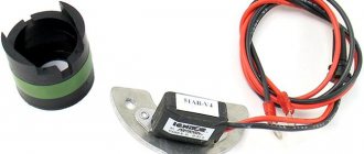
To mount and configure the above electronic motorcycle accessory you only need a couple of hours within one day. And why spend more time on attaching a Hall sensor, several wires and a new switch. Moreover, there is no need to modify anything on the bike’s engine generator. Simply remove the old contacts and install elements of the contactless ignition system Izh, Ural, etc.
The modulator plate must be securely mounted on the rotor of the motorcycle power unit. It should pass clearly in the middle of the Hall indicator slot. The washers will also be used. You can look at the drawing in this section of the article yourself, which will confirm the ease of installation. The contactless ignition circuit is also available here in color (look at the very bottom of the page). From it, anyone can figure out what's what.
Note that the presence of a voltmeter is not at all necessary. You can safely throw away this accessory, since demonstrating the voltage in the on-board network is unlikely to give you anything in practice. This is extra weight (and, accordingly, a load for the iron horse). The whole secret of the successful operation of contactless ignition on the Izh Jupiter 5, which is very often tuned with this system, lies in the modulator plate and the Hall sensor.
That is why the lion's share of the time of the installation process of a contactless ignition circuit is spent on its installation. If there are gaps in the sparking process, it is often possible that the modulator shutter, which closes the magnetic flux, is designed incorrectly. Therefore, its location relative to the sensor must be carefully checked. When open, this system accessory must not block the magnet or magnetic circuit. When closed, the modulator will completely block both of them. It is better to make the modulator of the contactless ignition circuit in the form of a disk with a cutout. For 1-cylinder engines, the cutout angle on the modulator should be about 120 degrees. For 2-cylinder motors, the cutout angles are 60 degrees, respectively.
Even before installing the BSZ on Jupiter 5, Planet 4 or other bikes, you need to make sure that there is no excess play on the generator shaft. Even contact ignition does not go well with backlash.
Features of the contact system
Historically, the contact system was one of the first and today it can only be found on older car models. In such designs, the formation of high voltage occurs in a transformer coil, and its distribution to the spark plugs is carried out mechanically - by closing and opening the circuit contacts with a breaker-distributor.
Contact ignition system device
In addition to the main elements, such systems include a centrifugal ignition timing regulator, which is necessary to convert the ignition timing relative to the crankshaft speed. It consists of two weights acting on a mobile plate in contact with the cam mechanism of the breaker.
Ignition timing is a certain position of the crankshaft at which high voltage is supplied to the spark plugs. In this mode, ignition occurs until the piston reaches top dead center, which ensures the most efficient combustion of the air-fuel mixture.
Also in the contact circuits, a vacuum ignition timing regulator is used, which changes the timing angle according to the operating mode (load) of the engine. It is connected to the cavity located behind the throttle valve, and when you press the gas pedal, it changes the advance angle depending on the magnitude of the vacuum.
When the contacts are closed, a low voltage is applied to the primary winding of the coil, where energy is accumulated and at the moment the contact opens, a high voltage is formed on the secondary winding. The energy then goes to the ignition distributor and then to the corresponding spark plug.
If the load on the power unit increases, the rotation speed of the chopper-distributor shaft increases, and the weights of the centrifugal regulator diverge, changing the position of the plate. This promotes earlier opening of contacts, which increases the advance angle. When the load on the engine decreases, the reverse process occurs. What are the differences between a contact-transistor ignition system? The next generation of the ignition system was a contact-transistor one, which involves installing a transistor switch coil in the primary circuit. It allows you to reduce the current in the low voltage winding, which increases the service life of the contacts.
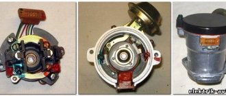
What elements does the BSZ consist of?
BSZ is a modernized transformation of KSZ. In it, the mechanical breaker is replaced by a sensor. Today, most domestic models and foreign cars are equipped with such ignition.
Note. The BSZ can act as an additional element of the KSZ or function completely autonomously.
The use of BSZ allows one to significantly increase the power parameters of the power plant. It is especially important that fuel consumption is reduced, as well as CO2 emissions.
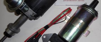
Ignition coil BSZ
In a word, the BSZ includes a number of components, among which a special place is occupied by a switch, pulse regulator, switch, etc.
BSZ is a device that is similar to a contact ignition system, but has a number of positive aspects. However, according to some experts, it is not without its drawbacks.
Let's look at the main elements of the BSZ to get a more overview.
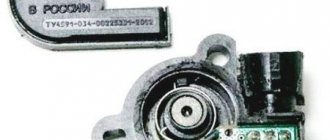
Hall Sensor
Pulse regulator or DEI* - this component is designed to create low voltage electrical pulses. In the modern technology industry, it is customary to use 3 types of DEI, but in the automotive industry only one of them has found widespread use - the Hall sensor.
As you know, Hall is a brilliant scientist who was the first to come up with the idea of rationally and effectively using a magnetic field.
This type of regulator consists of a magnet, a semiconductor plate with a chip, and a shutter with recesses that actually transmit the magnetic field.
Note. The shutter has slots, but in addition to this, there is also a steel screen. The latter does not sift anything, and thus an alternation is created.
DEI – electrical impulse sensor
Hall Sensor
The regulator is structurally connected to the distributor, thereby creating a device of a single type - a regulator-distributor, outwardly similar in many functions to a breaker. For example, both have a similar crankshaft drive.
KTT
A transistor-type switch (CTS) is a useful component that serves to interrupt electricity in the ignition coil circuit. Of course, CTT functions in accordance with DEI, forming together with the latter a single and practical tandem. The electrical charge is interrupted by unlocking/closing the output transistor.
Coil
And in the BSZ the coil performs the same functions as in the KSZ. There are certainly differences (detailed below). In addition, an electrical switch is used here to interrupt the circuit.
Article on the topic: How to clean the car air filter?
The BSZ coil is more reliable and better in every way. The start-up of the power plant is improved, and the operation of the engine in different modes becomes more effective.
How does BSZ work?
The rotation of the crankshaft of the power plant affects the distributor-regulator tandem. In this way, voltage pulses are generated and transmitted to the CHP. The latter creates a current in the ignition coil.
Note. You should know that in auto electrics it is customary to talk about two types of windings: primary (low) and secondary (high). A current pulse is created in low voltage, and high voltage is created in high voltage.
BSZ functioning scheme
Next, the high voltage is transferred from the coil to the distributor. In the distributor it is received by the central contact, from which the current is transmitted through all armored wires to the spark plugs. The latter ignite the combustible mixture, and the internal combustion engine starts.
As soon as the crankshaft speed increases, the CROS* regulates the SOP**. And if the load on the power plant changes, then the vacuum sensor is responsible for the OZ.
TsROZ – centrifugal ignition timing regulator
UOZ – ignition timing angle
Of course, the distributor itself, be it old or new, is a mandatory element of the car’s ignition system, contributing to the appearance of high-quality sparking.
The new model distributor eliminates all the shortcomings of the contact distributor. True, a new one costs an order of magnitude more, but it usually pays off later.
As was written above, when operating the BSZ, a new distributor is used that does not have a contact group. Here the role of a breaker and connector is performed by a CCT and a Hall sensor.
Contact-transistor ignition system
The next generation of the ignition system was a contact-transistor one, which involved installing a transistor switch coil in the primary circuit. It allows you to reduce the current in the low voltage winding, which increases the service life of the contacts.
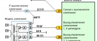
ignition distribution systems appeared , that is, not moving. This became possible thanks to the switching of high-voltage coils by electronic units. This system completely adjusts the moment of spark formation depending on the speed and load on the engine. There are several schemes for implementing static distribution. In the first option, there are two cylinders with ignition timing shifted by 360 degrees. the crankshaft simultaneously receives high voltage from the ignition coil. In this case, sparking occurs simultaneously in two cylinders. Since the spark plugs are connected in series to the secondary winding of the ignition coil, the spark discharge on the spark plugs will be the same discharge in the series-connected spark gaps, and will flow in the same direction. Consequently, if on one spark plug of a pair the spark discharge arc is directed from the central electrode to the side electrode, then on the other spark plug, on the contrary, from the side to the central one. At the same time, the spark energy will be different. This is due to the environment in which the spark was generated. When one spark plug is in the cylinder where the compression stroke occurs, the other is in the cylinder where the end of the exhaust stroke occurs. High pressure is applied to one of the spark plugs and it ignites the mixture; the spark on the other spark plug jumps to idle. The energy of a spark discharge that does not ignite the mixture is the same as the total loss of current in the spark gaps between the rotor and the side contacts with high-voltage ignition distribution. The picture changes to the opposite after one beat. This method uses one coil in a two-cylinder engine and two coils in a four-cylinder engine, working in pairs 1 - 4 and 2 - 3 cylinders. The coils are controlled by a two-channel switch at the command of the controller. Often the coil control key is built into the controller.
Contact-transistor ignition system
Due to the installation of a transistor, the voltage supplied to the spark plugs is 30% greater than in a classic contact system. The gap between the electrodes and, as a consequence, the length of the spark is also larger, which means that the contact area with the air-fuel mixture also increases, which contributes to its complete combustion. In a contact-transistor ignition system, the breaker acts not on the coil, but on the switch.
When you turn the key, two types of currents begin to pass through the transistor:
- management;
- main current of the primary winding.
When the contacts open, the control circuit current disappears and the transistor turns off, preventing primary current from flowing. At this moment, the magnetic field forms a high voltage on the secondary winding. To speed up the turn-off of the transistor, a pulse transformer can be installed in a contact ignition system of this type.
tartor › Blog › Car ignition system.
The main purpose of a car's ignition system is to supply a spark discharge to the spark plugs at a certain stroke of the gasoline engine.
For diesel engines, ignition refers to the moment of fuel injection during the compression stroke. In some car models, the ignition system, namely its pulses, is supplied to the control unit of the submersible fuel pump. The ignition system, as it develops, can be divided into three types. Contact ignition system, the pulses of which are created during the operation of the contacts to break. Non-contact ignition system, control pulses are created by an electronic transistor control device - a switch (although it is correct to call it a pulse generator). The microprocessor ignition system is an electronic device that controls the ignition timing, as well as other vehicle systems. For two-stroke engines without an external power source, magneto-type ignition systems are used. It is based on the principle of creating an EMF when a permanent magnet rotates in the ignition coil along the trailing edge of the pulse. ✔ Ignition system design
All of the above types of ignition systems are similar to each other, they differ only in the method of creating a control pulse. So the ignition system includes:
1. The power source for the ignition system is the battery (when the engine starts) and the generator (while the engine is running).
2.The ignition switch is a mechanical or electrical contact device that supplies voltage to the ignition system, or in other words, the ignition switch. As a rule, it performs two functions: supplying voltage to the on-board network and ignition system, supplying voltage to the vehicle starter solenoid relay.
3. Energy accumulator - a unit designed to accumulate and convert energy sufficient to cause an electrical discharge between the electrodes of the spark plug. Conventionally, energy storage devices can be divided into inductive and capacitive.
• The simplest inductive accumulator is an ignition coil, which is an autotransformer; its primary winding is connected to the positive pole and through an interruption device to the negative one. During operation of a breaking device, such as an ignition cam, a self-induction voltage arises in the primary winding. An increased voltage is generated in the secondary winding, sufficient to breakdown the air gap of the spark plug.
• A capacitive accumulator is a container that is charged with increased voltage and at the right moment transfers its energy to the spark plug
4. Spark plugs are a device with two electrodes located at a distance of 0.15-0.25 mm from each other. It is a porcelain insulator mounted on a metal thread; in the center there is a central conductor, which serves as an electrode; the second electrode is the thread.
5.The ignition distribution system is designed to supply energy from the accumulator to the spark plugs at the right moment. The system includes a distributor and/or switch, and an ignition system control unit.
• Ignition distributor (distributor) – a device for distributing high voltage along the wires leading to the cylinder spark plugs. Usually the distributor also contains a cam mechanism. Ignition distribution can be mechanical or static. The mechanical distributor is a shaft that is driven by the engine and, using a “runner,” distributes the voltage along high-voltage wires. Static ignition distribution implies the absence of rotating parts. With this option, the ignition coil is connected directly to the spark plug, and control comes from the ignition control unit. If, for example, a car engine has four cylinders, then there will be four coils. There are no high-voltage wires in this system.
• The switch is an electronic device for generating control pulses for the ignition coil, it is connected to the power circuit of the primary winding of the coil and, upon a signal from the control unit, interrupts the power supply, resulting in a self-induction voltage.
• The ignition system control unit is a microprocessor device that determines the moment at which an impulse is sent to the ignition coil, depending on the data from the crankshaft position sensors, lambda probes, temperature sensors and the camshaft position sensor.
6.High-voltage wire is a single-core wire with increased insulation. The inner conductor can be in the shape of a spiral to eliminate interference in the radio range.
✔ Operating principle of the ignition system
Let's consider the principle of operation of the classical ignition system. When the distributor drive shaft rotates, the cams are activated, which “break” the 12 volts supplied to the primary winding of the autotransformer (bobbin). When the voltage on the transformer disappears, a self-inductive emf appears in the winding, and accordingly a voltage of about 30,000 volts appears on the secondary winding. High voltage is supplied to the ignition distributor (slider), which alternately rotates and supplies voltage to the spark plugs depending on the operating cycle of the internal combustion engine. The high voltage is sufficient for the spark discharge to break down the air gap between the spark plug electrodes.
Ignition timing is necessary for more complete combustion of the fuel mixture. Due to the fact that the fuel does not burn immediately, it must be ignited a little earlier, before reaching TDC. The timing of the spark must be precisely adjusted, because otherwise (early or late ignition) the engine will lose its power and increased detonation is possible.
Operating principle of the contactless system
An evolutionary continuation of the transistor-contact system is contactless ignition. In such designs, a special pulse sensor is installed instead of a breaker. This makes it possible to increase the service life of the ignition system due to the absence of malfunctions associated with the breaker contacts.
The sensor generates low voltage electrical pulses. It comes in three types:
- Hall Sensor . The design of such a sensor includes a permanent magnet and a semiconductor wafer equipped with a microcircuit.
- Inductive . The principle of its operation is based on changing the induction value of the sensing element depending on the size of the gap between the sensor and a moving plate rotor acting on the magnetic field.
- Optical . It consists of an LED, a phototransistor and a matching chip. When light from the diode hits the phototransistor, the sensor supplies ground (minus power) to the switch. Blocking the flow of light provokes the disappearance of the current in the coil and contributes to the further formation of a spark.
Structurally, the pulse sensor is integrated into the distributor and is regulated by the engine crankshaft rotation mode. Interruption of the current in the primary winding of the ignition coil of the contactless system is also carried out by a transistor switch, but responding to sensor signals. When the crankshaft rotates, the sensor sends voltage pulses to the switch. The latter, accordingly, generates current pulses in the low voltage winding of the coil. When no current flows, a high voltage appears on the secondary winding, which is transmitted to the distributor and then through high-voltage wires to the desired spark plug. Changing the advance angle in a contactless ignition system is also performed by centrifugal and vacuum regulators.
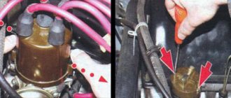
Design and principle of operation of the ignition coil
The coil has a fairly simple structure. It has two cylindrical windings: the primary, containing 100-150 turns of large-section wire, and the secondary, containing several thousand turns (up to 30,000) of small-section wire. Moreover, the turns of the primary winding are located on top of the turns of the secondary winding. Inside the windings there is a metal core.
This entire structure is placed in a cylindrical dielectric housing, the housing cover is non-removable, and the internal volume is usually filled with transformer oil (it ensures cooling of the coils during operation). There are several contacts on the cover (usually three): a central terminal from which high voltage is removed, and two side terminals to which low voltage current is supplied.
The operation of the ignition coil is based on the phenomenon of electromagnetic induction. In essence, the coil is a step-up transformer, the primary winding of which is supplied with low voltage current, and the secondary winding is removed with high voltage current. But in the coil, unlike conventional transformers, short pulses of electric current are converted, and, accordingly, electric pulses are also obtained at the output.
However, as you know, a transformer can only operate with alternating current, while cars use direct current. Moreover, a direct current also flows through the primary winding of the coil, which means that no current can arise in the secondary winding. Is there a contradiction here? In fact, everything is simple: the ignition coil works in conjunction with a breaker - a device that provides a pulsation of direct current and supplies fairly short electrical pulses to the primary winding. A pulse passing through the primary winding also excites a pulse in the secondary winding due to electromagnetic induction. Moreover, the peak voltage of the electrical pulse in the secondary winding will be the same number of times greater than the voltage in the primary winding, how many turns there are in the secondary winding relative to the primary.
It is important to note that the current conversion occurs precisely at the moment the breaker opens, that is, at the moment the primary winding of the coil is disconnected from the battery or generator. The voltage at this moment does not drop instantly, but over a certain (very short) period of time, and during this time, a high voltage current is induced in the secondary winding due to a change in the current in the primary winding - this pulse is supplied to the spark plug.
Since the conservation law operates in the coil, the current power in the secondary winding is almost equal (in fact, slightly less) to the current power in the primary winding. This means that the electrical pulse at the output has a high voltage, but a low current, and in the primary winding everything is exactly the opposite. That is why the primary winding is made of a large cross-section wire (since currents of tens of amperes flow through it), and the secondary winding is made of a very thin wire (currents in the secondary winding do not exceed a few microamps).
Often ignition coils have an additional resistance (resistor) connected in series with the primary winding. This resistor is made of an alloy whose electrical resistance changes depending on temperature: when heated, the resistance increases, when cooled, it decreases. Additional resistance is necessary to protect the coil at low engine speeds.
The fact is that at low speeds, direct current passes through the primary winding of the coil for quite a long time, and this leads to increased heating of the wire and negatively affects the core. Therefore, at low speeds the resistor heats up, its resistance increases, and this leads to a decrease in the current in the primary winding - this prevents overheating. As the RPM increases, the temperature drops, the resistance of the resistor decreases, and a higher current flows through the primary winding. When the engine starts, the resistance is bypassed (that is, closed by a wire) and does not affect the ignition system.
Electronic and microprocessor systems
The most modern system is considered to be electronic. It has no mechanical contacts, and therefore can also be called contactless. Electronic ignition is part of the engine management system.
In this system there is practically no voltage loss, as in the previous ones, and the operation of each spark plug does not depend on the work of other spark plugs, as in the first and second variants of static ignition. In addition, in this case, the ignition timing is precisely adjusted directly in each cylinder, which allows complete combustion of fuel, thereby reducing the emission of harmful substances into the atmosphere.
Electronic ignition system
There are two types of electronic contactless ignition systems:
- With distributor . In such a circuit, a mechanical ignition distributor is used, which supplies high voltage to a given spark plug.
- Direct ignition . With this scheme, high voltage is supplied to the spark plug electrodes directly from the coil.
In addition to the basic elements, the electronic ignition system includes:
- Input sensors . They record data about the current operating mode of the motor and supply it in the form of electronic signals to the control unit.
- Electronic control unit . It processes the signals and transmits the appropriate commands to the igniter.
- Actuator , or igniter. In fact, it is a transistor board that, in open mode, provides voltage supply to the primary winding, and in closed mode, cuts off and generates high voltage on the secondary winding of the coil.
Such systems can be equipped with one common (in designs with a distributor), individual (when energy is supplied directly to the spark plug) or dual ignition coils.
A type of electronic system is a microprocessor. It uses a whole complex of sensors, the signals of which are processed by the ECU. It calculates the optimal operating mode of the system at a given point in time. The advantages of this design are reduced fuel consumption and improved dynamic characteristics of the vehicle.
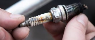
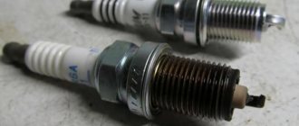
Spark test
This method is used at service stations. This requires special equipment. This could be a tester, stand or probe. We check the spark plugs that are on the engine with a tester. The engine must be running. We attach a special sensor to the spark plug wire. A candlestick chart will appear on the screen. By looking at this diagram, the operator will be able to know the condition of the spark plug. To identify a removed spark plug, a bench test is used. High voltage is applied to the electrodes. If at a certain pressure the spark between the electrodes of the spark plug is good, then such a spark plug is considered good. The spark plug can also be checked with a probe. Remove the high voltage wire from the tip of the spark plug, which is located on the motor, and place it on the probe sleeve. The tip is pressed against the motor. By pulling the trigger, high voltage pulses are applied to the spark plug. If the test lamp lights up, then such a spark plug can be considered working. In the same way, you can check a removed candle or a newly purchased one. Only the tip is pressed against the spark plug body. There is also another way to check a broken spark plug. This method can be used on the road if you only have one spark plug wrench. In this case, we put the high voltage wire on the central terminal of the spark plug. The spark plug needs to be brought closer to the engine. We crank the engine with the starter and check the spark at the spark plug electrodes. For safety reasons, wear gloves. See video.
If there is no spark at the spark plug electrodes, then you need to remove the carbon deposits on the spark plug. A heavily soiled candle is first placed in a solvent. Then we wash it with gasoline and dry it. You can use a hairdryer to dry it. Inspecting spark plugs in a simple way is approximate. It often happens that even a newly purchased spark plug passes the test, but the engine does not develop maximum power. There is an explanation for this. Producing a spark is highly dependent on the compression of gases in the combustion chamber. At increased pressure, the service plug produces a good spark. A spark plug that has an invisible defect will not produce a good spark. A candle tested in a simple way can be considered working.