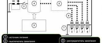
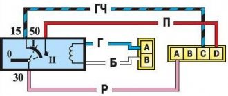
Modernization of the ignition system of VAZ – 1111 “Oka”
As you know, Oka cars are equipped with a rather imperfect 2-spark ignition system (similar to the options installed on some motorcycles). In general, the use of such a principle of organizing the ignition system cannot be called particularly flawed, however, due to the design features and the not very high quality of individual elements, it has a number of significant disadvantages. In particular, Oka owners are well aware of the existence of problems with starting these cars in winter (even a slightly “supercharged” battery simply cannot cope with maintaining a “push-pull” spark). The state of insulation between the high-voltage and low-voltage circuits of standard double-spark coils does not stand up to criticism either, as a result of which they very quickly fail due to moisture ingress and in damp weather. And, finally, such an unpleasant phenomenon as occasional “shots” in the muffler is also a consequence of the use of a two-spark ignition system - when an incompletely burned mixture is squeezed out by a piston into the intake manifold and, with the valves open, is ignited there by a “non-working” spark.
Be that as it may, the need to modernize the ignition system of the VAZ-1111 Oka is beyond doubt, and currently three main methods are most widespread:
- Introduction into the system of a standard VAZ 2108 distributor with high-voltage ignition distribution, one ignition coil and one switch (from the same place). In this case, two of the four curtains in the spark moment sensor are cut off, or unnecessary spark plugs are fixed in a neutral place in the engine compartment (it is prohibited to leave excess high-voltage wires without discharge).
- Installation of a combined two-spark unit in an imported or domestic version of the “all-in-one” type (switch + coil);
- Installation of the coils of two oil-filled ignition coils from the VAZ 2108, as well as two switches with the combination of their inputs to the output of the torque sensor.
In general, any of these methods allows you to achieve a certain positive result, although each of them is not without some disadvantages. So the first method reduces the overall reliability of the system due to the use of additional elements, namely a high-voltage distributor and several high-voltage wires. The second method is simply to use a more reliable version of the same two-spark system (if you can find decent equipment). Finally, the third method does not eliminate the problem of an “unnecessary” spark and is associated with energy expenditure on the second ignition coil.
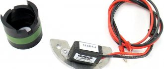
Based on the above, it makes sense to carry out a more original and effective modernization, namely, leave only one curtain in the original spark sensor and add a pair of Hall sensors to the system, spaced 180 degrees apart. In other words, it is proposed to implement the third option, eliminating its shortcomings by providing ignition in each of the cylinders using Hall sensors.
Preparatory work
- We are modifying the DMI unit to make it possible to connect two Hall sensors (by replacing the standard connector with a connector with the required number of contacts);
- we cut one of the DMI curtains under the base (the DMI will have to be disassembled), making sure that there are no shavings and crumbs of metal left that could get into the magnetic gap of the Hall sensors;
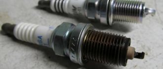
- we install high-quality injection spark plugs with a gap of 1.1 mm (BOSCH WR7D+X is suitable);
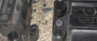
- we use domestic coils, type 27.3705;
- to compactly place the switch one above the other, we machine brass spacers to ensure a distance between the switches of approximately 27mm;
- “HORS” products with silicone caps are suitable as high-voltage wires. We additionally protect the wires from possible overheating with a heat-shrinkable tube.
Implementation Features
To ensure normal operation of the system, the hall sensors must be of the same type (from the same batch), otherwise the direction of the magnets will be disrupted and, as a result, the DMI curtain will be remagnetized. Simply put, you will have to abandon the original sensor.
Power wiring for plus 12V on the relay (in the standard version, blue-black) is carried out with a wire with a cross-section of at least 4 sq mm, while for switches a stranded wire of 2.5 mm is sufficient. It is better not to use standard wiring as there are significant losses on it.
For the signal part, you can take a shielded multi-core cable with a core cross-section of 0.2 mm (the screen will help get rid of interference).
The main difficulty in manufacturing a modernized ignition system is the need to accurately position the Hall sensors on the installation platform. The main problem is that the sensors must be installed with an accuracy of 0.1 mm opposite each other (relative to the circle passing through the centers of their slots). In any case, the sensor mismatch should not exceed 1 degree of crankshaft rotation. If this condition is not met, a significant drop in engine power is observed. For the same reasons, you should ensure that all elements of the system are securely fastened.
The ignition timing is set according to the standard method.
Tags ignition VAZ, OKA VAZ-1111
Similar materials
Checking and replacing the ignition coil of VAZ “OKA” 1111 1988-2008
- Repair manuals
- VAZ "OKA" 1111 1988-2008
- Checking and replacing the ignition coil
The vehicle may be equipped with an ignition coil type 29.3705 or 3012.3705.
The coil has two high-voltage terminals and supplies a spark to both cylinders simultaneously.
You will need: a 7 key, an ohmmeter.
| 1. Disconnect the wire from the “–” terminal of the battery. |
| 2. Open the hood. Remove the washer reservoir from the bracket by lifting it up and set it aside to gain access to the ignition coil mounting nuts. | 3. Disconnect the two high voltage wires from the coil terminals. |
| 4. Slide off the protective caps and disconnect the two wires from the low-voltage coil terminals. Remember or write down the order of connecting the wires: brown - to the rear terminal (along the direction of the car), and black and blue - to the front. | 5. Unscrew the three nuts securing the coil. |
| NOTE Please note that flat washers are installed under the nuts. |
| 6. Remove the ignition coil and wipe it with a clean cloth. |
| 7. To check the coil, measure the resistance of the primary and secondary windings. To measure the resistance of the primary winding, connect an ohmmeter to the low voltage terminals of the coil. The resistance should be (0.5±0.05) Ohm. | 8. To measure the resistance of the secondary winding, connect an ohmmeter to the high voltage terminals of the coil. The resistance should be (11.0±1.5) kOhm. If in at least one case the resistance is different from the specified value, replace the coil. |
| 9. Reinstall the coil and connect the wires to the low voltage terminals of the coil. |
| 10. Connect high-voltage wires to the coil terminals. The order in which they are connected does not matter. Reinstall the washer reservoir. |
↓ Comments ↓
VAZ-1111-11113 OKA
Section 1. VEHICLE STRUCTURE
General information about cars Vehicle registration data
Section 2. ENGINE
Possible engine malfunctions, their causes and solutions Useful tips Replacing the coolant Replacing the engine oil and oil filter Cleaning the crankcase ventilation system Setting the piston of the first cylinder to the TDC position of the compression stroke Adjusting the tension of the camshaft drive belt Replacing the tension roller Replacing the camshaft drive belt Removing, installation and troubleshooting of the flywheel Replacement of engine seal parts Cylinder head Adjustment of clearances in the valve drive Removal and installation of the engine Engine repair Lubrication system Cooling system Exhaust system Power supply system
Section 3. TRANSMISSION
Clutch Gearbox Front wheel drives
Section 4. CHASSIS
Front suspension Rear suspension
Section 5. STEERING
Inspection and check of the steering system on the vehicle Steering column Steering mechanism Steering linkage
Section 6.BRAKE SYSTEM
Checking and adjusting the brake system Replacing the brake fluid Bleeding the brake system hydraulic drive Master cylinder Brake vacuum booster Pressure regulator Replacing brake hydraulic hoses and pipelines Front wheel brakes Rear wheel brakes Parking brake
Section 7. ELECTRICAL EQUIPMENT
Fuses and relays Generator Starter Ignition system Lighting, light and sound alarms Windshield wipers and washers Engine cooling fan Instrument cluster Switches and switches
Section 8.BODY
Possible body malfunctions, their causes and solutions Replacement of buffers Hood Side door Rear door Rear view mirrors Seats Heater Body care
Applications
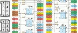
Appendix 1. Tightening torques for threaded connections Appendix 2. Fuels and lubricants and operating fluids Appendix 3. Basic data for adjustments and control Appendix 4. Filling volumes, l Appendix 5. Oil seals Appendix 6. Layout of rolling bearings Appendix 7. Car electrical diagram : 1 — side turn signal repeater; 2 — front direction indicator; 3 - headlight; 4 — electric motor of the cooling system fan; 5 — sound signal; 6 - sensor for turning on the electric motor
VAZ 1111 | Setting the ignition timing | Oka
Service and operation
Manuals → VAZ → 1111 (Oka)
Spark torque sensor location:
1 – spark torque sensor 2 – vacuum regulator 3 – hatch plug in the clutch housing 4 – engine auxiliary drive housing
| You will need |
|
Before starting work
Remove the air filter.
The ignition timing is checked and set at engine idle (at a crankshaft speed of 820–900 rpm). The angle should be within 1°± 1° BTDC.
If the ignition timing is incorrectly set, the engine overheats, does not develop full power, and detonation occurs.
| Check the ignition timing using the mark on the flywheel and the scale of the crankshaft rear oil seal holder (the rubber plug has been removed). When the marks on the flywheel are combined with the middle division (notch) on the scale, the piston of the first cylinder is installed at TDC. One division on the scale corresponds to 2° of crankshaft rotation. |
| The ignition timing can also be checked and set using the marks on the generator drive pulley and the front camshaft drive belt cover. The long mark corresponds to the installation of the first cylinder at TDC, the short mark to the ignition advance by 5° of crankshaft rotation. These marks are used to set the ignition timing on the stand. |
| EXECUTION ORDER |
1. Disconnect the hose from the vacuum regulator.
2. To check the ignition timing, connect the “+” terminal of the strobe to the “+” terminal of the battery, a.
3. . The ground clamp of the strobe light is connected to the “–” terminal of the battery.
4. Remove the tip of the high-voltage wire from the spark plug of the first cylinder and connect it to the strobe sensor in accordance with the instructions included with the strobe.
5. Remove the rubber plug from the clutch housing hatch.
6. Start the engine and direct the flashing strobe light into the clutch housing hatch.
7. When the ignition timing is correctly set, mark 1 on the flywheel should be between the middle division 2 and the previous division 3 of the scale. Otherwise, it is necessary to adjust the ignition timing.
8. To set the ignition timing, loosen the three nuts securing the spark timing sensor.
9. To increase the ignition timing angle, turn the sensor housing clockwise (the “+” mark on the flange of the sensor housing is towards the protrusion on the auxiliary drive housing. In this case, one division on the flange corresponds to 8° of crankshaft rotation).
10. To reduce the ignition timing angle, turn the sensor housing counterclockwise (the “-” mark on the sensor housing flange to the protrusion on the auxiliary drive housing). Tighten the sensor mounting nuts, check and, if necessary, repeat the ignition timing setting. Connect the hose to the vacuum regulator.
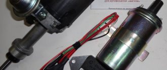
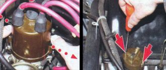
Oka ignition coil
Oka ignition coil , popularly referred to as a “bobbin”, is an element of a car’s ignition system, the main function of which is to generate an electrical impulse. In simple terms, this element generates a high-voltage discharge at the spark plug from a low-voltage discharge coming from the battery.
The Oka ignition coil is one of the weakest points of this car. This fact is explained not so much by poor quality assembly, but by ill-conceived design. As you know, the oka ignition coil is a two-spark coil, and very often motorists are faced with such trouble when the car does not start the first time. This disgrace can be explained by the fact that the distribution of the high-voltage discharge in the spark areas is random. The reason for this trouble is the lack of connection with ground inside the high-voltage part.
The ignition coil of a car, due to its imperfection, very often becomes the cause of a very undesirable and unpleasant phenomenon - loud shots from the car muffler. This is due to the fact that the two-spark coil system causes the working mixture to enter the manifold during the stroke of the piston, and then from the combustion chamber, with the exhaust valves open, to be ignited by a “non-working” spark. Resourceful motorists tried to solve this problem in many ways: they varnished the coil, covered it with silicone, and insulated it in every possible way, but such manipulations did not give any special positive results.
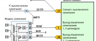
The oka ignition coil does not please drivers with its impeccable performance. But there is still a way out of this situation. The essence of the modification is to install two ignition coils from a VAZ 2108 instead of the “native” two-spark one. To do this you should prepare:
1) Two new coils from VAZ2108
2) Switch with connector from the same car
3) Electrical tape and wires
4) Self-tapping screws
2) The oka ignition coil will work much better if you carry out the following manipulations. First, remove the old ignition coil. Next, use self-tapping screws to attach two new coils to the right side member. The second switch should be installed next to the “native” one and securely fastened (you can put both switches together on one pin). The switches need to be connected in parallel. The only caveat is the need to lay an additional wire to contact (K) of one of the VAZ coils from the second switch. As a result, the power of the generated spark increases significantly, and you will be pleased with the end result. The spark plugs will also have to be replaced, since these elements will need at least a (1MM) spark gap.
More on the topic
- Cleaning spark plugs (0)
- Black carbon deposits on spark plugs (0)
- Depo Headlights (0)
- The starter clicks but does not turn (0)
- The starter turns but does not start (0)