GENERATOR
Generator Maintenance
To ensure reliable operation of the generator during operation, it is necessary to check the serviceability of the generator set using the ammeter on the instrument panel.
Check the radial clearance in the bearings by rocking the drive pulley - the bearings should not have noticeable clearance.
Every 48,000 km it is necessary to remove the generator from the engine, disassemble it, and also check the condition of the brushes and slip rings.
Remove the seals from the bearings and wash them with gasoline, then check their condition. If the bearings do not have noticeable clearance, then they may be suitable for further use. In this case, they should be filled with LZ-31 lubricant to 70% of their volume, otherwise the lubricant may squeeze out the seals. In the absence of the specified lubricant, you can use Litol-24 lubricant, however, the frequency of subsequent addition of such lubricant is no more than after 18,000-24,000 km of the vehicle. Check the condition of the brushes and the ease of their movement in the brush holders. If jamming is detected, stretch the spring or clean the hole.
Check the height of the brushes. Replace brushes with a height of less than 10-11 mm with new ones, having previously ground them to a radius of 15 mm. Clean the contact rings. If carbon deposits are found on the rings, they should be wiped with a clean, lint-free cloth lightly moistened with gasoline. In case of heavy carbon deposits on the rings, clean them with fine glass sandpaper. If there are grooves on the rings, the rings should be sharpened and the brushes replaced with new ones.
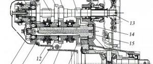
Transmission luaz 969m diagram
TUNING LUAZA TRANSMISSION.
So, let's begin. The topic is extensive, it begins with the engine and ends with gears in wheel reducers and wheel size.
So, what is the first thing most new luaz factories do? The first direction is to change the engine, the second is to change the wheels (more precisely, the tires, and therefore the wheels). What do they get as a result of the first and second actions? If the engine is replaced (and they install a more powerful one, usually a VAZ 2106 or 21213) they have excellent traction and speed (MeMZ 7.6 kgf*m, VAZ 12.4...12.9 kgf*m, maximum speed MeMZ - 4200, VAZ - 5400 rpm min), the maximum climbing angle with the MeMZ and standard IVK on the PP is 53 degrees, but with the VAZdvig, Lu on the PP can drive onto a vertical wall with a 300 kg trailer (and therefore the PP becomes practically unnecessary). Things are also better with speed, the maximum speed is about 90 on MeMZ and grows to 115 on VAZodvig. Disadvantages of installing a VAZodvig: the muzzle is very heavy even with the MeMZ, it becomes even 40 kg heavier, the rear axle shafts (which also twist with the MeMZ) twist much more often. The second direction is larger wheels. They usually use Cordiant 205/70 - 15. With them, Lu drives (with a standard transmission) 10% faster (the static radius of the Cordiant is 325 mm at IVka 292 mm), but it also pulls 10% worse, the climb you climbed on IVka and MeMZ, on Kordiantty with MeMZ it will become “unliftable” (maximum angle of ascent 46 degrees). Do angles of 53 and 45 degrees seem prohibitive to you? But this is an option for climbing an asphalt climb. In reality, firstly, the tires are lowered to 0.8 atm (otherwise the wheels break into the axle boxes on a 30-degree climb), and secondly, the ascent usually consists of soft turf with moss on top into which the car falls and all this adds resistance to movement. In practice, Lu with a MeMZ on Cordiants on a standard transmission stalls at a 30-degree incline (there is not enough traction), and with a VAZODvig and standard gears in the KR, the first slipping on the ascent will end with the rear drives twisting and falling out of the gearbox housing, regardless of what kind of tires worth it (I have no experience installing on Lou Zhigokoles 13″ so I don’t know how to twist with them). To stop the twisting of the drives (to relieve them), tuning gears with a large gear ratio (usually 1.6 or 1.784) are installed in the CD. What we get from the replacement is that the thrust increases by 24 (38)%, the load on the drives decreases, but the speed also drops by the same amounts. Cruising on asphalt from 70 on standard gears in the Kyrgyz Republic drops to 57 (51) by 1.6 (1.78), respectively (calculation: 70/1.6*1.294=56.6; 70/1.786*1.294=51.2 km /h) and the car becomes exclusively “forest” on asphalt outside the city they don’t drive at such speeds now. Therefore, they move on to the next stage of tuning, replacing the gears in the gearbox. In order to return at least some of the “asphalt character” to the car, they usually change fourth gear. Replace the standard 0.964 with 0.75 at 1.6 in the Kyrgyz Republic (0.71 at 1.78 in the Kyrgyz Republic). As a result, the cruising speed becomes 73 (70) (calculation: 56.6/0.75*0.964=72.8; 51.2/0.71*0.964=69.5), it becomes possible to move decent distances on asphalt, but the following problem arises - the gap in gear ratios between third and fourth gears becomes 88% at 0.75 and 99% at 0.71, i.e. in order to drive in fourth with 2400 rpm of the engine after switching, you need to spin it in third to 4500 rpm for 0.75 and 4800 rpm for 0.71. To overcome this problem, you have to change the third gear to a tuning gear of 1.208, and then everything becomes more or less balanced. The gaps between gears are approximately the same and tend to reduce the gaps between gear ratios as they increase. PP / 1st - (7.2/3.8) = 89%, 1st - 2nd (3.8/2.118) = 79%, 2nd - 3rd (2.118/1.208) = 75%, 3rd - 4th (1.208/0.75) = 61% in the case of the fourth 0.75 and (1.208/0.711) = 70% in the case of the fourth 0.71.
I recommend setting 0.75 to fourth (after replacing the gears in the KR with 1.6; 1.786) who has a MeMZ under the hood (spinning it up to 4000 rpm, after switching from third 1.208 to fourth 0.75 we have 2450 rpm, and from these speeds the MeMZ already pulls normally if the asphalt road is uphill, unlike 2100 after switching from the standard third 1.409, which is not enough for the normal traction of the MeMZ). And for those who have a VAZodvig under the hood, I recommend 0.71 (it can be spun up to 5400 rpm and after switching from the third 1.208 to the fourth 0.71 we have 3100 rpm, i.e. practically the value of the revolutions for the maximum torque of the VAZodvig, and not despite the greater load on the engine 0.75/0.71=5.6%, this is offset by a much greater torque of 12.5/7.6=65%, which leads to comfortable movement on almost any climb encountered on the highway). And lastly, there is the last unresolved problem with the LuAZ gearbox, low gear ratio ZX, which no one has been able to solve yet (and the gear ratio needs to be increased from 4.156 to 5.81 minimum).
STARTER
Installed on the right side of the engine.
Starter Maintenance
During operation, it is necessary to periodically check the condition of the clamps of the starter traction relay wires and the fastening of the starter to the engine.
Every 36,000 km, you need to remove the starter from the engine to thoroughly check and replace worn parts and components. It is recommended to carry out this work in special workshops or service stations.
If there are malfunctions in the operation of the starter, it is recommended to remove it, disassemble it and eliminate the malfunction.
To remove the starter, you need to disconnect the wires from the starter, unscrew the two nuts of the starter mounting studs, move the length of the starter studs towards the timing gear cover and remove it. Installation of the starter must be done in reverse order.
The history of the appearance of LuAZ cars
The general features of a civilian all-terrain vehicle can be seen in the appearance of the “front line transporter” (TPK) - this is what the LuAZ 967 amphibian was called in the documentation of military units, adopted for service in the late 60s.
For reference: In fact, the LuAZ 969 is a deep conversion of the military TPK. Only the concept is taken as its basis, and the main components and assemblies are designed anew. Only the electrical wiring of the LuAZ, as well as the power unit, were transferred from a military vehicle to a civilian vehicle.
In addition, the model under development, mass production of which began in 1967, also used:
- Conceptual development by NAMI, which had the index 049;
- Amphibian body structure without a propeller (movement through water is carried out by the energy of rotating wheels);
- Simplified “civilian suspension” of the front edge transporter (not providing for parachute landing).
For reference: the almost complete unification of parts and assemblies gave one undeniable advantage - the price of the car remained low. Therefore, in the case of LuAZ 969, exactly this decision was made - maximum compatibility with the military amphibian.
Differences in configuration
It is necessary to distinguish between externally identical LuAZ 969 cars:
- When assembling the first batches of cars, the plant experienced a shortage of components and assemblies, so the first 7,000 cars with a 4x2 wheel arrangement had only front-wheel drive. This configuration was designated by the LuAZ-969V index and was equipped with a MeMZ-969 power unit with a power of 30 hp;
- Beginning in 1971, the shortage of spare parts was overcome, the car got rid of the “B” prefix, but received 4x4 all-wheel drive.
There was also a little confusion in the designations of the car:
- In the documentation of 1964, the car was referred to as ZAZ 969;
- A year later he received the civil name "Volyn";
- Then its assembly was finally entrusted to the plant in Lutsk, and the car was named LuMZ 969V;
- LuAZ 969V – the final version of the name for the front-wheel drive configuration (4x2);
- LuAZ 969 is a 4x4 vehicle.
Modernization of LuAZ 969
In 1975, the plant launched the LuAZ 969A, which:
- Received an improved MeMZ-969A engine with a volume of 1.2 liters. and increased to 40 hp. power;
- Received a redesigned front end.
Since 1979, the plant switched to the production of LuAZ 969M, which has:
- A hydraulic vacuum booster and separate brake drive appeared;
- New doors with locks and rotary windows;
- New safety instrument panel;
- Driver and passenger seats from a Zhiguli car.
For reference: LuAZ wiring was constantly modified due to unstable supplies of components to the assembly line. Therefore, the manufacturer indicated the years of production of the vehicles on all diagrams.
LuAZ 969 cars were quite reliable and repairable, which allowed the owners to carry out maintenance and care with their own hands. However, almost all the years of production, the plant in Lutsk experienced problems with the supply of spare parts:
- In the early 90s, there were interruptions in the supply of ignition locks that function as an anti-theft system. The automaker was forced to equip the car with other locks, which led to a change in the electrical circuit;
- Not all cars were equipped with certain parts. Even cars of the same year could have differences in configuration;
- Of particular note is the wiring, which, due to low quality and frequent changes of suppliers, had differences in color and location inside the harnesses under the hood and in the cabin (see also the UAZ 3303 wiring diagram).
LIGHTS
Rice. Headlight: 1 - outer rim; 2 — rim fastening screw; 3 — rim seal; 4 — inner rim; 5 - diffuser; 6 - lamp; 7 - reflector; 8 — rubber gasket; 9 — adjusting screw; 10 — installation ring; 11 — body; 12 - spring; 13 — cover with contacts; 14 — connecting block; 15 - wire; 16 - tip
The headlights are equipped with a semi-dismountable sealed optical element, consisting of a reflector, diffuser glass and a flanged double-filament lamp.
Replacement of headlight bulbs must be done in the following sequence:
- remove the outer rim 1 secured with screw 2
- slightly unscrew the screws and remove the optical element, which is secured in the headlight by the inner rim 4;
- remove cover 13 with contacts;
- change the lamp;
- install the cover with contacts, the optical element, secure the inner and facing rims.
Adjusting the headlights FG 122 BV1
FG 122 BV1 headlights with European asymmetric low beam light distribution have a sharp boundary between the light and dark zones. Therefore, headlights must be adjusted very carefully so as not to dazzle oncoming drivers.
Rice. Adjusting the headlights
To adjust the headlights you need to:
- Place the equipped car with the driver on level ground against the screen located at a distance of 7.5 m from the car.
- Turn on the low beam and rotate two (on each headlight) adjusting screws 9 located at an angle of 90°. install the optical elements so that the boundary between the illuminated and unlit areas runs along line 2, and the inclined segments emerge from the intersection points of lines A and B with line 2, marked in the figure with the sign Each headlight is independently adjustable, and the light from another headlight should not illuminate the screen .
CIRCUIT BREAKERS
The following fuses are used in the vehicle electrical system:
- two thermobimetallic push-button type with a rated current of 20 A to protect the circuits of the heating system, body and engine compartment lighting, power socket, horn and brake warning system; installed on the instrument panel;
- three fusible fuses with a rated current of 6 A to protect the power circuits of instrumentation, a flashlight and a reverse switch and a turn signal relay (separately for the right and left sides), installed on wires under the instrument panel;
- thermobimetallic with a rated current of 3.5 A to protect the power supply circuit of the electric motors of the windshield wiper and washer; installed in the engine compartment on the bulkhead;
- a block of six fuses; installed in the body on the left side under the instrument panel.
Purpose of fuses:
- fuse A (8 A) - circuits of the sidelight and rear light of the left side (side marker), license plate lamp;
- fuse B (8 A) - circuits of the sidelight and rear light of the starboard side (side marker), lighting of instrumentation;
- fuse B (16 A) - left headlight high beam circuit;
- fuse G (16 A) - circuit of the main beam of the right headlight and the control lamp for turning on the main beam of the headlights;
- fuse D (8 A) - left headlight low beam circuit;
- fuse E (8 A) - low beam circuit of the right headlight.
Before replacing a blown fuse, eliminate the cause that caused its failure.
Thermal fuses are activated by pressing a button.
LuAZ-969 photo
Read further:
History of the Lutsk Automobile Plant
The most extraordinary appearance of the SsangYong XAV-Adventure concept car
New pickup truck - its performance at the auto show
KrAZ-6510
Mazda RX-7
HEATING
The heating system operates independently of the car engine, which allows it to be used to heat the body when the engine is not running.
Use of the heating system when the engine is not running should be short-term, as the battery may be discharged.
The installation is powered by the same gasoline as the car engine. Rules for turning on and off the heating installation. You can turn on the heating system both when parked and while driving. To enable it you need:
- Pull handle 8 of the switch towards you until the first click is heard.
- Wait 30 seconds, and then move the handle to the second position, pulling it towards you until it stops.
- Monitor (within 45-60 s) the moment when indicator light 20 with a green light filter on the instrument panel lights up. Illumination of the control lamp and its continuous burning indicate normal operation of the heating installation. If the control light does not light up within 1.5 minutes after turning the switch to the second position, the heating installation should be turned off, the fault should be identified and eliminated. To turn off the heating installation, the switch handle must be pushed all the way away. In this case, the control light continues to light for 3-5 minutes and then goes out.
The heating system can only be put back into operation after the indicator light goes out.
To ensure heating of the body and blowing of the windshield, handle 7 of the damper axis must be in a horizontal position.
When the damper axis handle is in a vertical position, the engine will be heated.
The supply of heated air to the area where the driver and passenger’s feet are located or to the windshield is adjusted using handle 17 of the distributor damper.
The heater is powered by an electric fuel pump BN-200A2, installed in the engine compartment under the heating installation.
The heating system switch has three switch positions:
- off (handle recessed completely);
- start-up (electric motor, heater glow plug and control spiral included);
- fuel supply (additionally included solenoid valve and solenoid pump).
Maintenance of the heating installation is carried out seasonally (in preparation for autumn-winter operation), and also as needed.
Seasonal maintenance of an electromagnetic fuel pump:
- remove from the car and clean from dust and dirt;
- remove the cover with fittings, rinse and clean the valves;
- if necessary (in case of interruptions in the operation of the pump), remove the cover of the contact system and check the condition of the contacts;
- restore the elasticity of the diaphragm (stretch it with your fingers);
- clean and rinse the sediment filter.
Seasonal heater maintenance:
- Gasoline supply regulator. Rinse the filter, clear the float chamber of sediment, check the tightness of the shut-off needle, and blow out the nozzle with compressed air.
- Heat exchanger. Clean the glow plug from carbon deposits and blow it with compressed air. Blow the heat exchanger with compressed air through the spark plug hole to remove soot deposits. If there is a lot of soot in the exhaust pipe, you should completely remove the heat exchanger and, by tapping the body with a copper object, knock off the soot and blow it out with compressed air. Clean the drain pipe using a metal cleaning rod and also blow it out with compressed air. When installing a glow plug into the chamber, the axis of the spiral must be parallel to the axis of the heater.
- Gas outlet. Clean from dust and soot. Pay special attention to the safety of the metal-asbestos gasket between the exhaust pipe flange and the gas outlet.
- Blow out the fuel supply line and drain hose with compressed air, being sure to disconnect it from the regulator.
The following types of maintenance are performed as necessary:
- Clean (bleed) the nozzle by first unscrewing it from the gasoline supply regulator.
- Clean the glow plugs if carbon deposits form.
- Clean the heat exchanger and gas outlet from soot.
- Remove the electric motor, check it, lubricate the bearings.
- Wash the collector with gasoline or alcohol.
It is advisable to carry out troubleshooting and maintenance at a service station.
Tags: Car electrical equipment
Next Car storage rules
Back Hyundai Elantra – elegance and classics in a modern frame