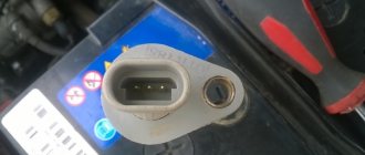
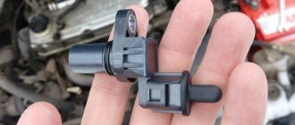
Removing the crankshaft position sensor
The sensor provides the controller with information about the rotation speed and angular position of the crankshaft.
The sensor is of the inductive type and reacts to the passage of the teeth of the drive disk, combined with the generator drive pulley, near its core.
The teeth are located on the disk at 6˚ intervals.
To synchronize with TDC of the pistons of cylinders 1 and 4, two teeth out of 60 are cut off, forming a cavity.
When a depression passes by the sensor, a so-called synchronization reference pulse is generated in it.
The installation gap between the core and the tops of the teeth should be within 1±0.4 mm.
When the master disk rotates, the magnetic flux in the magnetic circuit of the sensor changes - alternating current voltage pulses are induced in its winding.
Based on the number and frequency of these pulses, the controller calculates the phase and duration of the pulses to control the injectors and ignition coil.
Removing and checking the sensor
1. Turning off the ignition, disconnect the sensor connector.
2. Use a Phillips screwdriver to unscrew the sensor mounting screw.
3. Remove the sensor from the camshaft drive cover bracket
4. The resistance of a working sensor should be in the range of 550–750 Ohms
Install the sensor in reverse order.
Removing the coolant temperature sensor
The sensor is a negative temperature coefficient thermistor, meaning its resistance decreases as the temperature rises.
The controller supplies the sensor with a stabilized voltage of +5 V through a resistor (about 2 kOhm) and, based on the voltage drop across the sensor, calculates the coolant temperature, the values of which are used in most engine control functions.
If a malfunction occurs in the DTOZh circuits, the engine control system malfunction indicator lights up, the controller turns on the cooling system fan to constant operation and calculates the temperature value using a bypass algorithm.
We carry out the work on a cold engine.
Partially drain the coolant.
1. Turning off the ignition, disconnect the sensor connector.
2. Use a 19mm key to unscrew the sensor.
3. Remove the sensor along with the sealing ring
4. To check, lower the sensor into a vessel with coolant and heat the vessel.
We control the temperature with a thermometer. We measure the resistance of the sensor at different temperatures
Install the sensor in reverse order. The tightening torque of the sensor is 9–15 Nm. Add coolant to normal level.
Operating principle and functions of the device
The design and operating principle of the temperature meter have changed little since its first use on a car. Due to modern materials used in the manufacture of the sensor, it has decreased in size, and the accuracy of the readings has increased. The device is a thermal variable resistor enclosed inside a metal case with a threaded tip.
The following functions depend on the operation of the temperature sensor:
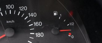
- Traditionally, the coolant temperature indicator operates from meter signals.
- Timely activation of forced engine cooling fans when the antifreeze reaches the set temperature threshold (about 100 °C).
- Enriching the air-fuel mixture and increasing idle speed on a cold engine.
- While driving, the controller collects readings from all sensors and, on this basis, forms the ratio of fuel and air in the mixture. The temperature meter is also involved in this process.
The design of a modern car may provide for the installation of several heating meters responsible for certain functions. Their location varies:
- on the upper pipe leading from the cylinder block to the radiator;
- in the thermostat housing;
- in the cylinder head;
- directly into the radiator.
It is not difficult to distinguish thermocouples from other types of sensors. All devices built into the engine cooling system and connected by wires to the controller are designed for temperature measurements. The only point: when you start looking for the location of the temperature meter for the purpose of checking, do not confuse the device with the knock sensor built directly into the cylinder block. When a machine has several thermal elements, their functions are usually distributed as follows:
- a meter built into the pipe is involved in preparing the fuel mixture for the engine;
- a device located in the radiator ensures that a cooling fan (or two) is turned on;
- The sensor in the cylinder head is responsible for the coolant temperature gauge.
Most low- and mid-price cars use one temperature sensor that performs all functions simultaneously. It is usually located on the thermostat housing or on the upper radiator hose.
Also interesting: Fuses and relays Lada 2121
Removing the throttle position sensor
The throttle position sensor is mounted on the throttle valve axis and is a potentiometric type resistor.
A stabilized voltage of +5 V is supplied to one end of its winding from the controller, and the other is connected to the ground of the controller.
The signal for the controller is removed from the third output of the potentiometer (slider).
By periodically measuring the output voltage of the TPS signal, the controller determines the current position of the throttle valve to calculate the ignition timing and the duration of fuel injection pulses, as well as to control the idle air control.
If the TPS or its circuits fail, the controller turns on the malfunction indicator and calculates the estimated value of the throttle position based on the crankshaft speed and air mass flow.
Removing and installing the sensor
1. Turning off the ignition, disconnect the electrical connector of the sensor
2. Using a Phillips screwdriver, unscrew the two screws securing the sensor to the throttle assembly
3. Remove the sensor.
We install the sensor on the throttle assembly in the reverse order.
In this case, the throttle valve must be in the closed position
Performance test
The most effective way to check is diagnostics using diagnostic equipment, in common parlance – a “car scanner”. This is the most accurate way to identify any car malfunctions, and there are 2 options - go to a service center or purchase a scanner for personal needs. At the moment, the second option will be the most preferable, because... will save you a lot of money in a short period of time. There are a very large number of diagnostic devices on the market for every taste and color.
If your budget is limited or you simply do not want to spend large sums on purchasing a device, then we can recommend you an adapter from the Korean manufacturer Scan Tool Pro Black Edition.
The adapter is compatible with 99% of cars manufactured in 1993 and connects via Bluetooth or Wi-Fi to any device on Android, iOS and Windows. It is noteworthy that, despite its low cost in the region of 2 - 2.5 thousand rubles. the device sees not only the engine, like most budget adapters, but also other components and assemblies of the car. It also shows the operation of all available sensors in your car in real time.
If you do not have such devices, and the nearest service is very far away, then there is another way to check, at home.
To check the thermal sensor, it will have to be removed from the car. To do this, follow these steps:
- Allow the engine to cool to 40-50 °C to avoid burning your hands during operation. Partially or completely drain the antifreeze from the cooling system.
- Disconnect the battery from the on-board power supply by removing the negative cable.
- Disconnect the block with wires from the thermoelement.
- Unscrew the part using a wrench of the appropriate size.
If the device is installed at the top point of the system, then it is not necessary to empty it entirely; it is enough to drain a third of the liquid into the container. All antifreeze must be drained when the thermocouple is located at the bottom of the radiator.
To carry out the tests you will need:
- a multimeter or other device capable of measuring circuit resistance;
- a small container for water (you can use a regular glass);
- thermometer with a scale up to 100 °C.
A thermometer is essential if you want to make accurate resistance measurements by referring to the reference chart for your vehicle. When there is no table, the serviceability of the part is checked without a thermometer according to its operating principle: the hotter the water in the glass, the lower the resistance at the contacts should be.
If the multimeter shows a certain resistance, then immerse the thermocouple in a glass of cold water and record the readings. Then add hot water and watch the resistance change, it should decrease. If there are no changes, purchase and install a new temperature sensor.
Also interesting: Where is the Chevrolet Niva starter relay located?
If the tests were successful and the device changes resistance when heating the water, then it is worth checking the connecting wires and cleaning the contacts. Little things like this often cause major problems.
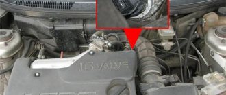
Removing the mass air flow sensor
The hot-wire mass air flow sensor (MAF) is located between the air filter and the air supply hose to the throttle assembly.
Depending on the air flow, the sensor output voltage varies from 1.0 to 5.0 V.
If the sensor fails, the controller calculates the mass air flow value based on the crankshaft speed and the location of the throttle valve.
The mass air flow sensor has a built-in air temperature sensor (ATS), the sensitive element of which is a thermistor installed in the air flow.
The output signal of the sensor varies in the range from 0 to 5.0 V, depending on the temperature of the air passing through the sensor.
If a malfunction occurs in the DTV circuit, the controller turns on the malfunction indicator and replaces the sensor reading with a fixed air temperature value (33˚C).
1. Turning off the ignition, disconnect the electrical connector of the sensor.
2. Using a Phillips screwdriver, loosen the clamp securing the supply hose
3. ...and remove it from the mass air flow sensor pipe.
4. Using a 10mm wrench, unscrew the two bolts securing the sensor to the air filter housing
5. Remove the mass air flow sensor
6. ...and sensor seal
Install the sensor in reverse order. The tightening torque of the bolts is 8–11 Nm.
Cost of sensors
Chevrolet Niva temperature sensors, although they are not consumables that require periodic replacement, still have a very low price. This is due to the simplicity of the design and the absence of the use of expensive materials or technologies in manufacturing. More detailed prices for meters are given in the table below.
Table - Cost of Chevrolet Niva temperature sensors
Also interesting: Chevrolet Niva camshaft sensor
| Sensor | Price |
| DUTOZH | 250-350 |
| DTOZH | 230-300 |
| Outdoor temperature sensor | 170-340 |
Removing the knock sensor
The knock sensor (DS) is mounted on the front upper part of the cylinder block.
The piezoceramic sensing element of the sensor generates an AC voltage signal, the amplitude and frequency of which corresponds to the vibration parameters of the engine.
When detonation occurs, the amplitude of vibrations of a certain frequency increases.
At the same time, to dampen detonation, the controller adjusts the ignition timing.
We remove the generator.
1. Turning off the ignition, disconnect the sensor connector.
2. Using a 13mm spanner, unscrew the bolt securing the sensor to the cylinder block
3. ...and remove the sensor. In photos 1–3, the exhaust pipe and air filter housing have been removed for clarity.
4. Before installing the sensor, clean the surface of its contact on the cylinder block
Install the sensor in reverse order. The tightening torque of the sensor mounting bolt is 20–25 Nm.
Removing the oxygen sensor
We carry out the work on an inspection ditch or a lift.
1. Disconnect the oxygen sensor connector.
2. Using the “22” key, unscrew the sensor
3. ...and take it out
4. When installing the sensor, do not allow grease or dirt to get on the slotted tip of the sensor and on the wiring harness connector.
We tighten the sensor with a torque of 30–45 Nm.