The camshaft position sensor (possible names - camshaft position sensor, phase sensor, Hall sensor) is an electronic device that monitors the technical characteristics of the engine, and is also part of the electronic engine management system.
It is designed to determine the angular position of the camshaft, in accordance with the position of the crankshaft. The information that comes from the DPRV is read by the electronic engine control unit to control fuel injection and ignition. As a rule, the DPRV is functionally connected to the crankshaft speed sensor, which is located on its pulley.
Area of application: modern injection gasoline or diesel internal combustion engines.
Kinds
Depending on the engine modification, the VAZ 2110 camshaft sensor has two types of design:
- Slotted. The sensitive element is U-shaped, and the moving element (mark) of the setting disk passes between its halves.
- Tortsevoy. It has the shape of a cylinder, at the end of which there is a sensitive element for reading the proximity of the mark.
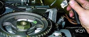
For each type of DPRV, the corresponding type of camshaft pulley is used. For a slotted DPRV, a pulley with teeth and one air gap along the entire circumference is used. When the gap passes, the sensor transmits a corresponding signal. For an end-mounted DPRV, a pulley with one mark or one tooth at the end of the pulley is used. The DPRV reacts when it passes a protruding pulley element.
DPRV on VAZ 2110 8 valves or 16 valves have no functional or design differences.
Articles
Instead of the numbers 2112-3706040, the article number 21120-3706040 is found. Both designations are correct. You can also find an article with the numbers -00, -01, -02... This is how the manufacturer is designated: 01 and 03 - “SOATE”, 00 - “Autoelectronics”, etc.
Read more: Renault Duster 3rd generation photo
Parts with article number 2112-3706040-04
Recently, flexible lead sensors have been launched. The length of the wires is 15 cm. So far there is nothing like this in retail. But the article numbers remained the same - 2112-3706040-XX.
Design
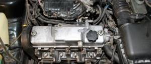
On the VAZ 2110, the camshaft position sensor is made in the form of a cylinder and has an end-mounted operating principle. Its structural elements are:
- plastic case;
- semiconductor wafer;
- secondary converter;
- magnet;
- current-carrying elements.
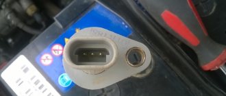
The DPRV connector has three contacts:
- constant power supply;
- transmission of the read signal to the control unit;
- weight.
Engines on which two camshafts are installed, and the gas distribution mechanism consists of sixteen valves, also have one camshaft position sensor of the same design.
Methods for checking the camshaft sensor
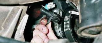
Before testing the sensor using a multimeter or other electronic tools, you must check its mechanical integrity. In particular, it is installed in a housing with an O-ring, ensuring its secure fastening. We need to check its condition. It would also be useful to check the integrity of the sensor body, whether there are cracks or other damage on it. It is advisable to check the drive disk to see if the teeth are damaged or if there are metal shavings on the sensor body or nearby.
On the Internet you can find information that supposedly the DPRV can be determined to work by simply checking its magnetic properties. In particular, bring a small metal part to its end (the working sensitive part), which should “stick” to the sensor. In fact, this is not the case , and a non-working DPRV may or may not have magnetic properties. Accordingly, verification must be performed using other methods.
There are two main ways to test the camshaft position sensor - using an electronic multimeter and using an oscilloscope. The first method is simpler and faster, but the second is more accurate and provides more diagnostic information.
Checking the camshaft sensor with a multimeter
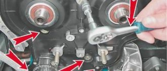
To check the DPRV, dismantling is necessary. This is not difficult to do; you just need to disconnect the contact group of wires from it and unscrew the fastening bolt. You will also need a small metal object (ferrous metal so that it is magnetic) to test.
Connection diagram for checking phase sensor 21110-3706040
Connection diagram for checking phase sensor 21120-3706040
The algorithm for checking the sensor with a multimeter is as follows:
- Take a multimeter and switch it to the DC voltage measurement mode in the range up to 20 V (depending on the specific multimeter model).
- Disconnect the “chip” from the sensor by unclipping the latch.
- Remove the sensor from its mounting location.
- On the “chip” of the sensor 21110-3706040 of a VAZ car (and on many others), contact “A” corresponds to ground, contact “C” is the positive wire, comes from the control relay, contact “B” is the signal wire (middle). For sensor chip 21120-3706040, contact “A” corresponds to ground, contact “B” is the positive wire from the control relay, contact “C” is the signal wire.
- Check the presence of power on the chips. To do this, you need to turn on the ignition on the car (but do not start the engine) and do this with a multimeter. If there is no power to the chips, then you need to look for the reason. This could be faulty wiring (insulation damage, broken wires), failure of the control relay, or a glitch in the electronic control system (ECU).
- Next, you need to connect the sensors for testing according to the diagrams shown in the figure.
- Apply a voltage of 13.5±0.5V to the sensor (although less is allowed, for example, 12...12.5 Volts from the battery).
- If, when power is applied to the sensor, the voltmeter detects a lack of voltage on the sensor, then this indicates either a breakdown of the sensor itself, the test can be completed and you can prepare to replace the sensor with a new one.
- Measure the voltage between the positive and signal contacts. It must be equal to at least 90% of the supply voltage (that is, if the supply voltage is 12 Volts, then the voltage at the signal contact must be at least 10.8 Volts).
- Bring a metal object prepared in advance to the end of the sensor (its signal part). Re-measure the voltage at the signal contact. It should be no more than 0.4 Volts. Remove the plate - the voltage value should be restored to 90.100% of the supply. If there are any deviations during the verification process, it means that the sensor has failed and must be replaced.
Checking the DPRV using an oscilloscope
An electronic oscilloscope helps to understand how the camshaft position sensor works and whether it produces pulses at all. Usually they use a so-called electronic oscilloscope, that is, simply a simulator program installed on a laptop or other similar device. You need to connect to the camshaft sensor and take an oscillogram from it. Ideally, there should be a smooth comb diagram with one drop-out peak that corresponds to the rapper passing through the sensor. If the oscillogram has a different shape, additional verification is needed.
When diagnosing the camshaft sensor of Nissan cars (in particular, Nissan Almera) with an oscilloscope, the shape of the oscillogram will be different. It will not be smooth, but in the form of 3 impulses, then a space, then 4 impulses - a space, 2 impulses - a space and one impulse - a space. For engines from this automaker, this feature is the norm.
Read more: Purpose of the crankshaft and timing belt
How does it work
The Hall effect is an increase in potential difference when a conductor is placed in a magnetic field.
The VAZ 2110 phase sensor also works according to this principle.
For normal operation of the DPRV, a DC supply is required.
When the camshaft pulley rotates, its mark (protrusion) aligns with the end part of the DPRV. When the mark is opposite it, this means the position of the camshaft at which the intake valve of the first cylinder is open.
In this case, the potential difference in the semiconductor wafer DPRV increases. This signal passes through a secondary converter, which generates and sends a pulse to the electronic control unit. The secondary converter is built into the DPRV design.
Malfunctions
The primary signs of a DPRV malfunction include unstable engine operation, poor starting, poor dynamics, loss of power and random engine stopping, and the Check Engine light coming on.
However, these symptoms may indicate a breakdown of any electronic element of the engine.
To identify specific malfunctions of the camshaft position sensor, you must perform the following steps:
- visual inspection for the integrity of the device and its wiring;
- checking the device connector. The connector is susceptible to wear or contamination;
- checking the electrical wiring of the device using a voltmeter for electrical conductivity (allows you to find the faulty wire);
- checking the device with a voltmeter for appropriate resistance;
- computer diagnostics of the engine control unit and decoding of detected error codes.
Phase sensor VAZ 2112
The phase sensor (PPV) is one of the most critical elements that ensures optimal operation of the internal combustion engine. Its main purpose is to analyze the angular position of the camshaft in a certain time period. The information received from it is needed for the operation of the ignition and fuel injection mechanisms. Having this data, the car ensures coordinated operation of the camshaft, taking into account the placement of the cylinders in the engine, which allows the supply of gasoline to a specific cylinder and ignition of the fuel-air mixture.
Symptoms of a problem
If you have the following symptoms, then the phase sensor (df) is most likely faulty.
When starting the engine, the starter spins for 3-4 seconds, then the engine starts and the check engine lights up. In this case, during startup, the computer waits for readings from the phase sensor, does not wait and switches to engine operating mode relying on the ignition system (according to DPKV).
Repair
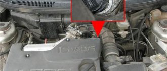
Before checking the DPRV or before starting any independent actions, you need to familiarize yourself with the connection diagram for the VAZ 2110 camshaft sensor, as well as the features of its installation in the engine body.
The type of action performed depends on what signs of malfunction have been identified:
- if there is visible mechanical damage to the wiring or exposure of live parts, it must be replaced, but repairs in the form of re-insulation of the wires are also possible;
- If the sensor is mechanically damaged, it must be replaced. It is not recommended to repair or disassemble it;
- if the connector is dirty, it is necessary to reconnect with a visual inspection and cleaning of the electrical contacts;
- Wear of the connection connector requires its maintenance or replacement of the sensor. Maintenance consists of ensuring a tight fit of the connected parts;
- When checking the electrical wiring or sensor with a voltmeter and identifying deviations, it is necessary to replace the faulty element. When connecting the voltmeter probes to the electrical power contacts, the sensor resistance should not be lower than 550 Ohms or higher than 750 Ohms;
- If an internal malfunction of the sensor is detected during computer diagnostics, it must be replaced.
Replacing the DPRV is carried out by disconnecting it, dismantling the faulty one, installing a new one and reconnecting the power connector.
It is important to note that after performing any actions aimed at eliminating identified faults, it is necessary to recheck the engine operation.
The operating manual does not recommend disabling the sensor yourself and further operating the vehicle.