Purpose and principle of operation of the ABS sensor
Anti-lock braking systems appeared on cars in the 70s, significantly increasing their safety during emergency braking. ABS consists of a control unit, a hydraulic unit, wheel brakes and speed sensors. The main device of the system is the control unit, into which sensor signals are received and processed. The data is analyzed and a decision is made to slow down or accelerate the wheels in the form of a signal to the valves of the hydraulic unit, which acts as a control.
When you press the brake pedal hard, the sensor detects that the wheel is locked and sends a signal to reduce the braking force, after which the brake fluid pressure drops and the wheel unlocks. If the brake pads are not released, the process will be repeated until the desired result is achieved. Thus, the operation of ABS is a cycle: braking - analysis - braking. The sensor itself controls the speed of rotation of the wheel.
The system is activated instantly, even before the wheel locks, which is indicated by the receipt of a signal on the instrument panel and is felt by characteristic shocks in the brake pedal. If a breakdown occurs, the brake system remains operational and operates normally.
Basic elements of ABS
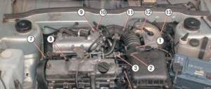
When starting to diagnose ABS yourself, you need to understand what elements the entire system consists of. Its main elements include:
- Control block;
- hydraulic block;
- wheel braking mechanisms;
- sensors that measure wheel speed.
In addition, there are a large number of connecting wires, which also need periodic checking, especially if the ABS lamp on the panel comes on frequently.
Control block
The main part of the system, which receives signals from all sensors, analyzes them, and issues control commands to the hydraulic unit. This unit is also used by other driver assistance systems, for example, the exchange rate stability system. Problems with the central unit occur quite rarely, since it is well protected from the negative effects of the environment. But it is worth noting that the unit is very sensitive to voltage changes, and if the battery is insufficiently charged, it can turn off completely.
Hydraulic block
Includes brake master cylinder, solenoid valves and hydraulic accumulator. Based on a signal from the central unit, which has recognized the wheel locking, the magnetic valve opens, and the excess brake fluid immediately goes into a special reservoir - a hydraulic accumulator, which leads to a drop in pressure in the system and does not allow the wheels to lock completely, even if the brake pedal is pressed all the way.
Induction sensors
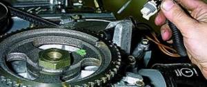
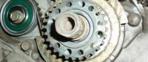
They are the ones who do the dirtiest, but most important work, allowing you to constantly monitor the speed of rotation of all wheels. Such sensors are installed on each hub. In essence, they are ordinary induction coils working in tandem with a gear wheel. Signals from the sensors enter the central unit, where they are analyzed. The sensors have to work in the most difficult conditions, so if problems arise in the operation of the ABS, it is advisable to start checking with them.
Signs of a malfunctioning ABS sensor
The first sign of an ABS malfunction is a lit indicator on the instrument panel that does not go out for more than 6 seconds after turning on the ignition, or does not turn on when driving. A system breakdown is detected when the vehicle is moving at a speed of more than 25 km/h. There are quite a few problems that can happen with the anti-lock braking system, but the most common ones include the following:
- ABS sensor wire is broken or the controller unit is damaged. In this case, an error is displayed on the instrument panel, the system is turned off, and signals about changes in angular velocities are not given.
- The wheel sensor of the system has failed. When turned on, the system performs self-diagnosis and detects an error, but continues to function. The cause of the breakdown may be oxidation of the contacts, poor power supply to the sensor and a short circuit to ground.
- Receipt from an additional device of information about different angular speeds of wheels at different tire pressures or different tread patterns, when the wheels brake differently.
- Mechanical failure of elements - hub bearings, play and fracture of the rotor on the wheel sensor. In case of such failures, the system does not start. This also includes ABS pump failure.
The most vulnerable element of the system is the wheel sensor, which is located next to the rotating hub and axle shaft. Exposure to dirt and play in the hub bearings can damage the device, completely blocking the operation of the ABS. Along with the indicator signal on the instrument panel, the following signs indicate a sensor failure:
- The on-board computer displays an ABS system error code.
- There is no characteristic vibration or sound when pressing the brake pedal.
- The wheels lock during emergency braking.
- Appearance of the parking brake signal when it is disabled.
Causes and symptoms of malfunctions
In new generation cars, when the ignition is turned on, automatic self-diagnosis of the anti-lock braking system occurs, during which the performance of all its elements is assessed.
Self-diagnosis shows an error. ABS is disabled.
Incorrect operation of the control unit.
Broken wire from the sensor to the control unit.
Diagnostics does not detect errors. ABS is disabled.
Violation of the integrity of the wiring from the control unit to the sensor (break, short circuit, oxidation).
Self-diagnosis gives an error. ABS works without turning off.
Broken wire of one of the sensors.
ABS does not turn on.
Break in the power supply wire of the control unit.
Chips and fractures of the impulse ring.
Checking the ABS sensor
If the ABS sensor malfunctions, the control unit stops receiving commands and the system stops working, which is determined by the wheels locking when braking. Possible malfunctions of the device are determined by the tester. To do this, you need the tester itself, a soldering iron and pins for repairs. The pins are connected to the connectors, and the device measures the resistance of the ABS sensor, which must correspond to the parameters specified in the operating manual.
If there is no resistance, then there is a short circuit in the circuit; if it tends to infinity, then there is an open circuit in the circuit. Full diagnostics of the sensor is carried out by ringing all its wiring, since one of the reasons for malfunctions is a violation of the integrity of the wires. A working device has the following indicators:
- Insulation resistance – more than 20 kOhm.
- Leg – front right ABS sensor, resistance from 7 to 25 kOhm.
- Leg – rear right ABS sensor, resistance from 6 to 24 kOhm.
The sensors can also be checked in voltmeter mode. Each sensor is tested in turn using the following algorithm:
- After jacking up the required wheel, connect the connectors of the PIN cable to the tester.
- The wheel rotates at a frequency of 1 rpm.
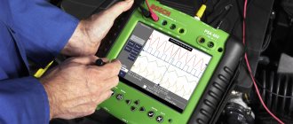
A working sensor should give readings within 0.25-1.2 V. Increasing the wheel speed should increase the voltage reading. More informative information when testing the sensor can be obtained using an oscilloscope, but the device is quite expensive and requires special knowledge and conditions for maintenance.
Checking the sensor resistance
Before starting the testing procedure, it is advisable to know the standard resistance value of the ABS sensors installed in your car. This information can be found either on the manufacturer's website or on the Internet. The algorithm for checking the sensor resistance is quite simple:
- We hang the wheel using a jack and remove it.
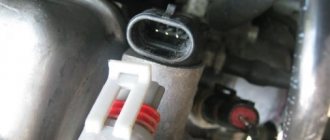
- We find the ABS sensor and disconnect its connector from the wiring leading to the control unit.
- We switch the multimeter to resistance measurement mode.
- We connect the probes to the contacts of the sensor connector and look at the readings of the device.
- If the ohmmeter shows “0”, this means that there is an open circuit in the sensor coil. This sensor must be replaced. Device readings that exceed the nominal value by 2–3 times also indicate a malfunction of the sensor, namely that its coil is “burnt” and the signals coming from it to the control unit are incorrect.
Advice! Typically, the resistance of passive induction sensors is in the range of 700÷2500 Ohms. If you are unable to find technical information about specific sensors installed in the car, you will have to check the resistance of all ABS sensors. Their simultaneous failure is unlikely. By comparing the results of all measurements taken, it will be possible to draw a conclusion about which specific sensor is “buggy” and replace only that one.
You can check the resistance of all sensors without removing the wheels. For this:
- We find the ABS control unit under the hood of the car.
- We disconnect from it the connector in which the wires from the sensors and other devices included in the anti-lock brake system are fixed.
- Next, we connect the multimeter probes to the corresponding contacts (to which the sensors are directly connected) and sequentially check the resistance of all sensors. The pinout of the connector can be found in the operating instructions or on the manufacturer's website.
On a note! This test method allows you to determine not only the resistance of the sensor coil, but also the serviceability of the wiring from the sensor itself to the control unit.
ABS sensor repair
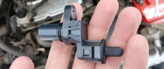
If a faulty ABS sensor is detected, it is dismantled, after which the issue of replacement or repair is decided. The cost of the device is quite high, and often there is a long wait for its delivery, which makes repairs quite feasible. The work is performed in the following order:
1. The sensor is disassembled by cutting off the part in which the measuring coil is located with a hacksaw. The body is carefully filed in a circle so as not to damage the fasteners.
2. The plastic casing protecting the coil is removed using a sharp knife and the winding is unwinded from the frame.
3. Wind a new coil with a wire of the same diameter. The RES-8 relay winding is suitable for this. The number of windings must provide the required resistance value - 0.92-1.22 kOhm. The work is carried out very carefully, since the wire is quite thin, and if it breaks, the process begins again.
4. The ends of the wires are soldered to the terminals, and the coil is effectively insulated from moisture using silicone or wax sealant.
5. The sensor is assembled by restoring the old housing. If the shell is critically damaged, it is made independently from the body of an electrolytic capacitor, suitable in size, and epoxy glue. A hole is made at the bottom of the body for the coil rod. After placing the updated part there, glue is poured.
6. After the glue has dried, the capacitor shell is removed, and the sensor mount is glued to its original place.
7. After the repair is completed, the sensor body is ground with sandpaper to accurately fit the socket. During the installation process, observe the following rules:
- The core of the device is placed parallel to the teeth of the response disk and is controlled so that it does not overlap a pair of adjacent teeth;
- A gap of 0.9-1.1 mm is left between the tooth and the core.
At the end of the installation, check the functionality of the system by starting the engine and making sure that the ABS indicator goes out 6 seconds after the start.
Using a laptop as an oscilloscope
From a technical point of view, professionals consider using an oscilloscope to be the most correct method for checking ABS sensors. However, the device is expensive, and it makes no sense to purchase it just to test sensors. Well, if you have a laptop, then using it as an oscilloscope is quite simple. First, we make a measuring cord to connect the sensor connector to the microphone input. To do this, you will need a 3.5 mm mini jack plug, two resistors and a couple of pieces of wire of a suitable length. The cash costs for purchasing the necessary components will not exceed 50 rubles. We solder the wires to the contacts of the mini-jack, and install a resistive divider in the gap (to protect the sound card) according to the diagram below.
Then everything is simple:
- We install a special Oscilloscope program on the laptop (for example, Winscope or Avangard).
- We connect the wires to the ABS sensor connector, and the plug to the microphone input.
- Rotate the wheel hub.
- If the sensor is working properly, we see a clear sinusoidal signal on the screen.
On a note! If you don't have an assistant, it will be very difficult to rotate the wheel and watch the laptop screen at the same time. For convenience, we recommend using the recording function. By turning on the playback mode (after performing the test described above), you will be able to see the test results.
The presence of ABS in a vehicle greatly increases traffic safety. Gradually, car parts wear out and may become unusable. Knowing how to check the ABS sensor, the driver can identify and fix the fault in a timely manner without resorting to the services of a workshop specialist.
Replacing the ABS sensor
The procedure for replacing the sensor is quite simple, and it is not too expensive at a specialized service station. Replacing the device yourself is also quite possible. To do this, after purchasing a quality part, perform the following steps:
- Using a jack, lift the corresponding wheel to provide access to the sensor.
- Determine the location of the device and the method of its dismantling.
- Unscrew the bolt holding the device in working position.
- The sensor is removed and visually inspected for damage.
- Install a new sensor.
- All electrical connections are connected correctly.
- Secure the device with the previously unscrewed bolt.
- After installation is complete, you need to drive the car and test the operation of the system.