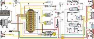
Connection diagram
The process of diagnosing an ECU using a special scanner.
Electronic control units of the VAZ-2110 are the main tool for controlling and automating most processes in the car. To adjust the software, they often resort to replacing the “brains” with more “flexible” ones and reflashing the ECU.
First of all, it is necessary to clarify several terms that will be required when considering questions about changing the electronic control unit:
- Wiring compatibility . To replace it, the connectors on the old ECU and the new one will need to match.
- Software is a predetermined algorithm that can change depending on the needs or desires of the motorist.
- The hardware component is the electronic control unit itself, boards or other components that allow the systems associated with the ECU to function normally.
For the VAZ-2110 family there were two types of connectors. So, for the “brains” January 5.1.x, Bosch M1.5.4, Bosch MP7.0, and VS 5.1 there was a 51-pin connector, but for January 7.2(+), Bosch M7.9.7(+) and M73 - 81 -pin.
That is, the interchangeability of control units is caused by the pinout of the unit.
ECU January 7.2.
Differences
Fundamental differences between 81-pin blocks and blocks of previous generations:
- Overall body dimensions and weight have been reduced.
- New, more modern connectors with improved connection reliability.
- The controllers have built-in switches, therefore, instead of ignition modules, ignition coils can be used, which increase the reliability of the ECM as a whole.
- There is no software or hardware compatibility with any of the previously released units.
Even electronic control units from the same manufacturer will differ significantly in pinout. Therefore, the interchangeability of the “brains” will depend on the number of connector pins. Also, it is worth understanding that the firmware will play a big role. When changing the ECU, the motorist will have to reflash the unit for the correct operation of all vehicle devices.
ECU January 5.1.
A very important nuance remains that the software of the control unit must be compatible and comply with the type of injection, as well as the toxic standards laid down by the manufacturer.
Assignment of contacts of ECU Bosch M1.5.4, MP7.0 and January-5.1
Pinout of 55-pin ECU.
Let's look at the pinout of control units with 55-pin “brains”:
| Bosch M1.5.4 (1411020 and 1411020-70) January 5.1.1 (71) | Bosch M1.5.4 (40/60) January-5.1 (41/61) January 5.1.2 (71) | Bosch MP7.0 | |
| 1 | Ignition 1-4 cylinders. | Ignition 1-4 cylinders. | Ignition 1-4 cylinders. |
| 2 | . | Ground ignition wire. | . |
| 3 | Fuel pump relay | Fuel pump relay | Fuel pump relay |
| 4 | Stepper motor PXX(A) | Stepper motor PXX(A) | Stepper motor PXX(A) |
| 5 | Canister purge valve. | Canister purge valve. | |
| 6 | Cooling fan relay | Cooling fan relay | Left fan relay (only on Nivas) |
| 7 | Air flow sensor input signal | Air flow sensor input signal | Air flow sensor input signal |
| 8 | . | Phase sensor input signal | Phase sensor input signal |
| 9 | Speed sensor | Speed sensor | Speed sensor |
| 10 | . | General. Oxygen sensor weight | Oxygen sensor weight |
| 11 | Knock sensor | Knock sensor | Knock sensor input 1 |
| 12 | Power supply for sensors. +5 | Power supply for sensors. +5 | Power supply for sensors. +5 |
| 13 | L-line | L-line | L-line |
| 14 | Weight of injectors | Weight of injectors | Weight of injectors. Power "ground" |
| 15 | Control of injectors 1-4 | Oxygen sensor heater | Check Engine Light |
| 16 | . | Injector 2 | Injector 3 |
| 17 | . | Recirculation valve | Injector 1 |
| 18 | Power supply +12V non-switchable | Power supply +12V non-switchable | Power supply +12V non-switchable |
| 19 | Common wire. Weight of electronics | Common wire. Weight of electronics | Common wire. Weight of electronics |
| 20 | Ignition 2-3 cylinders | Ignition 2-3 cylinders | |
| 21 | Stepper motor PXX© | Stepper motor PXX© | Ignition 2-3 cylinders |
| 22 | Check Engine Light | Check Engine Light | Stepper motor PXX(B) |
| 23 | . | Injector 1 | Air conditioner relay |
| 24 | Stepper motor weight | Weight of stepper motor output stages | Power grounding |
| 25 | Air conditioner relay | Air conditioner relay | . |
| 26 | Stepper motor PXX(B) | Stepper motor PXX(B) | Weight of sensors TPS, DTOZH, DMR |
| 27 | Ignition switch terminal 15 | Ignition switch terminal 15 | Ignition switch terminal 15 |
| 28 | . | Oxygen sensor input | Oxygen sensor input |
| 29 | Stepper motor PXX(D) | Stepper motor PXX(D) | Oxygen sensor 2 input signal |
| 30 | Weight of sensors MAF, DTOZH, DPS, DD, DPKV | Weight of sensors MAF, DTOZH, DPS, DD, DPKV | Knock sensor input 2 |
| 31 | . | Reserve output high current | Rough road sensor input signal |
| 32 | . | . | Fuel consumption signal |
| 33 | Control of injectors 2-3 | Oxygen sensor heater. | . |
| 34 | . | Injector 4 | Injector 4 |
| 35 | . | Injector 3 | Injector 2 |
| 36 | . | Exit. Intake pipe length control valve. | Main relay |
| 37 | Nutrition. +12V after the main relay | Nutrition. +12V after the main relay | Nutrition. +12V after the main relay |
| 38 | . | Low-current backup output | . |
| 39 | . | . | Stepper motor РХХ © |
| 40 | . | Reserve input discrete high | . |
| 41 | Request to turn on the air conditioner | Request to turn on the air conditioner | Oxygen sensor heater 2 |
| 42 | . | Reserve input discrete low | . |
| 43 | Signal to tachometer | Signal to tachometer | Signal to tachometer |
| 44 | CO - potentiometer | Air temperature sensor | . |
| 45 | Coolant temperature sensor | Coolant temperature sensor | Coolant temperature sensor |
| 46 | Main relay | Main relay | Cooling fan relay |
| 47 | Programming permission | Programming permission | Air conditioner request signal input |
| 48 | Crankshaft position sensor. Low level | Crankshaft position sensor. Low level | Crankshaft position sensor. Low level |
| 49 | Crankshaft position sensor.High level | Crankshaft position sensor.High level | Crankshaft position sensor.High level |
| 50 | . | Recirculation valve position sensor | Programming permission |
| 51 | . | Request to turn on the power steering | DC heater |
| 52 | . | Reserve input discrete low | . |
| 53 | Throttle position sensor | Throttle position sensor | Throttle position sensor |
| 54 | Fuel consumption signal | Fuel consumption signal | Stepper motor IAC (D) |
| 55 | K-line | K-line | K-line |
Description of contacts ECU M7.9.7 / January 7.2
Let's look at the pinout of control units with 81-pin “brains”:
| № | Compound |
| 1 | 21114 - Not used / 21124 - Ignition coil 2 cylinders. |
| 2 | 21114 - Ignition 2-3. Control of the primary winding of the ignition coil, act. level is low. / 21124 — Ignition coil 3 cylinders. |
| 3 | Ignition circuit weight |
| 4 | 21114 - Not used / 21124 - Ignition coil 4 cylinders. |
| 5 | 21114 - Ignition 1-4. Control of the primary winding of the ignition coil, act. level is low. / 21124 - Ignition coil of cylinder 1. |
| 6 | Injector 2. Active level low |
| 7 | Injector 3. Active level low |
| 8 | Output to tachometer. |
| 9 | Not used |
| 10 | Fuel consumption signal |
| 11 | Not used |
| 12 | Battery, terminal 30 of the ignition switch. |
| 13 | Nutrition. Ignition switch terminal 15 |
| 14 | Main relay |
| 15 | Contact "A" DPKV |
| 16 | TPDZ |
| 17 | TPS mass / TPS mass, DND |
| 18 | Input - oxygen sensor |
| 19 | Input - knock sensor |
| 20 | Knock sensor weight |
| 21 | Not used |
| 22 | Not used |
| 23 | Not used |
| 24 | Not used |
| 25 | Bosch Only - High Current Output, Reserved |
| 26 | Bosch Only - High Current Output, Reserved |
| 27 | Injector 1. Active level low |
| 28 | Not used / DK2 heater control output |
| 29 | Not used / Engine cooling fan control output 2 |
| 30 | Not used |
| 31 | CE lamp, act. level low |
| 32 | Power supply TPDZ / Power supply TPDZ, DND |
| 33 | Power supply for mass air flow sensor |
| 34 | DPKV input, contact “B” |
| 35 | Weight of DTOZH / Weight of DTOZH, mass air flow sensor, 1 DC (UDK), 2 DC (DDK) |
| 36 | Mass of the mass air flow sensor |
| 37 | Signal input from mass air flow sensor |
| 38 | Not used |
| 39 | Signal input from DTOZH |
| 40 | Signal input from intake air temperature sensor |
| 41 | Not used |
| 42 | Not used / DND signal input |
| 43 | Not used |
| 44 | On-board voltage input at the main relay output |
| 45 | Phase sensor power output |
| 46 | Canister purge valve control output |
| 47 | Injector 4. Active level low |
| 48 | Oxygen sensor heater control output |
| 49 | Not used |
| 50 | Additional starter relay control output |
| 51 | Controller weight |
| 52 | Not used |
| 53 | Controller weight |
| 54 | Not used |
| 55 | Not used / Signal input DK2 (DDK) |
| 56 | Not used |
| 57 | Input for encoding calibration data options. The controller memory can contain 2 sets of calibration data; switching is performed by shorting to ground. |
| 58 | Not used |
| 59 | Speed sensor |
| 60 | Not used |
| 61 | Weight of output stages |
| 62 | Not used |
| 63 | On-board voltage input at the main relay output |
| 64 | Output “D” IAC |
| 65 | Output “C” IAC |
| 66 | Output “B” IAC |
| 67 | Output “A” IAC |
| 68 | Engine cooling fan relay control output, act. level - low |
| 69 | Air conditioner relay control output, act. level - low |
| 70 | Fuel pump relay control output, act. level - low |
| 71 | K-Line |
| 72 | Not used |
| 73 | Not used |
| 74 | Not used |
| 75 | Input request to turn on the air conditioner, act. level - high |
| 76 | Power steering request input, act. level - high |
| 77 | Not used |
| 78 | Not used |
| 79 | Phase sensor signal input |
| 80 | Weight of output stages |
| 81 | Not used |
instruction manual on how to connect and configure the BC
The VAZ-2110 on-board computer is used to control vehicle systems. In its original configuration, the car leaves the factory without a smart gadget, but this does not prevent the driver from purchasing it. Before this, it is necessary to evaluate the technical characteristics of the models on the market. Each of them is designed for specific operating conditions of the VAZ-2111, 10 or 12.
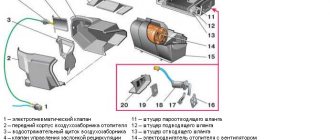
Functional purpose of the device
The development of the technical component of vehicles has led to an abundance of electronic and mechanical devices that control the operation of the car.
Each of them reflects one or another indicator, which a person does not always have time to analyze. This is where the VAZ on-board computer will help, taking control of what is happening. In addition to monitoring the operation of vehicle systems, it will promptly inform the owner about a failure.
Another advantage is that the standard on-board computer analyzes the technical condition of the car within the specified parameters. In practice, this means that the driver can ask a question regarding the presence of components or assemblies whose performance exceeds the technical norm. Preventative analysis reduces the likelihood of downtime due to technical failure. The VAZ trip computer differs in the available options depending on the configuration:
- Carburetor is a budget option that does not have sufficiently wide functionality. Installation does not take much time, and operation is simple. It is difficult to find it on the market due to low demand among VAZ-2110 owners.
- Injection - there are various options on the market that take into account the needs of drivers. Among the main advantages is the ability to conduct in-depth diagnostics. For example, if the car does not start because the injector has failed, the system will notify you in advance. The cost of the on-board computer depends on the configuration.
- Universal - installation is carried out on a VAZ-2111, 10 or 12 without taking into account technical specifications. Installation is carried out behind the rear view mirror or windshield.
- Adapted - selected taking into account the make and model of the vehicle. Installation is carried out in a strictly designated place, which the instructions will help you find.
Installation recommendations
The efficiency of the device is determined at the stage of selection and subsequent installation. An on-board computer (BC) is selected for the VAZ-2112, which collects and analyzes incoming information. Regardless of the model, it is equipped with a Check Engine light. When it is triggered, the bookmaker will independently determine that it is not working.
Experienced drivers do not advise overpaying for sensors of humidity and outdoor temperature levels, a chronometer, and an alarm clock. These indicators are easy to obtain using a standard VAZ-2110 thermometer. Once the driver has made his choice, installation can begin. First, you should study the passport supplied with the device, which will tell you how to connect the on-board computer.
When operating a vehicle, only 1 BC is required. The presence of a second computer in most cases provokes failures in the operation of both systems. Connection to the VAZ-2112 is carried out via a 9-pin block. It is located behind the BC and has a trapezoidal shape.
A diagram of the vehicle and the on-board computer itself will help you connect the contacts correctly. To connect to the VAZ-2110 in the standard BC, contacts No. 10 and No. 11 are not used. They are intended for temperature, humidity and pressure sensors. The installation of the BC is completed by connecting the K-line. Mistakes cannot be made, otherwise the indicators obtained from the VAZ-2112 will be inaccurate.
The connecting line runs in the diagnostic block provided for it. When checking valves and other preventive inspections at a service station, it is into the block that the technician looks into the block to connect the equipment. When laying the cable, you should make sure that there are no bends and that it is close to moving elements. For example, when operating a vehicle, the K-line can be damaged by the gas pedal.
Troubleshooting BC
Malfunctions occur with BCs of various modifications. It would be useful for the owner to know what to do in such cases. Many failures occur when the on-board computer was not installed properly. First, you need to check the reliability of the connections. Secondly, there is a high probability of accidental damage or pinching of the K-line. Multitronics itself will report this, displaying obviously incorrect data.
You can deal with the problem yourself. If it is connected to a damaged K-line, then you need to purchase a new wire for the VAZ-2111 at a car store or on the market.
It is inexpensive, and the entire replacement procedure will take no more than 60 minutes. More time will be required if the problems of the on-board computer 2110 are caused by broken contacts. It is necessary to disconnect the device after performing a visual inspection. If bent plugs are still present, you should select new ones from the store and resolder them.
Using the BC on a VAZ passenger car allows the owner to always be aware of the technical condition of the car. The device is selected based on needs. Its effectiveness depends on correct installation.
korchim.ru
Choice of "Brains"
AvtoVAZ Lada 2110 cars have been equipped with several electronic control units throughout their production history. Thus, the following ECUs can be found on vehicles:
- January 4 - the cost of such an electronic control unit is 4,000 rubles.
- Bosch M1.5.4 - the average price will be 5,500 rubles.
- January 5.1 - the market price will be about 6,000 rubles.
- VS 5.1 - cost 5,000 rubles.
- Bosch MP7.0 - the cost of the control unit will be around 6,000 rubles.
- Bosch M7.9.7 is a little more expensive than its brother, the price ranges from 6000-6500 rubles.
- January 7.2 and January 7.2+ - these blocks will cost the car owner 5000-5500 rubles.
According to the experience of motorists and the recommendations of specialists, it is best to take electronic control units marked Bosch MP7.0, January 7.2+ and January 5.1.
If you have to change the remaining blocks, it is recommended to take an ECU with these markings, since they are more “flexible” for changing the software.
How to remove the VAZ on-board computer with your own hands?
Nowadays, most automakers equip their cars with such a device as a standard on-board computer. This unit allows the car owner to monitor the quality of operation of various systems of his “iron horse” in real time. However, not every driver wants to see such innovative technologies on board their vehicle. In particular, not all motorists driving VAZ cars on our roads are happy with this gadget, simply imposed by AvtoVAZ. However, if you wish, you can remove the VAZ on-board computer yourself. Yes, that’s right: you don’t need to visit a car service center for this. The driver can easily remove the on-board computer with his own hands, spending a little personal time.
Instructions:
1. First of all, you need to carefully study the vehicle’s operating manual. The manual probably contains not only information on using the standard on-board computer, but also detailed instructions on how to dismantle it. If for some reason such instructions are not there, you can ask for clarification on a specialized forum dedicated specifically to your VAZ car model. In addition, on the forum you will be able to find a lot of information and reviews from motorists themselves, who already have experience in similar work on removing the on-board computer.
2. It would be a good idea to get advice about the warranty from an employee of the dealership where you purchased the car. The fact is that some car dealerships may deprive their client of a warranty if he removes any pre-installed equipment during the warranty period.
3. Important: on tenth generation VAZ and Priora cars, before dismantling the computer, it is necessary to remove the radio. Follow safety precautions and be sure to remove the negative terminal from the battery before dismantling the radio. You will de-energize the entire on-board power system, which means that the possibility of a short circuit will be completely excluded.
4. Next, simply press the open button and remove the outer panel of the radio. After this, find four holes on the end of the radio. Insert special keys into these holes and press them all the way.
5. Gently pull the radio casing towards you and remove this unit. From the rear side, carefully disconnect all the wire connectors. Next, stick your hand into the hole where the radio was previously located, try to feel the fastenings on the back of the computer block. These fasteners must be very carefully opened, after which you should press the body of the gadget itself.
6. Now you can remove the standard on-board computer from the groove in which it was previously installed. Don't forget to disconnect all wires connected to the device from the back. If you do not plan to install a new on-board gadget after this, all wiring for connecting the computer should be connected with a plastic bundle, and the hole itself should be closed with a regular plastic plug.
autoremka.ru
On-board computer diagnostics
Faulty sensors can be determined using ECU diagnostics.
To identify faults in the electronic control units of the VAZ-2110, diagnostic equipment is used. Usually they use a tablet or laptop with special software. Also, the motorist, if the operation is performed independently, will need a special OBD II cable.
The process of diagnosing an ECU using a laptop.
Diagnostics are carried out to determine errors in the electronic control unit and troubleshoot problems in on-board systems, especially on engines. After identifying the error, it is necessary to decipher and find the cause of the malfunction in order to eliminate it.
Algorithm for performing self-installation of an on-board computer
So:
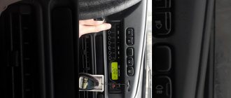
- first you need to free the central dashboard of the car from the plug;
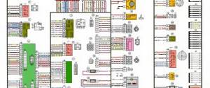
Connection block for on-board computer VAZ 2110
- after which, on the central dashboard you will need to find a diagnostic block of 9 contact wires;
- A 9-pin block is found on all VAZ “tens”;
- then, you need to connect the car’s on-board computer to the block.
Note. You must remember to draw the so-called K line.
Algorithm for drawing line K
So:
- It is imperative to use a pre-prepared meter wire in order to establish the appropriate connections;
Brake pads for VAZ 2110 included
- the prepared wire must be inserted into the block, and specifically into the second contact;
- the other end of the pre-prepared wire must be connected to the diagnostic block, having first pulled it under the dashboard.
Note. In order to easily install the wire, you need to temporarily turn the right side of the dashboard to one side.
- after the corresponding wire reaches the diagnostic block, it will need to be connected to the “M” socket;
- Now you can connect the on-board computer with complete confidence by installing it in the appropriate place;
- The final step is to conduct a full check of the functionality of the on-board computer.
Note. Before you begin installing any car computer, you should read the attached recommendations. Since there are many completely different models of car on-board computers, some of them require certain installation specifics.
On-board computer options
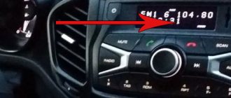
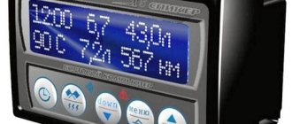
On-board computer STATE X1M-station wagon.
Regular BC.
BK-40.
BK-10.