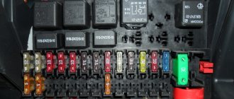
Fuse diagram
Its principles have not changed significantly since the advent of the B2 generation in 1987. An explanation of the circuit translated into Russian is presented in the table below, as well as a list of relays and the order of their arrangement, which can be used as a printout if necessary.
| Fuse | Power, A | What protects |
| 1 | 15 | Fog lights, rear fog lights |
| 2 | 15 | Emergency crew |
| 3 | 30 | Horn, heated seats |
| 4 | 15 | Electronic clock, trunk light, interior light, vanity mirror, reading light, cigarette lighter, trip computer, automatic air conditioning, radio, self-diagnosis system |
| 5 | 30 | Radiator fan speed 2 |
| 6 | 5 | Rear right dimensions |
| 7 | 5 | Rear left dimensions |
| 8 | 10 | Right high beam headlight, high beam warning light |
| 9 | 10 | Far left headlight |
| 10 | 10 | Right low headlight, electric motor for adjusting the right headlight position |
| 11 | 10 | Left low beam headlight, left headlight adjustment motor |
| 12 | 15 | Instrument panel, reversing lights, control system, automatic transmission, differential lock, on-board computer, speed control, retarder relay, interior lighting, electronic thermal switch, relay for turning on the radiator fan |
| 13 | 15 | Gasoline pump |
| 14 | 5 | License plate light, instrument panel light, engine compartment light, glove compartment light, automatic air conditioning |
| 15 | 25 | Turn signals, windshield wiper, windshield washer pump, heated windshield washer nozzles, radiator fan relay, air conditioning |
| 16 | 30 | Heated rear window, heated mirrors |
| 17 | 30 | Interior fan, automatic air conditioning |
| 18 | 5 | Electric mirrors |
| 18 | 15 | Rear window wiper (Avant) |
| 19 | 10 | Central locking, heated lock switch cylinder, anti-theft system |
| 20 | 30 | Radiator fan, 1st cabin fan speed |
| 21 | 10 | Diagnostic connector |
| 22 | — | Not used (cars with gasoline engines) |
| 22 | 80 | Glow plugs (cars with diesel engines) |
| 23 | — | Not used |
| 24 | — | Not used |
| 25 | 5 | Lambda probe heating. For cars with diesel engines – not used |
| 26 | 30 | Trailer connector |
| 27 | 10 | Ignition and fuel injection system |
| 28 | 10 | Ignition and fuel injection system. Not used for vehicles with diesel engines |
| 29 | 10 | Stop signal |
| 30 | 5 | Speed control (cars with automatic transmission) Not used for cars with diesel engines. |
| 31 | 15 | ABS, differential lock |
| 32 | 10 | Ignition and fuel injection system. Cars with TD diesel engines have a fuel shut-off valve |
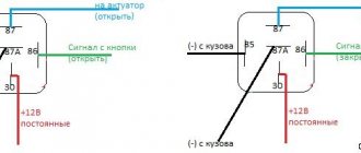
The main block of the engine compartment is equipped with 11 relays, the purpose of some of which depends on whether a diesel or gasoline engine is installed on the car:
- R1 - foglights and rear lights. Models without fog lights have a jumper;
- R2 — radiator blower fan, if air conditioning is not installed;
- R3 — fans on;
- R4 — headlight washer;
- R5 - X-contact of the unloading relay (indicated by the number 214 in the latest generations);
- R6 — cabin fans (manually controlled air conditioning), air conditioning fan for speed at the 2nd stage (automatically controlled air conditioning);
- R7 - sound signal;
- R8 - sound alarm relay for anti-theft system (cars with manual transmission). Cars without anti-theft devices have a jumper installed, while cars equipped with automatic transmissions have a free slot;
- R9 — interval mode of glass cleaner;
- R10 — fuel pump, single injection;
- R11 - radiator fan to turn on the 1st stage of rotation /
In the Audi 80 B4 with a diesel engine, 2 and 3 relays are in reserve, and R10 is responsible for the preheating plugs. You also need to take into account that in the B4 generation the relay, designated by the number 208, is responsible for the fuel pump, while in the B3 – 215.
The additional relay block, which is located under the steering wheel in the car interior, has the following description, in general terms, preserved from the birth of the B2 and especially B3 generations in 1989.
There are 18 relays in total, their designations are deciphered:
- ABS systems.
- Seat belt warning light.
- Interior lighting control unit.
- Air conditioner clutch relay unit.
- Rear window wiper and washer system.
- Oil pressure monitoring devices, front lighting control unit, the breakdown of which can be found out if this relay clicks.
- Not used.
- Not used.
- Automatic gear shift lock (only for vehicles with automatic transmission).
- —
- —
- Heated seats.
- Heated driver's seat.
- Sunroof on the car roof.
- Sunroof ECU and power door windows.
- Likewise.
- Anti-theft alarm warning lights.
- Power door windows, power sunroof, power seat circuit breaker.
Turn signal fuses and relays
Located in the engine compartment block number 15 with a power of 25 Amps. There is no turn signal relay in the factory configuration; the connection is carried out by the car owner independently. Its absence or breakdown is indicated by a buzzing sound.
Cigarette lighter fuse
Since 1988, in all generations of the Audi 80, it is located in the block under the hood at number 4 and has a power of 15 A.
Cooling Fan
Elements 17 and 20 of the engine compartment block correspond. The second protects the switching system. The power of both is 30 A.
Low beam
The fuses in the Audi 80 are numbered 10 and 11, with a power of 10 Amperes. They are located in the block under the hood.
Power window fuses and relays
They are located inside the car. ESP relays are numbered 15 and 16.
Luke
In the cabin there are four relays of the interior engine unit - 14, 15, 16 and 18.
Instrument lighting
It is located in the engine compartment block number 14. Its power is 5 Amperes.
Wipers
There are no fuses.
Stove
There are no such fusible elements in the factory configuration.
Signal fuses and relays
The brake light insert for the Audi 80 has number 29, a power of 10 Amperes and is located in the engine compartment block.
Radio tape recorder
The fusible element is not included in the factory configuration.
High beam
The 8th and 9th elements of the main block of the engine compartment, each with a power of 10 Amperes, are responsible for it.
Dashboard
Its operation is protected by fuse No. 12 for 15 Amps of the main unit.
Reverse
Are protected by fuse 12.
central locking
It is protected by 10 Amp element #19 in the main unit.
Generator fuse and relay
The current regulator in the Audi 80 does not have its own inserts as standard, but this is not an expensive item and it is expected that car owners will install it themselves.
Dimensions
Protection is provided by 5 A elements 6 and 7, which are located in the main block of the engine compartment.
Speedometer
Does not have its own fuse as standard.
Washer
A fusible element responsible for protecting the windshield wiper No. 15 with a power of 15 A. 5 relays of the additional unit are responsible for the same element.
Audi 80 fuel pump relay: where is it located
Fuel pump insert No. 13 and power 15 A, located in the main block. There is also a relay number 10. If the latter breaks down, you need to check which engine is installed in the Audi - AVK or AVT, since this determines which device you need to choose.
Where is the starter relay located?
For all types of motor, including ABK 2 0, it is installed additionally. Its price is not high.
Glow plugs
This relay is present only in cars with a diesel engine, where it is installed at number 10 in the cabin block.
Emergency crew
This relay is not installed at the factory.
Unloading relay for headlights
Relay No. 5 of the cabin unit is responsible for unloading in the Audi 80.
Oil pressure control relay
Responsible for No. 6 in the additional block.
Charging relay
For Audio 80 with a diesel engine, this is element No. 5 of the additional unit.
Ignition
Audio 80 is not included in the factory configuration.
Fuses, relays, their location and purpose
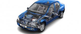
| Most power supply circuits for vehicle electrical equipment are protected by fuses. Headlights, electric fan motors, fuel pump and other powerful consumers are connected via a relay. Fuses and relays are installed in mounting blocks, which are located in the car interior on the side of the instrument panel on the left side and in the engine compartment on the left and right sides of the battery. |
The fuses can be removed and checked visually. If you are unable to remove the fuse by hand, you can use special tweezers. A blown fuse can be easily identified by the damaged element. You can also test the fuse for continuity using an ohmmeter or an open circuit tester—if there is no continuity, the fuse is blown. Each fuse is marked with a rating. Please note that the fuse can only be replaced with a fuse of the same rating. Spare fuses are located in the fuse box. If you use a spare fuse, always replace it as soon as possible so that you always have spare fuses of different ratings in the box.
Warning! Never install a fuse of a higher rating or connect wire terminals with improvised means instead of using a fuse, as this may cause damage to the electrical circuit and a fire.
If the fuse is blown, be sure to check the electrical circuit for signs of a short circuit. Check the system for exposed wires or wires with frayed, melted, or burnt insulation. If you replace a fuse before determining what caused it, the new fuse will also blow.
Sometimes a fuse may blow or cause an electrical circuit to open for no apparent reason.
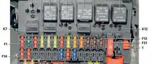
Corrosion of the fuse and fuse block terminals can cause damage to the fuse contacts. If this occurs, remove any traces of corrosion using a wire brush or sandpaper, then spray the fuse terminals with electrical contact cleaner. Fuses, their numbers and assignments located in the passenger compartment
| Most fuses are installed in the mounting fuse block in the passenger compartment (the block cover in the instrument panel is removed), located at the left end of the instrument panel under a plastic cover. Circuits protected by fuses (shown in the photo) are shown in the table |
| Table: Circuits protected by fuses |
| Fuse no. | Fuse color | Protected circuit |
| F1 (20 A) | Yellow | Windshield wiper |
| F2 (5 A) | Beige | Instrument cluster, ECU |
| F3 (20 A) | Yellow | Reversing lights, brake lights |
| F4 (10 A) | Red | Airbag |
| F5 | Red | Same |
| F6 | Reserve | Place for installing a security alarm |
| F7 | Reserve | Trailer |
| F8 | — | — |
| F9 (10A) | Red | Left headlight (low beam) |
| F10 (10 A) | Red | Right headlight (low beam |
| F11 (10 A) | Red | Left headlight (high beam) |
| F12 (10 A) | Red | Right headlight (high beam) |
| F13 (30 A) | Green | Rear electric window |
| FJ4 (30 A) | Green | Front electric window |
| F15 (10 A) | Red | ABS |
| F16 (15 A) | Reserve | Electrically heated seats |
| F17 (15 A) | Blue | Sound signal |
| F18 (10 A) | Red | Left side marker light |
| F19 (7.5 A) | Red | Right side marker light |
| F20 (7.5 A) F21 (5 A) | Brown Beige | Rear fog lamp Heated exterior mirrors |
| F22 | — | — |
| F23 | Reserve | Place for installing a security alarm |
| F24 | — | — |
| F25 | — | — |
| F26 | — | — |
| F27 | — | — |
| F28 (15 A) | Blue | Interior lighting |
| F29 (15 A) | Blue | General nutrition |
| F30 (20 A) | Yellow | Blocking of opening body elements |
| F31 (15 A) | Blue | Fog lights |
| F32 (30 A) | Green | Heated rear window |
| F33 | — | — |
| F34 | — | — |
| F35 | — | — |
| F36 (30 A) | Green | Heating (air conditioning) and interior ventilation system |
| F37 (5 A) | Beige | Electric exterior mirrors |
| F38 (10 A) | Red | Car radio |
| F39 (30 A) | Green | Heating (air conditioning) and interior ventilation system |
same in the picture
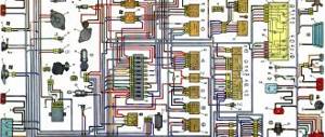
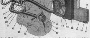
| In addition, the relays and fuses are located in the mounting block in the engine compartment (the cover of the mounting block is removed). In table 10.2 indicates the designations of the blocks and the purpose of the installed relays and fuses. It should be borne in mind that a specific car model may not have some of the circuits listed in the table and the positions of the blocks may differ. |
1st option for the location of fuses in the engine compartment
| 10.2b. Numbers of relays and fuses in the mounting block located in the engine compartment (left side) |
| 10.2a. Numbers of relays and fuses in the mounting block located in the engine compartment (right side) |
table 10.2
| Relay/fuse box | Relay/fuse number | Relay/fuse assignment |
| 597A | F1 (60 A) | Security alarm, exterior lighting switch, daytime running light relay (block 1034) |
| F2 (60 A) | Exterior lighting switch, interior fuse box | |
| 597V | F1 (30 A) | Relay board power supply |
| F2 (25 A) | Injection relay power supply circuit | |
| F3 (5 A) | Injection relay power supply circuit, injection computer | |
| 597C | F1 (50 A) | ABS ECU |
| F2 (25 A) | ABS ECU | |
| 597D | F1 (40 A) | High speed fan relay (relay 236), relay board |
| 299 | 231 (20 A) | Fog lights |
| 753 (20 A) | Headlight washer pump | |
| 784 | 474 (20 A) | Air conditioning compressor relay |
| 700 (20 A) | Low speed fan relay | |
| 1034 | 288 (20 A) | Daytime running light relay |
| 289 (20 A) | Same | |
| 290 (20 A) | » | |
| 1047 | 236 (20 A) | Fuel pump relay |
| 238 (20 A) | Injection blocking relay | |
| Separate relays | 233 (40 A) | Heater Fan Relay |
| 236 (40 A) | High speed fan relay |
also in the picture is the 2nd location option
| Fuse designation (rated current, A) | Protected elements |
| F01 (60 A) | Circuits: power supply to the ignition switch and all consumers powered from the lock; outdoor lighting switch |
| F02 (30 A) | Power circuit turnip short circuit of the cooling fan (on a car without air conditioning) |
| F03 (25 A) | Power circuits: relay K5 of the fuel pump and ignition coil: main relay K6 of the engine management system |
| F04 (5 A) | Circuits: constant power supply to the engine control system ECU; windings of the main relay K6 of the engine control system |
| F05 (15 A) | Not used |
| F06 (60 A) | Interior fuse box power supply circuit |
| F07 (40 A) | Power circuits: air conditioning relay K4; low speed short circuit relay for the cooling system fan (on a car with air conditioning); relay K2 high speed cooling fan (on a car with air conditioning) |
| F08 (50 A) and F09 (25 A) | ABS computer circuits |
also in the picture
RELAY:
| Designation | Name | Powered consumers |
| K1 | Heater fan turnip | Heater fan motor |
| K2 | Repair high speed fan system | Cooling fan motor (for vehicle with air conditioning) |
| short circuit | Low speed system fan turnip | Cooling fan motor (for vehicles with air conditioning) (for vehicles with air conditioning - via resistor) or cooling fan relay (for vehicles without air conditioning) |
| K4 | Air conditioner relay | Air conditioning compressor electromagnetic clutch |
| K5 | Fuel pump and ignition coil relay | Fuel pump and ignition coil |
| K6 | Engine control system main relay | Oxygen concentration sensor (heating circuit); speed sensor; fuel injectors; adsorber purge solenoid valve; relay windings K2. KZ. K4 |
| K7 (optional) | Headlight washer pump relay | Headlight washer pump |
| K8 | Fog light relay | Fog lamps |
same in the picture
Replacing fuses
| 1. To gain access to the mounting block, remove the cover in the instrument panel. |
| THE NOTE |
| On the inside of the cover there is a diagram of the location of the relays and fuses, as well as spare fuses 1 of various ratings and plastic tweezers 2 for removing fuses from the mounting block. |
| 2. Before replacing a blown fuse, find out the cause of its blown and eliminate it. When troubleshooting, look at the information listed in the table. 10.1 circuits that this fuse protects. |
| ATTENTION Do not replace fuses with jumpers or fuses designed for a different amperage, as well as homemade jumpers - this can lead to damage to electrical devices and even a fire. |
| 3. Remove the replacement fuse using tweezers. |
| 4. This is what a blown fuse looks like (the jumper inside the holder shown by the arrow has burned out and opened). To replace a fuse, use a spare fuse of the same rating (and color). |
| NOTE Spare fuses of different ratings are located on the back of the mounting block cover. |
| 5. To access the mounting block located in the engine compartment, press the left... | 6. ...and right cover latches... |
| 7. ...then remove the cover of the mounting block.. |
| 8. If replacement is necessary, remove the relay (fuse) by rocking it from side to side. |
| 9. Install the parts in the reverse order of removal. |
How to remove the fuse box
Carry out the procedure with great care so as not to damage anything. For this:
- lift the hood lid;
- disconnect the negative terminal of the battery;
- the interior unit is hidden by a lid with handles that pull towards you;
- unscrew the screws holding the mounting frame;
- under the frame, unscrew the 4 screws holding the block itself;
- Unscrew the screws and remove the block.