Electrical diagram of VAZ-1111 and VAZ-11113 cars
Oka cars use a single-wire circuit for connecting electrical equipment, i.e., only one wire is suitable for all electricity consumers. The second “wire” connecting consumers to sources of electricity is the car body, or “ground”. This scheme allows you to significantly reduce the number of wires and simplify their installation. The negative terminals of the electricity sources are connected to ground. With this connection, the corrosion of metal body parts due to electrochemical corrosion is reduced.
The sources of electricity in a car are a generator and a battery connected in parallel. The rated operating voltage of electricity sources and consumers is 12 V. However, the voltage in the electrical equipment system, depending on specific conditions, can range from 11 to 14.5 V, and within these limits, consumers remain operational.
All electrical equipment of cars can be divided into the following main systems:
- power system, including a battery and a generator with a voltage regulator;
- engine starting system, which includes the starter, starter relay and corresponding ignition switch contacts;
- ignition system, consisting of an ignition coil, spark timing sensor, switch, spark plugs, high voltage wires, ignition relay and corresponding ignition switch contacts;
- lighting and light signaling system, combining headlights, lanterns and corresponding switches and relays;
- control devices with sensors;
- additional electrical equipment, which includes a windshield and rear window cleaner and washer, a rear window heating system, a heater motor, a cigarette lighter and a sound signal.
The operation and activation of all systems is controlled by corresponding switches and relays. The supply voltage is supplied to most consumers through the ignition switch 31. The switched circuits for different key positions are shown in the table (see also Chapter 32).
The power circuits of those electrical equipment components whose operation may be required under any circumstances are always connected to the battery and generator (regardless of the position of the key in the ignition switch). These components include the sound signal 4, the cigarette lighter 45, the threads of the brake signal lamps in the rear lights 68, the license plate lights 70, the interior light 58 and the plug socket 11 for a portable lamp. Also directly connected to the power supply are the hazard warning circuits, side light circuits and the high beam headlight signaling circuit.
When operating vehicles, short circuits may occur due to damage to the insulation of wires or electrical equipment components. They cause a sharp increase in current in a short-circuited circuit and, if protective measures are not taken, can lead to rapid discharge of the battery, overheating of the wires, melting of their insulation and fire of the car upholstery.
To protect against short circuits, the vehicle has 11 fuses. Ten of them are located in a plastic block 22, and one fuse 32, protecting the target of the rear fog light, is located in a separate housing in the wiring harness near the rear fog light switch 41. This fuse is rated for a maximum current of 8 A.
The fuse box is located under the instrument panel on the left side of the steering column. Fuses are a thin plate of low-melting metal mounted on a plastic base. Seven fuses (black) are rated for a maximum current of 8 A, and three (green) are rated for 16 A. 16 A fuses are located in the power circuits of electrical components that consume high current (such as the rear window heating element, cigarette lighter, electric motor engine cooling fan, etc.).
The following are the circuits protected by the fuses located in the fuse box.
If a fuse blows, it is recommended to check the circuits it protects, repair the fault that caused the blown, and then install a new fuse. It is not allowed to use any homemade fuses or fuses that are not provided for by the design of the vehicle.
The largest number of fuses is installed in the lighting system, since it has the most extensive and extensive network of wires and is therefore most susceptible to damage and short circuits to ground. The electric motors of the windshield and rear window wipers are additionally protected from overloads by thermobimetallic fuses located in the electric motors themselves. The cigarette lighter is additionally protected from prolonged use by a low-melting alloy washer located in the rear part of the cigarette lighter.
Some electrical power supply circuits do not have fuses at all. As a rule, these are the most critical systems, the trouble-free operation of which is required in emergency situations. For example, the engine ignition system is not protected by fuses, so as not to introduce into it elements that reduce the reliability of the system in operation. If the ignition system fails, the engine will stop running. There are also no fuses in the starting circuit, so as not to reduce the reliability of engine starting. In addition, the battery charging circuit, as well as the relay for turning on the high and low beam headlights, are not protected by fuses.
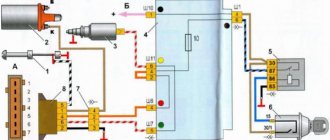
General scheme
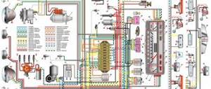
The general diagram of the electrical equipment of the VAZ 11113 is presented below:
1 – turn signal repeater; 2 – front turn signal; 3 – headlight; 4 – el. fan motor with cooling; 5 – signal; 6 – fan switching sensor; 7 – el. washer pump motor; 8 – spark supply moment sensor; 9 – battery; 10 – starter; 11 – switch; 12 – candles; 13 – coil; 14 – generator; 15 – temperature sensor; 16 – oil pressure sensor; 17 – 12 V socket; 18 – windshield wiper relay; 19 – brake fluid level sensor; 20 – brake light switch; 21 – el. windshield wiper motor; 22 – el. carburetor magnetic valve; 23 – reverse light switch; 24 – starter relay; 25 – low beam relay; 26 – high beam relay; 27 – alarm relay; 28 – cigarette lighter; 29 – electric switch. stove motor; 30 – extra electric resistor stove motor; 31 — lighting switch; 32 – safety block; 33 — PTF power supply fuse; 34 – relay for turning on the rear window heater; 35 – electric switching relay. fan motor with cooling; 36 – parking brake control relay; 37 – rear window heater and washer switch; 38 – rear window heater switch; 39 – rear PTF switch; 40 – carburetor suction control; 41 – alarm switch; 42 – ignition switch; 43 – ignition relay; 44 – el. stove motor; 45 – fuel sensor; 46 – lamp switch; 47 – dashboard; 48 – windshield wiper switch; 49 – glass washer pump switch; 50 – signal switch; 51 – light switch; 52 – turn signal switch; 53 – brake light switch; 54 – interior lamp; 55 – carburetor suction control switch; 56 – el. rear window washer motor.
Oka - fuses and relays
Oka is a general designation for a family of cars also known as VAZ 1111, VAZ-11113 (LADA OKA), SeAZ-1111, KamAZ-1111, Astro 11301.
Produced with various modifications from 1987 to 2008. In this publication you will find a description of fuses and relays in an OKA car with block diagrams and their locations. Note the fuse responsible for the cigarette lighter. In conclusion, we suggest that you familiarize yourself with the OKA electrical circuit.
p, blockquote 1,0,0,0,0 —>
p, blockquote 2,0,0,0,0 —>
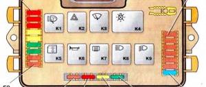
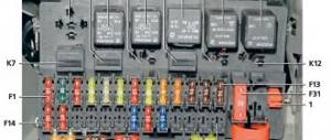
Fuse box
The main fuse box is located in the passenger compartment under the dashboard on the driver's side.
p, blockquote 3,0,0,0,0 —>
p, blockquote 4,0,1,0,0 —>
The numbering goes from left to right, from 1 to 10 and will be printed on the block cover.
p, blockquote 5,0,0,0,0 —>
p, blockquote 6,0,0,0,0 —>
Description
p, blockquote 7,0,0,0,0 —>
| 1 | 16A Heater fan electric motor, Relay (winding) and sensor for turning on the electric motor of the engine cooling system fan, Relay (winding) for turning on the rear window heating, Electric motors for the rear window wiper and washer, windshield washer |
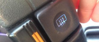
| 2 | 8A Carburetor solenoid valve, Windshield wiper relay and motor, Turn signals and relay-interrupter for turn signals and hazard warning lights (in turn signal mode), Turn signal warning lamp, Tail lights (reversing lamps), Alternator field winding (at start-up) engine), Carburetor choke warning lamp, Relay breaker and warning lamp for parking brake system and insufficient brake fluid level, Oil pressure warning lamp, Battery discharge warning lamp, Coolant temperature indicator, Fuel level indicator with reserve warning lamp |
| 3 | 8A Left headlight (high beam), High beam indicator lamp |
| 4 | 8A Right headlight (high beam) |
| 5 | 8A Left headlight (low beam) |
| 6 | 8A Right headlight (low beam) |
| 7 | 8A Left headlight (side light), Left rear light (side light), License plate lights, Side light warning lamp |
| 8 | 8A Right headlight (side light), Right rear light (side light), Instrument cluster lamp, Cigarette lighter lamp |
| 9 | 16A Direction indicators and relay-breaker for direction indicators and hazard warning lights in hazard mode, Rear window heating element and relay (contacts) for its activation |
| 10 | 16A Electric motor of the engine cooling system fan and relay (contacts) for turning it on, Sound signal, Plug socket for a portable lamp, Interior lighting, Tail lights (brake lamps). Cigarette lighter |
Fuse number 10 at 16A is responsible for the operation of the cigarette lighter.
Replacing fuses on Oka
The PSU installation process is quite simple and intuitive. At the preparation stage, we check the availability of:
- Collar;
- Heads on "10";
- A new old-style power supply unit (cylindrical type) or a knife type, if the owner decided to upgrade;
- Additional lighting as needed if work is carried out in conditions of limited visibility.
- Place the car on a flat surface, open the driver's door wide;
- We wedge the rear row of wheels with wheel chocks and squeeze the parking brake lever. This is necessary for personal safety during work;
- Open the hood, unscrew the power terminals from the battery to prevent a short circuit in the on-board circuit;
- We snap off the cover from the power supply unit and squeeze the plastic clips on the sides;
- Using a 10mm socket, unscrew the mounting bolts on the sides. We remove the power supply from the seat.
Next, we insert a power supply with knife-type fuses; if we are upgrading the equipment or identifying a faulty module, we replace it with a new one.
- Screw the bolts and put on the protective cover.
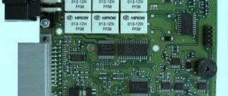
Additional relays
Depending on the configuration and design, additional relay placement is possible.
p, blockquote 13,0,0,1,0 —>
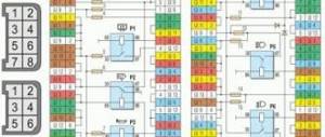
Scheme
p, blockquote 14,0,0,0,0 —>
p, blockquote 15,0,0,0,0 —>
Purpose
p, blockquote 16,0,0,0,0 —>
- Hazard warning and direction indicator relay (494.3747 / 2105-3747010-01) - located behind the instrument cluster.
- Front wiper relay (RS-514 (2101-5205150)) - located under the upholstery, left side panel.
- Parking brake warning lamp relay (RS-492 (2101-3803150)) - located behind the instrument cluster, next to the turn signal relay (see point 1).
- Additional relay (90.3747-10 / 113.3747-10 / 2105-3747210-20).
- Ignition relay (90.3747-10 / 113.3747-10 / 2105-3747210-20) - secured with a self-tapping screw from inside the instrument panel.
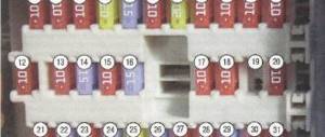
Circuit breakers
Location
The fuse box is located inside the car under the instrument panel, on the left side of the steering column.
Description
1 (16A) - Heater fan electric motor / Relay (winding) and sensor for turning on the engine cooling fan electric motor / Relay (winding) for turning on the rear window heating / Electric motors for the rear window wiper and washer and windshield washer
2 (8A) - Carburetor solenoid valve / Relay and windshield wiper motor / Turn signals and relay-interrupter for turn signals and hazard warning lights (in turn signal mode) / Turn signal warning lamp / Rear lights (reversing lamps) / Field winding generator (when starting the engine) / Carburetor choke warning light / Relay breaker and warning light for parking brake system and insufficient brake fluid level / Oil pressure warning light / Battery discharge warning light / Coolant temperature gauge / Fuel level gauge with warning light reserve
3 (8A) - Left headlight (high beam) / High beam indicator lamp
4 (8A) - Right headlight (high beam)
5 (8A) - Left headlight (low beam)
6 (8A) - Right headlight (low beam)
7 (8A) - Left headlight (side light) / Left rear light (side light) / License plate lights / Side light indicator lamp
8 (8A) - Right headlight (side light) / Right rear light (side light) / Instrument cluster lamp / Cigarette lighter lamp
9 (16A) - Direction indicators and relay-breaker for direction indicators and hazard warning lights in hazard mode / Heated rear window element and relay (contacts) for its activation
10 (16A) - Electric motor of the engine cooling system fan and relay (contacts) for turning it on / Sound signal / Socket for a portable lamp / Interior lighting / Rear lights (brake lamps) / Cigarette lighter
Location
A block of five relays is located in the car interior under the instrument panel, on the left side of the steering column.
Fuse installation diagram
| Marking | Scheme |
| Fuse (1) / 15 | Stove heater |
| Fuse (2) / 10 | Fan activation sensor |
| Fuse (3) / 5 | Windscreen wipers |
| Fuse (4) / 5 | Carburetor solenoid valve |
| Fuse (5) / 15 | Turn signals. Alarm |
| Fuse (6) / 20 | Tail lights, oil pressure, battery |
| Fuse (7) / 20 | High beam, low beam, dimensions |
| Fuse (8) / 15 | License plate light |
| Fuse (9) / 5 | Power socket, interior lighting |
| Fuse (10) / 5 | Cigarette lighter |
The cost of the original fuse block assembly (hereinafter referred to as the BP) starts from 1,200 rubles. high-quality analogues from 800 rubles.