The Hall sensor of the VAZ 2107 is one of the most necessary components in the car’s ignition system. If it fails, then interruptions in the operation of the power plant may begin and it is quite possible that the car will stop completely.
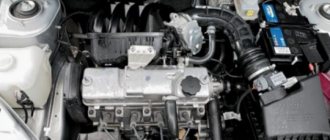
The Hall sensor on the VAZ 2107 is a control device that is a camshaft controller, which is installed near the distributor and guarantees its correct operation. The breaker-distributor shaft has a special plate in the shape of a crown. This plate has special slots, and there is a magnet on the camshaft controller. As the camshaft rotates, metal vanes enter the controller space. As a result, a pulse voltage is generated that goes to the ignition coil, and it is converted into an increased voltage. The ultimate goal is the spark plugs.
Ignition operation diagram
It should be noted that the VAZ 2107 camshaft controller has only 3 terminals. One is connected to the minus, and the other supplies a voltage of six volts, the 3rd one transmits the impulse directly to the switch.
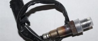
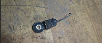
VAZ Hall sensor
How to recognize the problem
If you suspect that the Hall controller on a VAZ has begun to malfunction, before replacing it you need to make sure that it is the problem. This is determined by the following criteria:
- the power unit starts with difficulty or does not start at all;
- the engine runs jerkily, the speed is uneven;
Power point
- jerking when driving at high speeds;
- unpredictable engine operation - it can stop at any time.
Verification method
Experts recommend the following methods for checking the Hall sensor of a VAZ family car before replacing it:
- The easiest and most reliable is to borrow a proven or new sensor from someone and install it to replace your own. If the engine operation has returned to normal, then you need to go to the store and buy a new one.
- The second method is to measure the output voltage using a tester. A working sensor produces a voltage of 0.4-11 Volts.
- The next option can be called an imitation of the work of the Hall controller. It is not difficult to master; you need to pull out the block with 3 plugs from the controller itself. Next, turn on the ignition and connect the 3rd and 6th outputs. If there is a spark, then most likely the cause of interruptions in the system should be looked for in another unit, but not in the sensor.
Signs of sensor failure
There are a number of signs that indicate a malfunction of the sensor in question, namely:
- problems starting the engine;
- interruptions and unstable idle speed;
- car jerking at high speeds;
- The car regularly stalls when driving.
These signs may indicate other problems, but checking the Hall sensor will not be superfluous. The symptoms described may also indicate problems with the carburetor or injector.
Replacement
If you are convinced that the problem is with the Hall sensor, then you can replace it yourself. This is not difficult and any motorist can handle it if desired. There is no point in overpaying the service station technicians; you can check it yourself and handle the replacement yourself.
Tools
You will need this screwdriver
Stages
It is advisable to carry out work in a well-lit room.
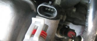
Correct connection of the block
- First of all, it is necessary to remove the distributor itself from the car and then unscrew the cover.
- Next, pull up a little and remove the slider.
- Remove the plastic cover.
- The plug is secured with a bolt and needs to be unscrewed.
- Let's take him out.
- The sensor plate is held on by bolts that need to be unscrewed.
- The vacuum corrector is fixed with bolts, we also unscrew them.
- Remove the retaining ring.
- We remove the traction and the corrector itself.
- To get the wires you need to move the clamps apart.
- Remove the support plate.
- Now all that remains is to unscrew a couple of bolts and remove the Hall sensor.
- We install a new one.
- Assembly work is performed in reverse order.
Important! If any signs of breakdown occur, do not delay repairs. Check the Hall controller immediately and replace it if necessary.
As you can see, everything is very, very simple. It is worth spending just an hour of your time to save several thousand rubles, which you will have to pay to the service station.
Self-check video
This video shows how to properly check the Hall sensor of a VAZ car.
How to check and replace sensor on a VAZ 2107
?
Sensor
Hall VAZ
2107
is one of the most necessary components in the car ignition system. If it fails, then interruptions in the operation of the power plant may begin and it is quite possible that the car will stop completely.
Sensor
Hall on the VAZ
2107 is a control device, which is a camshaft controller, which is installed near the distributor and guarantees its correct operation.
The breaker-distributor shaft has a special plate in the shape of a crown. This plate has special slots, and there is a magnet on the camshaft controller. As the camshaft rotates, metal vanes enter the controller space. As a result, a pulse voltage is generated that goes to the ignition coil, and it is converted into an increased voltage. The ultimate goal is the spark plugs. Ignition operation diagram
2107 camshaft controller has only 3 terminals. One is connected to the minus, and the other supplies a voltage of six volts, the 3rd one transmits the impulse directly to the switch.
VAZ sensor
Hall
KEY-DOP
How to change the Hall sensor on a VAZ 2107
How to check and replace VAZ Hall 2107 sensor
?
sensor
VAZ Hall
2107
. This is one of the most important components of a car's ignition system. In the event of a failure, the powertrain may be interrupted, and it is quite possible that the machine will come to a complete stop.
sensor
VAZ Hall
2107 .
This monitoring device is a camshaft controller that is installed next to the distributor and ensures its correct operation. The distributor switch shaft has a special crown-shaped plate. This plate has special slots, and a magnet is installed on the camshaft. When the camshaft rotates, metal vanes enter the controller space. As a result, a pulse voltage is generated, which is supplied to the ignition coil and turns into high voltage. Final goal. spark plug. Ignition circuit
It should be noted that the VAZ camshaft controller 2107 has only 3 terminals. One is connected to minus, and the other. supplies a voltage of six volts, third. transmits the impulse specifically to the switch.
Vazovsky sensor
hall
How to identify the problem
If you suspect that the Inspector Hall on the VAZ has begun to fail before replacing it, then you need to make sure that it has a problem. This is determined by the following criteria:
- the power supply hardly starts or never starts;
- the engine runs jerkily and rotates unevenly;
READ Replacement Timing Chain Opel 2 2 Diesel
Exit
- jerking when moving at high speed;
- unpredictable engine operation. he can stop at any moment.
VAZ 2107 CARBURETOR. REPLACEMENT OF HALL SENSORS
I RECOMMEND RESPONSIBLE AZ-1 VEHICLE DELAY AND RESERVE REQUIREMENTS
Test method
Experts recommend replacing the following methods for checking the Hall sensor of a VAZ family car:
- The simplest and most likely way. borrow something new or proven from someone. sensor
and replace it with your own. If everything is fine with the engine, then you need to go to the store and buy a new one. - Second way. measure the output voltage using a tester. working sensor
produces a voltage of 0.4-11 volts. - Another variant. simulate the operation of the Hall controller. To master this is not difficult, you need to remove the block of 3 plugs from the controller itself. Then turn on the ignition and connect the 3rd and 6th outputs. If a spark occurs, it is likely that the cause of the system failure should be sought in another unit, and not in the sensor.
replacement
If you are sure that the Hall sensor is the problem, then you can replace it yourself. It is not difficult, and any car enthusiast can handle it if desired. There is no point in overpaying the WTO specialists; you can check it yourself and make the replacement yourself.
READ How to Change the Rubber Band on a Windshield Wiper Blade
tools
I need this screwdriver
Stages
It is advisable to carry out work in a well-lit room.
Correct connection of pads
- First, remove the distributor directly from the machine and then unscrew the cap.
- Then lightly tug the slider, pulling it up.
- Remove the plastic cover.
- The plug is screwed in and must be unscrewed.
- We're taking it out.
- The touch plate rests on screws that need to be unscrewed.
- We secure the vacuum concealer with bolts and also unscrew them.
- Remove the retaining ring.
- Remove the rod and the corrector itself.
- To get the wires, you need to move the clamps.
- Remove the backing.
- Now you need to unscrew a couple of bolts and remove sensor
. - We're putting in a new one.
- Installation work is carried out in reverse order.
How to change the Hall sensor on a VAZ 2107 |
Important! If there are any signs of damage, do not delay repairs. Check the Hall controller immediately and replace if necessary.
As you can see, everything is very, very simple. It’s worth spending just an hour of your time to save several thousand rubles that you have to pay to your service stations.
Self-test video
Verification method
Experts recommend the following methods for checking the Hall sensor of a VAZ family car before replacing it:
- sensor
from someone and install it to replace your own. If the engine operation has returned to normal, then you need to go to the store and buy a new one. - The second method is to measure the output voltage using a tester. working sensor
produces a voltage of 0.4-11 Volts. - The next option can be called an imitation of the work of the Hall controller. It is not difficult to master; you need to pull out the block with 3 plugs from the controller itself. Next, turn on the ignition and connect the 3rd and 6th outputs. If there is a spark, then most likely the cause of interruptions in the system should be looked for in another unit, but not in the sensor.
KEY-DOP
How to check the Hall sensor
A simple way to check the camshaft position (Hall) sensor is shown in the following video.
There are several ways to check the health of the Hall sensor. Each motorist can choose the most suitable option for himself:
- Take a working sensor from a neighbor or at a car disassembly for testing and install it instead of the “native” one. If the engine problems disappear, then you will have to buy a new part.
- Using a tester, you can measure the voltage at the sensor output. In a working device, the voltage will vary from 0.4 V to 11 V.
- You can create a simulation of a Hall sensor. To do this, remove the three-pin block from the distributor. Then turn on the ignition and connect outputs 3 and 6 of the switch with a piece of wire. The appearance of a spark indicates that the sensor has failed.
This is interesting: Where is the cabin filter located and when does it need to be changed?
If the test reveals that the Hall sensor is faulty, then it must be replaced with a new one.
Checking the sensor with a multimeter
You can check the DH in different ways. One popular diagnostic option is a multimeter or voltmeter. This verification method has two options. Let's look at how to check a car's hall sensor in both cases.
1st method
To carry out diagnostics, you need to find a working voltmeter or multimeter that is set to measure DC voltage (direct current) in the range of 20 Volts. In addition, you will need to stock up on 2 iron pins, through which the DC will be checked.
Before checking the hall sensor, you will need to remove the rubber boot from the block, which is connected to the distributor and directly to the DH.
- remove the main armored wire from the distributor;
- We connect it to the arrester or to ground.
This is done in order to exclude the accidental occurrence of a discharge, because this may contribute to starting the engine during the test.
- turn on the ignition;
- remove the block from the distributor;
- set the mode on the multimeter to DC 20 V;
- We connect the negative terminal of the device to ground (any part of the car body);
- the positive probe of the device will serve as a voltage meter.
The block going to the distributor has three wires: red, green and white (colors may be different). On the red wire, the voltage of the device should show 11.37 or close to 12 V. On the green or middle wire, the value is also close to 12 V. And finally, on the last - white wire, the value is 0.
By the way, if you put the device in the audio test mode, then placing the probe on the contact, you will hear a constant ringing, which will indicate that the white wire is connected to ground. That's how it should be.
What did the preliminary check give? We made sure that the households received all the necessary impulses.
Continue (multimeter in DC measurement mode):
- We take the prepared pins (studs) and thread them like this: one into the green (middle wire), the other into the white (ground wire);
- We connect the block in its place, in the car distributor.
Why are pins needed? They play the role of a current conductor. There are no contacts on the back of the block, and the values can only be checked if the wires are exposed. This is not recommended, which is why the pins are inserted.
- take the multimeter clamps (ignition is on);
- We connect the positive terminal of the multimeter to the pin of the middle wire of the block, and the negative terminal to the other (white wire).
In this position, the multimeter value should be within 11.2 V.
- crank the crankshaft while simultaneously observing the instrument readings;
- if the instrument readings drop to 0.02 V (lower measurement limit) and rise to 11.8 V (upper measurement limit) when cranking the crankshaft, then this is considered normal.
Attention. The DC is considered to be in good working order if, when cranking the crankshaft, the upper limit of measurement is no less than 9 V, and the lower limit is no more than 0.4 V.
Thanks to these measurements, we checked the performance of the DC installed in the car distributor.
2nd method
The second verification method differs from the first in that this time the DH is diagnosed autonomously. In other words, it will not be connected to the ignition system - to the switch.
So, to carry out this method you will need a homemade assembly of 3 contacts inserted into the distributor block, plus/minus pins and 2 test points for measurements. The homemade assembly diagram will look like this
Here's what to do:
- Connect the three homemade contacts to the connectors where the original distributor block is inserted (if the sensor is removed, then to its terminals);
- supply plus/minus power to the homemade assembly;
- connect the plus of the multimeter to one control point for measurement, the minus to the other;
- turn the crankshaft.
Again, the upper limit of measurement on a working sensor should not be lower than 9 V, and the lower limit should not be higher than 0.4 V.
If the DH is removed from the car, then it will be checked as follows:
- the sensor leads are connected to the homemade assembly (the other connections are the same as in the case described above);
- take a knife or curtain and draw the blade along the slot in the DH.
When the curtain is closed, the DC readings are above 9 V, and when the curtain is open, they are below 0.4 V.
Thus, using a multimeter, you can check the DC for serviceability in 2 simple ways. Of course, there are many other options for checking the sensor, but they are more difficult to carry out, although they provide instant access to the DH.
A general familiarity with the operating principle of DCs, despite the gradual displacement of contactless ignition systems by multiprocessor ones, will provide many benefits in the future. So, this can help the car owner when using other car sensors that operate on the Hall principle: speed sensor, camshaft position, etc.
This is interesting: Why does the muffler shoot: a list of reasons for popping noises in car operation
Forget about fines from cameras! An absolutely legal new product - Traffic Police Camera Jammer, hides your license plates from the cameras that are installed in all cities. More details at the link.
- Absolutely legal (Article 12.2);
- Hides from photo and video recording;
- Suitable for all cars;
- Works through the cigarette lighter connector;
- Does not cause interference to radios and cell phones.
If you find an ERROR, please select a piece of text and press Ctrl+Enter (on Windows) Cmd+Enter (on Mac).
Jerking of the car, problems with starting the engine, interruptions in engine operation - these and other problems may indicate a breakdown of the Hall sensor.
other methods
If the symptoms of a Hall sensor malfunction do not convince you that it is the problem, you can try measuring the resistance on the sensor. Here you yourself will have to act as a designer and make a device whose constituent parts are:
We solder a resistance to one leg of the LED, and 2 wires to it. We choose the length of the wires ourselves - so that it is more convenient to work. We dismantle the distributor cover, disconnect the plug assembly and the distributor. Then we diagnose the electrical circuit. To do this, connect the voltmeter to terminals 1 and 3, and activate the car’s ignition. If the unit is working correctly, a value of 10-12 volts will appear on the screen.
Then we connect the device made for measurement to the same terminals. The LED will definitely light up if the polarity is selected correctly. If this does not happen, the wires must be swapped. Then we proceed like this:
- leave the wire connected to the first terminal alone;
- transfer the third terminal to the second;
- crank the camshaft (manually or using a starter).
The principle is simple: if the LED blinks when the shaft is turned, it means everything is working and the sensor is in order. Checking sensors on different car models is carried out according to the same scheme.
You can also ask your friends to borrow a device that is known to work. Contact car enthusiasts whose cars have identical sensors. If the problems disappear, this means that the DC on your car is faulty.
Stages
It is advisable to carry out work in a well-lit room.
Correct connection of the block
- First of all, it is necessary to remove the distributor itself from the car and then unscrew the cover.
- Next, pull up a little and remove the slider.
- Remove the plastic cover.
- The plug is secured with a bolt and needs to be unscrewed.
- Let's take him out.
- The sensor plate is held on by bolts that need to be unscrewed.
- The vacuum corrector is fixed with bolts, we also unscrew them.
- Remove the retaining ring.
- We remove the traction and the corrector itself.
- To get the wires you need to move the clamps apart.
- Remove the support plate.
- Now all that remains is to unscrew a couple of bolts and remove sensor
. - We install a new one.
- Assembly work is performed in reverse order.
Self-check video
This video shows how to properly check sensor of a VAZ car.
When the Hall sensor on a VAZ 2107 breaks down, this makes it impossible to continue driving. The Hall sensor belongs to the category of key parts of a contactless ignition system, and if this part begins to fail, the switch will stop sending impulses to produce a spark. To troubleshoot the problem, you need to understand in detail the purpose and operation of the device.
Why is a Hall sensor needed and how does it work?
The device of the contactless ignition system of the VAZ 2107 car has such an element called a Hall sensor. Its fundamental purpose is the ability to detect the angle of the crankshaft and camshaft of the power unit. The Hall sensor is not installed on injection models of sevens, it is installed only on carburetor ones.
According to the value of this device, voltage pulses are supplied to the spark plugs. The functioning of this element is based on increasing the voltage in the cross-section of a wire placed in a magnetic field. The element is connected by three terminals, two of which provide power supply (plus and minus), and the third contact is intended directly for supplying a signal. The device received this name due to a special effect that was identified by scientist Hall. In the distributor on the shaft there is a plate that is part of the control of the device controller.
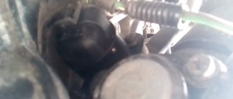
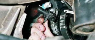
When the motor operates, the metal in the slots alternately changes, and the magnet, which is located inside the controller, begins to be excited by oscillations of the magnetic field. In this case, the controller generates voltage pulses issued by the switch and supplied to the coil. The coil, in turn, raises the voltage to a high value and transports it one by one through armored wires to the spark plugs. Knowing the operating features, you need to deal with the malfunctions, but before that it is important to note that the Hall sensor on the VAZ 2107 is located in the distributor under the cover. To replace it, you will need to disassemble the distributor.
Basic sensor malfunctions
Any part on a car sooner or later begins to malfunction, and the Hall sensor is no exception, even though it has the simplest design. Its breakdown is detected by detecting the following defects:
- Inability to start the engine.
- Unstable and unstable operation of the motor.
- The occurrence of jerks.
- The engine begins to stall.
- The appearance of the detonation effect.
If the above symptoms appear, then there is no need to rush to change the Hall sensor, since similar phenomena can also occur due to other breakdowns of the ignition and fuel supply system. To verify that the device is faulty, you will need to perform a suitability test.
Check Features
The BSZ contactless ignition on the VAZ 2107 has a Hall sensor, the serviceability of which determines the normal operation of the internal combustion engine. If you suspect that it is faulty, then you need to check the Hall sensor. To do this, there are different ways on the basis of which one can draw a conclusion about the suitability of the element.
The following two methods are used to check an element:
- The simplest test method is to install a known-good element. If the signs of malfunctions immediately disappear, it means that the breakdown was detected correctly and successfully repaired. The disadvantage of this method is that you must first purchase a working element.
- Use a multimeter to check the voltage at the sensor output. The device switches on the voltage measurement mode, after which the value at the device output is measured. The value should be between 0.4 and 11 Volts, and if this is not the case, the element should be replaced.
- Simulation of device operation. The test diagram is as follows - the element terminal should be removed from the connector, and then turn on the ignition. Now we begin to simulate the operation of the Hall sensor, for which contacts 3 and 6 of the switch output are connected. If sparking occurs, the element must be replaced.
Types of Hall sensors
Hall effect sensors can be divided into two types:
- Based on the Conclusion
- Based on operation
Linear (analog) Hall sensors
In linear sensors, the Hall voltage (voltage on edges A and C) will depend on the magnetic field strength. Or in simple words, the closer we bring the magnet to the sensor, the greater the Hall voltage will be. This is a linear relationship.
In linear Hall sensors, the output voltage is taken directly from the operational amplifier. That is, in linear sensors you will not see a Schmitt trigger, nor an output switching transistor. That is, it will all look something like this:
What does the voltage on faces A and C depend on? Mainly from a magnetic field created by either a permanent magnet or an electromagnet; the thickness of the plate, as well as the strength of the current flowing through the plate itself.
Theoretically, if a very strong magnetic flux is applied to the Hall sensor, then the Hall voltage will be infinitely large? No matter how it is). The output voltage will be limited by the supply voltage. That is, the graph will look something like this:
As you can see, up to a certain point we have a linear dependence of the sensor output voltage on the magnetic flux density. Further increase in the magnetic flux is useless, since it has reached the saturation voltage, which is limited by the supply voltage of the Hall sensor itself.
Thanks to these parameters, using a Hall sensor, devices were built that made it possible to measure the current strength in a conductor without touching the wire itself, for example, current clamps.
There are also instruments that can be used to measure the magnetic field strength. Hall sensors used in these devices are called linear , since the voltage across the Hall sensor is directly proportional to the magnetic flux density.
This is interesting: How to adjust headlights with your own hands - a detailed explanation of popular adjustment methods
Linear sensors, as I already said, can be used in current clamps. They allow you to measure current ranging from 250 mA to several thousand Amperes. The biggest advantage in such current clamps is the absence of mechanical contact with the measured circuit. In other words, Hall effect current meters are much safer than shunt and ammeter based meters, especially when the circuit current is high, which is often found in industrial installations.
Digital Hall sensors
As soon as the era of digital electronics began, various logic elements began to be placed in one housing along with a Hall sensor. We have already reviewed the simplest Hall sensor on a Schmitt trigger above and it looks like this:
In fact, such a sensor has only two output states. Either the signal is present (logical one) or it is not (logical zero). The hysteresis on the Schmitt trigger simply eliminates frequent switching, which is why it is always used in digital Hall sensors.
As a result, the industry began to produce Hall sensors for digital electronics. Basically, such sensors are divided into three types.
Unipolar Hall sensor
As the name suggests, these sensors only require the positive magnetic field of the magnet's south pole to activate as well as release the sensor.
Bipolar
We bring the magnet to one pole - the sensor will work and will continue to work even when we remove the magnet from the sensor. In order to turn it off, we need to apply a different magnet polarity to it.