A stepper motor is a synchronous brushless motor with multiple windings. The current supplied to one of the stator windings causes the rotor to lock. Sequential activation of the motor windings causes discrete angular movements of the rotor, also known as steps. This is why the motor is called a stepper motor. To control a stepper motor, a special controller is used, which is called a stepper motor driver.
Stepper motors are standardized by the National Electrical Manufacturers Association (NEMA) for mounting and flange sizes. The most popular sizes are NEMA 17 with a 42*42mm flange, NEMA 23 with a 57*57mm flange and NEMA 34 with a size of 86*86mm, respectively. NEMA 17 stepper motors can produce torque up to approximately 6 kg*cm, NEMA 23 up to 30 kg*cm and NEMA 34 up to 120 kg*cm.
How does a stepper motor work?
Structurally, stepper motors can be divided into three large classes: motors with variable magnetic reluctance, motors with permanent magnets, and a hybrid class that combines the characteristics of the first two.
Stepper motors with variable reluctance have several poles on the stator and a rotor made of soft magnetic material that does not retain residual magnetization. For simplicity, the rotor in the figure has 4 teeth and the stator has 6 poles. The motor has 3 independent windings, each of which is wound on two opposite poles of the stator. The motor in the picture has a pitch of 30 degrees.
When the current is turned on in one of the coils, the rotor tends to take a position where the magnetic flux is closed, i.e. the rotor teeth will be opposite those poles on which the powered winding is located. If you then turn off this winding and turn on the next one, the rotor will change position, again closing the magnetic flux with its teeth. Thus, in order to carry out continuous rotation, you need to turn on the phases alternately. This type of motor is not sensitive to the direction of current in the windings, and due to the fact that the rotor is not magnetic, this type of motor can operate at high speeds. It is also easy to distinguish this type of motor from other steppers by simply rotating it by the shaft when it is turned off. The shaft will spin freely, while other types will clearly feel steps. Sometimes the surface of each stator pole is geared, which, together with the corresponding rotor teeth, reduces the pitch angle to several degrees. Motors with variable magnetic reluctance are now almost never used.
Permanent magnet motors consist of a stator with windings and a rotor containing permanent magnets. Due to the magnetization of the rotor, such motors provide greater magnetic flux and, as a result, greater torque than motors with variable reluctance.
The motor shown in the figure has 3 pairs of rotor poles and 2 pairs of stator poles. The stator has 2 independent windings, each of which is wound on two opposite poles. The engine in the figure has a step size of 30 degrees, the same as the previous one. When the current is turned on in one of the coils, the rotor tends to take a position where the opposite poles of the rotor and stator are opposite each other and to achieve continuous rotation it is necessary to switch on the phases alternately. In practice, permanent magnet motors typically have 48 to 24 steps per revolution, corresponding to pitch angles of 7.5 to 15 degrees).
In practice, a permanent magnet motor looks, for example, like this. You can see such an engine in a laser printer. Permanent magnet motors are subject to back EMF from the rotor, which limits the maximum speed. This means that during a free run at high speeds, the engine will act as a generator and can burn the driver with current, which it generates itself. The same applies to hybrid engines.
Hybrid motors combine the best features of variable reluctance stepper motors and permanent magnet motors. Hybrid stepper motors provide smaller steps, higher torque, and higher speeds than variable reluctance motors and permanent magnet motors.
Typical steps per revolution for hybrid engines range from 100 to 400, corresponding to pitch angles of 3.6 to 0.9 degrees. The rotor of the motor shown in the figure has 100 poles (50 pairs), the motor has 2 phases, so the total number of poles is 200, and the pitch, accordingly, is 1.8 degrees.
A hybrid engine looks like this, for example.
Most modern stepper motors are hybrid, so let's take a closer look at the design of stepper motors of this type.
The motor rotor is divided transversely into two parts, between which there is a cylindrical permanent magnet. Due to this, the teeth of the upper half of the rotor are the north poles, and the teeth of the lower half are the south poles. In addition, the upper and lower halves of the rotor are rotated relative to each other by half the pitch angle of the teeth. The number of pairs of rotor poles is equal to the number of teeth on one of its halves. The toothed rotor pole pieces, like the stator, are assembled from separate plates to reduce eddy current losses. The stator of a hybrid motor also has teeth, providing a large number of equivalent poles as opposed to the main poles on which the windings are located. Typically 4 main poles are used for motors with 3.6 degree pitches and 8 main poles for 1.8 and 0.9 degree pitches. Rotor teeth provide less resistance to the magnetic circuit at certain rotor positions, which improves static and dynamic torque. This is ensured by the appropriate arrangement of the teeth, when part of the rotor teeth is strictly opposite the stator teeth, and part is between them.
Let's look at the longitudinal section of a hybrid stepper motor. The arrows indicate the direction of the magnetic flux of the permanent magnet of the rotor. Part of the flux (shown as a black line in the figure) passes through the rotor pole pieces, air gaps and the stator pole piece. This part is not involved in creating momentum.
As can be seen in the figure, the air gaps at the upper and lower pole pieces of the rotor are different. This is achieved by turning the pole pieces by half the tooth pitch, which was very clearly visible in the previous photo. Therefore, there is another magnetic circuit that contains minimal air gaps and, as a result, has minimal magnetic resistance. This circuit closes another part of the flow (shown in the figure by a dashed white line), which creates the moment. Part of the chain lies in a plane perpendicular to the figure, so it is not shown. The magnetic flux of the stator coil is created in the same plane. In a hybrid motor, this flux is partially closed by the rotor pole pieces and has little effect on the permanent magnet. Therefore, unlike DC motors, the magnet of a hybrid stepper motor cannot be demagnetized at any level of winding current.
The gap between the rotor and stator teeth is very small, about 0.1 mm. This requires high precision during assembly, so the stepper motor should not be disassembled to satisfy curiosity, otherwise its service may end.
To prevent the magnetic flux from closing through the shaft that passes inside the magnet, it is made of non-magnetic steel grades. To obtain large torques, it is necessary to increase both the field created by the stator and the field of the permanent magnet. This requires a larger rotor diameter, which worsens the torque to inertia ratio. Therefore, powerful stepper motors are sometimes constructed from several sections in the form of a stack. Torque and moment of inertia increase in proportion to the number of sections, and their ratio does not deteriorate.
We looked at the design of the hardware of stepper motors itself, but in addition to this, motors can also be divided according to the number and method of switching their windings.
There are only two main types - bipolar and unipolar.
A bipolar motor has one winding in each phase, which must be reversed by the driver to change the direction of the magnetic field. This type of motor requires a bridge or half bridge driver. In total, the bipolar motor has two windings and, accordingly, four outputs. An example of a common bipolar motor would be the 17HS4401 stepper motor
A unipolar motor also has one winding in each phase, but a tap is made from the middle of the winding. This allows you to change the direction of the magnetic field created by the winding by simply switching the winding halves. At the same time, the driver circuit is significantly simplified, which in the case of a unipolar motor should have only 4 simple keys. The middle terminals of the windings can be combined inside the motor, so such a motor can have 5 terminals, as in the figure, or 6 terminals if terminals AB and CD are separated. A unipolar motor with two windings and taps can be used in bipolar mode if the taps are left unconnected.
An example of a common five-lead unipolar motor would be the 28BYJ-48 brand stepper motor. This motor can be converted into a bipolar one by separating the AB and CD terminals, for which it is enough to cut one of the jumpers on the board under the blue cover.
Sometimes motors have 4 separate windings, for this reason they are mistakenly called 4-phase or four-winding motors. Each winding has separate terminals, so there are 8 terminals in total. With the appropriate connection of the windings, such a motor can be used both as unipolar and bipolar.
If we compare bipolar and unipolar motors, then bipolar motors have a higher power density, which means that with the same dimensions, bipolar motors provide greater torque. The torque produced by a stepper motor is proportional to the magnitude of the magnetic field created by the stator windings. There are two ways to increase the magnetic field - this is by increasing the current or the number of turns of the windings. A natural limitation when increasing the winding current is the danger of saturation of the iron core, but in practice a much more significant limitation is the limitation on motor heating due to losses due to the ohmic resistance of the windings. This is where the advantage of the bipolar motor design comes into play. In a unipolar motor, only half of the windings are used at any given time, and the other half simply takes up space in the core window, which forces the windings to be made with smaller diameter wire or the dimensions of the motor to be increased. At the same time, in a bipolar motor all windings are always working. In other words, on a bipolar motor of the same power it is necessary to wind half as much copper winding wire as on a unipolar one, and if the windings are equal in mass, then the bipolar motor will be about 40% more powerful.
In practice, you can find both types of motors, since bipolar ones are cheaper due to lower material consumption, while unipolar ones require much simpler drivers. Currently, hybrid bipolar engines are the most widely used.
Where to buy SD?
You can buy stepper motors in our 3DIY store with delivery throughout Russia!
Position of stepper motor viburnum
It is clear that the information was taken from the Internet, but I also downloaded it for myself. Maybe someone else will find it useful
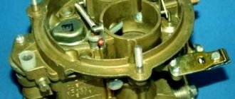
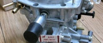
Throttle assembly
At first glance, the throttle valve assembly is a simple mechanical device. It houses a throttle position sensor and a stepper motor (XX regulator). As a whole, this unit must meet strict technical conditions. Deviation of the characteristics of the throttle valve assembly from these specifications significantly affects the behavior of the engine in transient modes: acceleration, braking, coasting, idling, engine starting. The serviceability of the throttle position sensor and the stepper motor do not guarantee the correct operation of the system if the mechanics and design of the throttle valve are of poor quality. The throttle valve assembly is a device in the system through which the driver sets the required vehicle speed. By pressing the throttle (gas) pedal, it changes the flow rate of the intake manifold to supply air to the engine. The second task of the throttle assembly is to maintain the bypass channel (XX channel) in such a mode that if the driver refuses to control the throttle (switching off the gearbox, braking, coasting - in all these cases the throttle valve is closed), this channel provides the necessary filling of the engine with air to maintain crankshaft rotation speeds specified by the system. This mode is implemented using a stepper motor installed in the throttle valve assembly. Poor quality of the throttle valve assembly (non-compliance with specifications), as a rule, causes the following malfunctions:
• Slowly decrease engine speed after closing the throttle valve.
• Difficulty starting a hot engine with a closed throttle.
• The engine stalls when the load is suddenly reduced (transmission switched off, coasting).
The listed malfunctions can also be caused by other reasons, for example, malfunctions in the ignition system, fuel supply, or a malfunction of the air flow sensor. But these malfunctions, if they exist, also appear in other engine operating modes.
Throttle Position Sensor (TPS)
The TPS is located on the throttle valve assembly and determines the degree of opening of the throttle valve. The system uses throttle sensor readings for the following operating modes:
1. In the engine start mode, the fuel supply is adjusted according to the degree of throttle opening (increases when the throttle is open). But when the throttle is opened more than 90%, the system stops supplying fuel to the engine. In this mode, you can purge the engine when cranking with the starter.
2. While the car is moving, when the throttle sensor readings are above a certain value, the system, taking into account the engine speed, provides a power supply mode. The calculation of the injector opening time depending on the air flow is determined by the parameter of enriching the composition of the fuel-air mixture according to tables hardwired into the memory of the control unit. In standby modes, if the mass flow sensor fails, the readings of the throttle sensor determine the filling of the cylinders with air to calculate the fuel supply to the engine and set the ignition timing.
3. In operating modes, the throttle position 0% means entering the idle mode. In this case, the system’s task is to maintain a given level of crankshaft rotation speed depending on the temperature sensor readings and vehicle speed. The control unit tries to reduce engine speed by controlling the fuel supply blocking mode to the limit from which the software idle speed controller is activated, which, using a stepper motor and ignition timing, ensures stable engine operation at a given speed.
You need to understand that the system uses the readings of the throttle position sensor not only to determine the operating mode (idling, power mode, purging the engine at startup, operation in reserve modes), but also corrects the fuel supply to the engine depending on the rate of change of the throttle position (in analogy with a carburetor - an accelerator pump). The service life of sensors from Russian manufacturers leaves much to be desired. Erasure of the resistive layer on the internal contacts of the sensor can lead to a number of system malfunctions. Switching to a contactless sensor will help improve the situation. As a rule, the sensor readings are violated in the positions where it most often works - this is the zero (or close to it) throttle position.
Typical system malfunctions due to a faulty throttle sensor:
• Freezing of idle speed at 1500-3000 depending on the engine temperature (This is a reserve mode of operation of the system, it is caused by a sensor malfunction, the system in this case does not regulate the idle speed).
Stepper motor control
Regardless of which driver or motor is used, the stepper motor can be controlled in one of three modes:
- full step
- half-step
- microstepping
The full-step motor control mode implies alternating phase switching without overlapping, while only one of the phases is connected to the voltage source at a time. With this control method, there is one phase for each complete step of the electric motor and the rotor equilibrium points are identical to the stator poles. This mode also has a drawback: in the case of a bipolar motor in full-step mode, only half of the windings are activated at the same moment, with a unipolar motor - a quarter. There is another option for full-step control, which involves simultaneous activation of two phases. This method of motor control is based on fixing the rotor between the stator poles due to the supply of power to the windings, with two phases per full step. With this control method, the rotor equilibrium point is shifted by half a step relative to the single-phase method, and the torque increases by approximately 40 percent.
The use of a half-step control mode for a stepper motor allows you to double the number of steps per rotor revolution. When the motor operates in this mode, every second step one of the phases is turned on, and between steps both are turned on at once. In fact, it is a combination of alternating single-phase and two-phase full-step modes.
The microstep motor control mode is used when it is necessary to obtain the largest possible number of steps per rotor revolution. When operating in this mode, two phases also operate, but the winding currents in this case are distributed unevenly, and not 50/50, as in half-stepping. The microstep size depends on the specific device and driver settings. When operating in microstepping mode, the positioning accuracy of the motor is significantly increased, but a more complex motor driver is required.
Where can I buy SD drivers?
You can buy stepper motor drivers in our online store with delivery!
Design versions of SD
Conventional stepper motor
There are no frills here - the body, shaft, in general are standard. Widely used in various equipment, ranging from milling cutters and 3D printers to damper or stirrer drives.
Hollow shaft motor
Hollow shaft stepper motors are used when there is a need to transmit torque without the use of couplings, for example for use in confined spaces. You can also thread a long shaft through it, which will stick out on both sides and synchronously rotate something on one side and the other.
Motor with drive nut integrated into the shaft
This type of engine can be used when fast movement over long distances is required. A long screw at high speeds behaves like a jump rope, and when using such a motor, the screw can be pulled motionless between the supports, and the motor itself can be mounted on a moving part of the equipment. Then the length and non-rigidity of the screw will not affect the maximum speed.
Double shaft motor
In this design, the engine has an extended shaft, the long end of which protrudes from the rear cover. You can hang a lamb on this extended shaft so that you can set the position of the shaft manually, hang an encoder and get a servostepping motor, or you can hang an additional pulley or screw that will work absolutely synchronously with the front shaft.
Engine with a propeller instead of a shaft
They find application, for example, in 3D printers or in any other place where you want to save space not only on the coupling between the shaft and the propeller, but also on the bearing support of the propeller, the role of which in this case is played by the motor bearings.
Motor with built-in brake
Allows you to fix the shaft in the desired position in addition to holding it with the stepper itself. It also allows you to hold the shaft in the event of a power failure to the engine.
Motor with gearbox
The gearbox allows you to lower engine speed and increase its torque. This design is rare due to the fact that stepper motors already have significant torque at low speeds and can themselves reach very low rotation speeds.
Motor with encoder
It's also a servostepping motor. In fact, it is a servo drive on a stepper motor. An encoder in the housing is mounted on the extended shaft on the side of the back cover and thanks to this we receive feedback about the position of the motor shaft. If the motor skips steps, the controller will know about this and, based on the encoder readings, will supply additional pulses until the shaft reaches the desired position. The servostepper motor is used with its own special driver, which has an input for connecting an encoder.
Advantages of Stepper Motor
- The angle of rotation of the rotor is determined by the number of pulses supplied. The stepper motor does not rotate smoothly, but in steps; the step has a certain value. Therefore, in order to rotate the shaft to the desired position, we simply apply a known number of pulses.
- position dependence on input pulses ensures positioning without feedback. One step - one impulse. No matter how many pulses were given, the engine moved to that position.
- The engine provides full torque when stopped. This is good because the powered motor does not need a brake to fix the position of the shaft; it can be braked using the driver.
- Precise positioning and repeatability. Good stepper motors have an accuracy of 3 to 5% of the step size. This error does not accumulate from step to step, since per one revolution of the engine there is a constant number of steps, after completing which we will always get a turn of 360 degrees.
- high reliability. High engine reliability is associated with the absence of brushes. The service life is actually determined by the service life of the bearings
- possibility of obtaining low rotation speeds. To obtain a low engine rotation speed, it is enough to slow down the pulse rate, then the engine will move more slowly and its rotation speed will be low.
- high torque at low speeds. High torque at low speeds eliminates the need for a gearbox, which simplifies the design of the equipment
- A fairly large range of speeds can be covered. The rotation speed of the motor is proportional to the frequency of the input pulses; by supplying them faster or slower, we also influence the rotation speed.
Connecting a stepper motor
To power the windings, you will need a device capable of delivering a control pulse or a series of pulses in a certain sequence. Such blocks are semiconductor devices for connecting a stepper motor and microprocessor drivers. Which have a set of output terminals, each of them determines the power supply method and operating mode.
Depending on the connection diagram, one or another output of the stepper unit should be used. With various options for connecting certain terminals to the DC output signal, a certain rotation speed, step or microstep of linear movement in the plane is obtained. Since some tasks require a low frequency, while others require a high one, the same motor can set the parameter at the expense of the driver.
Typical SD connection diagrams
Depending on the number of pins present on a particular stepper motor: 4, 6 or 8 pins, the possibility of using one or another connection diagram will also differ. Look at the pictures, typical options for connecting a stepper mechanism are shown here:
Connection diagrams for various types of stepper motors
Provided that the main poles of the stepper machine are powered from the same driver, according to these diagrams the following distinctive features of operation can be noted:
- The leads are clearly connected to the corresponding terminals of the device. When connecting windings in series, the inductance of the windings increases, but the current decreases.
- Provides the passport value of electrical characteristics. In a parallel circuit, the current increases and the inductance decreases.
- When connecting one phase per winding, the torque at low speeds is reduced and the magnitude of the currents is reduced.
- When connected, it carries out all electrical and dynamic characteristics according to the passport, rated currents. The control scheme is greatly simplified.
- Produces much more torque and is used for high rotation speeds;
- Like the previous one, it is designed to increase torque, but is used for low rotation speeds.
Disadvantages of a stepper motor:
- The phenomenon of resonance is inherent in a stepper motor. Stepper motors have their own resonant frequency. This is due to the fact that the rotor, after applying current to the winding, oscillates for some time before locking in the final position, and the greater the inertia of the rotor, the stronger the oscillations. Resonance leads to increased noise, vibration and a drop in engine torque. One way to combat resonance is to increase the pitch division. Small movements in microsteps do not require long acceleration and fixation of the rotor; they quickly stop it between steps and increase the stepping frequency above the resonant one.
- Possible loss of position control due to operation without feedback. If the shaft force exceeds what the motor can produce, it will begin to skip steps. Since the motor has no feedback, the controller cannot find out about this and even if the motor starts to rotate again, it starts from the wrong operating position. To eliminate this drawback, you can use a servostepper motor or increase the torque on the shaft by increasing the voltage, setting the driver to a higher current, or replacing the motor with a more powerful one.
- consumes energy regardless of load. The stepper motor is fixed in the intermediate position with full torque. He also walks with full momentum. Therefore, it continues to consume electricity without much dependence on the load on the shaft. We can reduce the overall energy consumption of the motor by using drivers that reduce the current supplied in hold mode.
- difficult to work at high speeds. At high rotation speeds, the stepper motor significantly loses torque and when a certain speed is reached, the torque becomes so small that the shaft cannot rotate any further. At this moment, the engine stops and hums at the frequency of the supplied pulses. This drawback can be eliminated by increasing the supply voltage, which will increase the torque at both high and low speeds, using a more advanced driver that switches to a full-step motor control mode at high rotation speeds, or simply replacing the stepper with a servo drive that is designed for high speeds. speed.
- low specific power. In terms of specific power per gram of weight, a stepper motor is not the most energy-dense electric drive. We can't do anything about it.
- relatively complex control circuit. Stepper motor drivers are rich in electronics. We cannot change anything here either.
Stepper Motor Types
To ensure various operating parameters, both the step size by which the shaft will move and the moment applied for movement are important. Variations in these parameters are achieved due to the design of the rotor itself, the connection method and the design of the windings.
By rotor design
The rotating element provides magnetic interaction with the electromagnetic field of the stator. Therefore, its design and technical features directly determine the operating mode and rotation parameters of the stepper unit. In order to practically determine the type of stepper motor, with the network de-energized, you need to turn the shaft; if you feel resistance, this indicates the presence of a magnet; otherwise, it is a design without magnetic resistance.
Reactive
A reactive stepper motor is not equipped with a magnet on the rotor, but is made of soft magnetic alloys; as a rule, it is made of plates to reduce induction losses. The design in cross section resembles a gear with teeth. The poles of the stator windings are powered by opposite pairs and create a magnetic force to move the rotor, which moves from the alternating flow of electric current in the winding pairs.
With variable magnetic reluctance
A significant advantage of this stepper drive design is the absence of a stopping moment generated by the field in relation to the reinforcement. In fact, this is the same synchronous motor in which the rotor rotates in accordance with the stator field. The disadvantage is the reduction in torque. The pitch for a jet engine ranges from 5 to 15°.
With permanent magnets
In this case, the moving element of the stepper motor is assembled from a permanent magnet, which can have two or more poles. Rotation of the rotor is ensured by the attraction or repulsion of the magnetic poles by the electric field when voltage is applied to the corresponding windings. For this design, the angular step is 45-90°.
With permanent magnet
Hybrid
It was developed to combine the best qualities of the two previous models, due to which the unit has a smaller angle and pitch. Its rotor is made in the form of a cylindrical permanent magnet, which is magnetized along the longitudinal axis. Structurally, it looks like two round poles, on the surface of which there are rotor teeth made of soft magnetic material. This solution made it possible to provide excellent holding and torque.
Hybrid stepper motor design
The advantages of a hybrid stepper motor are its high accuracy, smoothness and speed of movement, small steps - from 0.9 to 5°. They are used for high-end CNC machines, computer and office equipment and modern robotics. The only drawback is the relatively high cost.
As an example, let’s look at the option of hybrid motors with 200 shaft positioning steps. Accordingly, each of the cylinders will have 50 teeth, one of them is a positive pole, the second is negative. In this case, each positive tooth is located opposite the groove in the negative cylinder and vice versa. Structurally it looks like this:
Location of hybrid grooves
Because of this, there are 100 alternating poles with excellent polarity on the stepper motor shaft. The stator also has teeth as shown in Figure 6 below, except for the spaces between its components.
Rice. 6. Operating principle of a hybrid stepper motor
Due to this design, it is possible to achieve a displacement of the same south pole relative to the stator in 50 different positions. Due to the difference in the position in the half-position between the north and south poles, the ability to move in 100 positions is achieved, and the phase shift by a quarter division makes it possible to double the number of steps due to sequential excitation, that is, up to 200 steps of the angular shaft per 1 revolution.
Pay attention to Figure 6, the principle of operation of such a stepper motor is that when current is supplied in pairs to opposite windings, the opposite poles of the rotor, located behind the stator teeth, are pulled together and the like poles, going in front of them in the direction of rotation, are repelled.
By type of windings
In practice, a stepper motor is a polyphase motor. The smoothness of operation in which directly depends on the number of windings - the more there are, the smoother the rotation occurs, but also the higher the cost. In this case, the torque does not increase from the number of phases, although for normal operation their minimum number on the electric motor stator must be at least two. The number of phases does not determine the number of windings, so a two-phase stepper motor can have four or more windings.
Unipolar
A unipolar stepper motor differs in that the winding connection diagram has a branch from the middle point. This makes it easy to change magnetic poles. The disadvantage of this design is that only half of the available turns are used, resulting in less torque being achieved. Therefore, they are distinguished by their large dimensions.
Unipolar SD
To use the full power of the coil, the middle terminal is left unconnected. Consider the designs of unipolar units; they may contain 5 and 6 leads. Their number will depend on whether the middle wire is brought out separately from each motor winding or whether they are connected together.
Scheme a) with different, b) with one output
Bipolar
The bipolar stepper motor is connected to the controller via 4 pins. In this case, the windings can be connected internally both in series and in parallel. Consider an example of his work in the figure.
Bipolar stepper motor
In the design diagram of such a motor you see one excitation winding in each phase. Because of this, changing the direction of the current requires the use of special drivers (electronic chips designed for control) in the electronic circuit. A similar effect can be achieved by turning on the H-bridge. Compared to the previous one, the bipolar device provides the same torque with much smaller dimensions.
How to choose a stepper motor? What parameters to pay attention to.
By and large, choosing an engine comes down to choosing a few things:
- type of engine (its dimensions)
- phase current
- inductance
As for the type of motor, in the absence of any specific preference, we would recommend using bipolar stepper motors with 4 leads, since they are the most common and, just as important, drivers for them are equally common. That is, in case of any breakdown, you can easily find a replacement and repair the machine. The easiest way to select the size of the motor and its current is by focusing on ready-made machines from well-known manufacturers that are close to the design in size and characteristics - a proven design means that the motors have already been optimally selected and their characteristics can be taken as a basis. The engine manufacturer in this case is not particularly important, since due to proven production technology, their characteristics are approximately the same from different manufacturers. One characteristic remains - inductance.
At the same supply voltage, motors with higher inductance have more torque at low speeds, and less torque at high speeds, as can be seen from the graph. But higher inductance potentially allows you to get more torque by increasing the supply voltage, whereas with low inductance motors, increasing the voltage can cause the motor to overheat without noticeably improving performance. This is due to the fact that the current rises faster in windings with low inductance and we can easily get an average current value higher than the rated value, and as a result, overheating. Thus, all other things being equal, it is better to choose a motor with a large inductance value.