Design features of the brake system
8.1.
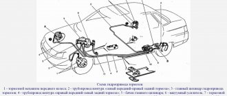
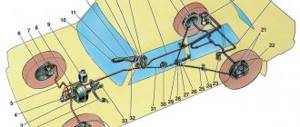
Diagram of the hydraulic brake drive: A – flexible hose of the front brake; B – flexible hose of the rear brake; 1 – front wheel brake mechanism; 2 – left front–right rear brake circuit pipeline; 3 – main cylinder for hydraulic brakes; 4 – pipeline of the right front–left rear brake circuit; 5 – master cylinder reservoir; 6 – vacuum booster; 7 – rear wheel brake mechanism; 8 – elastic lever of the pressure regulator drive; 9 – pressure regulator; 10 – pressure regulator drive lever; 11 – brake pedal
The car uses a working brake system with diagonally separated circuits (Fig. 8.1), which significantly increases the safety of driving the car. One hydraulic drive circuit ensures the operation of the right front and left rear brake mechanisms, the other - the left front and right rear. If one of the circuits of the service brake system fails, the second circuit is used to stop the vehicle with sufficient efficiency.
The hydraulic drive includes a vacuum booster 6 and a dual-circuit pressure regulator 9 in the rear brakes.
The parking brake system is driven by the brake mechanisms of the rear wheels.
8.6. Front wheel brake:
1 – brake disc; 2 – pad guide; 3 – caliper; 4 – brake pads; 5 – working cylinder; 6 – piston; 7 – sealing ring; 8 – protective cover of the guide pin; 9 – guide pin; 10 – protective casing
Front wheel brake
disc, with automatic adjustment of the gap between the pads and the disc, with a floating bracket.
The bracket is formed by caliper 3 (Fig. 8.6) and working cylinder 5, tightened with bolts. The movable bracket is bolted to pins 9 installed in the holes of the shoe guide. Lubricant is placed in these holes, rubber covers 8 are installed between the pins and the pad guide. The brake pads 4 are pressed against the grooves of the guide by springs.
A piston 6 with a sealing ring 7 is installed in the cavity of the cylinder 5. Due to the elasticity of this ring, the optimal gap between the brake pads and the disc is maintained. In a variant, cars can be equipped with pads with a pad lining wear indicator.
8.7. Rear wheel brake:
1 – hub fastening nut; 2 – wheel hub; 3 – lower tension spring of the pads; 4 – brake pad; 5 – guide spring; 6 – working cylinder; 7 – upper tension spring; 8 – expansion bar; 9 – finger of the parking brake drive lever; 10 – parking brake drive lever; 11 – brake shield
8.8. Rear wheel brake working cylinder:
A – slot on the thrust ring; 1 – block stop; 2 – protective cap; 3 – cylinder body; 4 – piston; 5 – seal; 6 – support plate; 7 – spring; 8 – crackers; 9 – thrust ring; 10 – thrust screw; 11 – fitting
Rear wheel brake
(Fig. 8.7) drum, with automatic adjustment of the gap between the shoes and the drum. The automatic clearance adjustment device is located in the working cylinder. Its main element is a split thrust ring 9 (Fig. 8.8), installed on the piston 4 between the shoulder of the thrust screw 10 and two nuts 8 with a gap of 1.25–1.65 mm.
The thrust rings 9 are inserted into the cylinder with tension, providing a shear force of the ring along the cylinder mirror of at least 343 N (35 kgf), which exceeds the force on the piston from tension springs 3 and 7 (see Fig. 8.7) of the brake pads.
When, due to wear of the linings, the gap of 1.25–1.65 mm is completely selected, the shoulder on the thrust screw 10 (see Fig. 8.8) is pressed against the shoulder of the ring 9, as a result of which the thrust ring moves after the piston by the amount of wear. When the braking stops, the pistons are moved by the force of the tension springs until the cracks stop against the shoulder of the thrust ring. This automatically maintains the optimal gap between the pads and the drum.
8.9. Parking brake system drive:
1 – lever fixation button; 2 – parking brake drive lever; 3 – protective cover; 4 – traction; 5 – cable equalizer; 6 – adjusting nut; 7 – lock nut; 8 – cable; 9 – cable sheath
Parking brake system
with a mechanical drive, acts on the brake mechanisms of the rear wheels. The parking brake drive consists of lever 2 (Fig. 8.9), adjusting rod 4, equalizer 5, cable 8, lever 10 (see Fig. 8.7), manual pad drive and expansion bar 8.
8.10. Emergency brake fluid level sensor:
1 – protective cap; 2 – sensor housing; 3 – sensor base; 4 – sealing ring; 5 – clamping ring; 6 – reflector; 7 – pusher; 8 – bushing; 9 – float; 10 – fixed contacts; 11 – moving contact
Emergency brake fluid level sensor
mechanical type.
Housing 2 (Fig. 8.10) of the sensor with seal 4 is pressed to base 3 by clamping ring 5 screwed onto the neck of the tank. At the same time, the reflector flange 6 is pressed against the end of the neck. In this position, the clamping ring is held by two clamps made on the base 3.
A pusher 7 passes through the base hole, connected to the float 9 using a bushing 8. There is a movable contact 11 on the pusher, and fixed contacts 10 are located on the sensor body. The contact cavity is sealed with a protective cap 1.
When the level of brake fluid in the reservoir drops to the maximum permissible level, the moving contact moves down onto the fixed contacts and closes the circuit of the brake system emergency warning lamp in the instrument cluster.
Useful tips: There are two ways to bleed the brakes without an assistant.
- The first is the most reliable: order a turner an aluminum or bronze cover for the main brake cylinder, screw the valve from the brake chamber into it and connect it to the spare wheel with an additional hose; air pressure should not exceed 0.05–0.07 MPa (0.5–0.7 kgf/cm2).
- The second is not very reliable, but acceptable: connect the rubber bulb to the wheel cylinder fitting - the connection should be very tight. Squeeze the bulb, unscrew the fitting; When the bulb is half full, tighten the fitting. Repeat the procedure 3-4 times. During test braking, check the operation of the brakes.
The free play of the brake pedal when the engine is not running should be 3–5 mm. Too little free play indicates sticking of the wheel cylinder and causes increased fuel consumption and accelerated wear of the brake pads; too much free play is a sign of excessive clearances in the pedal mechanism or a leak in the brake system.
If the free play decreases when pressing the pedal repeatedly, i.e. it becomes “harder” - there is air in the system. If the full pedal travel begins to increase, the system is leaking.
If the brake pedal begins to vibrate when braking, it is most often due to warped brake discs. Unfortunately, in such a situation they only need to be changed, and both at once.
If the car starts to pull to the side when braking, check the wheel cylinders: they may need to be repaired or replaced.
If there is a knocking noise in the front suspension that goes away when braking, check the tightness of the two caliper mounting bolts.
After replacing the brake pads, be sure to press the brake pedal several times before driving to ensure that the pistons in the wheel cylinders are in place.
What does the VAZ 2114 brake system consist of?
The brakes of the VAZ 2114 are a vital system of the car. These are not loud words and every driver will agree with this. Also, every driver knows that timely, high-quality repair of the VAZ 2114 brake system is the key to its trouble-free operation.
The brake system on the VAZ 2114 consists of two main parts:
- Wheel mechanisms - directly affect the elements rotating with the wheel and slow down its rotation.
- Drive – a system for transmitting force from the pressed pedal to the wheel mechanisms.
The “fourteenth” has a dual-circuit system with a hydraulic drive. This means that the force created by pressing the pedal creates fluid pressure (hydraulics) throughout the system. This same pressure forces the wheel cylinders to work. The concept of “dual-circuit” means that the pedal force is transmitted along two lines (circuits) independent of each other to pairs of wheels. The contours have a diagonal distribution: the rear right wheel works together with the front left one, and the rear left one works with the front right wheel. If one of the circuits fails, this solution allows you to maintain vehicle stability when braking, especially on slippery roads and when turning.
Important: the main condition for the system to work is its tightness. Therefore, it is extremely dangerous to operate a car with fluid leakage. It is also extremely dangerous for air to enter the system. According to its physical properties, air, when compressed, decreases in volume many times over, unlike liquid, which, when compressed, practically does not change its volume. When braking a car with a leaky system, the pedal may “fail” and the brakes of the VAZ 2114 will not work.
VAZ 2114 brake system diagram
The brake system diagram of the VAZ 2114 has a classic layout, similar to both VAZ models and cars of many world brands.
- Master brake cylinder.
- Metal pipes of the 1st circuit.
- Flexible hose for front mechanisms.
- Liquid reservoir.
- Vacuum brake booster.
- Metal pipes of the 2nd circuit.
- Rear wheel cylinders.
- Brake pressure regulator drive lever.
- Flexible hose for rear mechanisms.
- Pressure regulator.
- Pressure regulator bracket.
- Pedal.
Main brake cylinder VAZ 2114
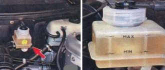
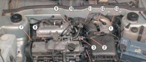
General view of the brake master cylinder (MBC) under the hood of a car with a fluid reservoir and a vacuum booster.
The master brake cylinder creates pressure in the system, distributes it along the circuits and transmits it to the wheel cylinders. It consists of a two-section housing, inside which a piston moves, driven by a pedal. The fluid pressure created in the hydraulic structure is transmitted through circuits to the wheel mechanisms.
The vacuum booster reduces the force applied to the pedal. This makes the system more efficient. The operation of the vacuum valve directly depends on the operation of the engine. The vacuum booster is connected to the engine intake manifold by a flexible rubber hose. The vacuum (vacuum) in the amplifier is created by creating low pressure in the intake manifold from the movement of the engine pistons during the intake stroke.
Repair manual for VAZ 2108, 2109, 2114, 2115
Valve body 21 is plastic. At the outlet of the cover, it is sealed with a corrugated protective cover 13. The valve body houses the main cylinder drive rod 1 with a support sleeve, rod buffer 20, valve body piston 12, valve assembly 18, pusher and valve return springs 16 and 17, air filter 14 , pusher 15.
When you press the pedal, the pusher 15, the piston 12, and after them the valve 18 move until it stops against the seat of the valve body. In this case, cameras A and B are separated. As the piston moves further, its seat moves away from the valve and through the resulting gap, chamber B is connected to the atmosphere. The air entering through filter 14 into the gap between the piston and the valve and channel D creates pressure on the diaphragm 10. Due to the difference in pressure in chambers A and B, the valve body moves along with rod 1, which acts on the piston of the master cylinder.
It will be useful: Instrument cluster Lada Priora with navigation: instructions
When the pedal is released, the valve moves away from its body and through the resulting gap and channel C of chambers A and B communicate with each other.
The pressure regulator regulates the pressure in the hydraulic drive of the rear wheel brakes depending on the load on the rear axle of the vehicle. It is included in both circuits of the brake system and through it brake fluid flows to both rear brake mechanisms.
Rice. 6.3. Pressure regulator drive: 1 – pressure regulator; 2, 16 – pressure regulator mounting bolts; 3 – bracket for the pressure regulator drive lever; 4 – pin; 5 – pressure regulator drive lever; 6 – axis of the pressure regulator drive lever; 7 – lever spring; 8 – body bracket; 9 – pressure regulator mounting bracket; 10 – elastic lever of the pressure regulator drive; 11 – earring; 12 – earring bracket; 13 – washer; 14 – retaining ring; 15 – bracket finger; A, B, C – holes
Pressure regulator 1 (Fig. 6.3) is attached to bracket 9 with two bolts 2 and 16. At the same time, front bolt 2 simultaneously secures fork bracket 3 of lever 5 of the pressure regulator drive. A double-arm lever 5 is hinged on the pin of this bracket with a pin 4. Its upper arm is connected to an elastic lever 10, the other end of which is pivotally connected to the rear suspension arm bracket through an earring 11.
Bracket 3 together with lever 5 can be moved relative to the pressure regulator due to the oval holes for the fastening bolt. This regulates the force with which lever 5 acts on the regulator piston (see “Adjusting the pressure regulator drive”).
Rice. 6.4. Pressure regulator: 1 – pressure regulator housing; 2 – piston; 3 – protective cap;
4, 8 – retaining rings; 5 – piston sleeve; 6 – piston spring; 7 – body bushing; 9, 22 – support washers; 10 – sealing rings of the pusher; 11 – support plate; 12 – pusher bushing spring; 13 – valve seat sealing ring; 14 – valve seat; 15 – sealing gasket; 16 – plug; 17 – valve spring; 18 – valve; 19 – pusher bushing; 20 – pusher; 21 – piston head seal; 23 – piston rod seal; 24 – plug; A, D – chambers connected to the main cylinder; B, C – chambers connected to the wheel cylinders of the rear brakes; K, M, N – gaps
The regulator has four chambers: A and D (Fig. 6.4) are connected to the main cylinder, B - to the right, and C - to the left wheel cylinders of the rear brakes.
In the initial position of the brake pedal, piston 2 (see Fig. 6.4) is pressed by lever 5 (see Fig. 6.3) through leaf spring 7 to pusher 20 (see Fig. 6.4), which under this force is pressed against seat 14 of valve 18. In this case, valve 18 is pressed away from the seat and a gap H is formed, as well as a gap K between the piston head and seal 21. Through these gaps, chambers A and D communicate with chambers B and C.
When you press the brake pedal, fluid flows through gaps K and H and chambers B and C into the wheel cylinders of the brake mechanisms. As the fluid pressure increases, the force on the piston increases, tending to push it out of the housing. When the force from the liquid pressure exceeds the force from the elastic lever, the piston begins to move out of the body, and after it, under the action of springs 12 and 17, the pusher 20 moves together with the sleeve 19 and rings 10. In this case, the gap M increases, and the gaps H and K decrease . When the gap H is completely selected and the valve 18 isolates chamber D from chamber C, the pusher 20, together with the parts located on it, stops moving after the piston. Now the pressure in chamber C will vary depending on the pressure in chamber B. With a further increase in the force on the brake pedal, the pressure in chambers D, B and A increases, piston 2 continues to move out of the body, and sleeve 19 together with o-rings 10 and plate 11 under increasing pressure in chamber B, it shifts towards plug 16. At the same time, the gap M begins to decrease. Due to the decrease in the volume of chamber C, the pressure in it, and therefore in the brake drive, increases and will be practically equal to the pressure in chamber B. When the gap K becomes zero, the pressure in chamber B, and therefore in chamber C, will increase to a lesser extent degree than the pressure in chamber A due to throttling of the liquid between the piston head and seal 21. The relationship between the pressure in chambers B and A is determined by the ratio of the difference in the areas of the head and piston rod to the area of the head.
As the vehicle load increases, the elastic lever 10 (see Fig. 6.3) is loaded more and the force from the lever 5 on the piston increases, that is, the moment of contact between the piston head and the seal 21 (see Fig. 6.4) is achieved at greater pressure in the main brake cylinder. Thus, the effectiveness of the rear brakes increases with increasing load.
If the brake circuit “right front - left rear brake” fails, the O-rings 10, bushing 19, under the pressure of the liquid in chamber B, will move towards the plug 16 until the plate 11 stops in the seat 14. The pressure in the rear brake will be regulated by the part of the regulator, which includes piston 2 with seal 21 and bushing 7. The operation of this part of the regulator, in the event of a failure of the said circuit, is similar to the operation with a working system. The nature of the change in pressure at the outlet of the regulator is the same as with a working system.
If the brake circuit “left front - right rear brake” fails, the pressure of the brake fluid forces the pusher 20 with the bushing 19 and sealing rings 10 towards the piston, pushing it out of the housing. The M gap increases and the H gap decreases. When valve 18 touches seat 14, the increase in pressure in chamber C stops, that is, the regulator in this case works as a pressure limiter. However, the achieved pressure is sufficient for reliable operation of the rear brake.
There is a hole in housing 1, closed by plug 24. Liquid leakage from under the plug when it is squeezed out indicates a leak in rings 10.
Rice. 6.5. Main cylinder with reservoir: 1 – main cylinder body; 2 – low pressure sealing ring; 3 – drive piston of the “left front-right rear brake” circuit; 4 – spacer ring; 5 – high pressure sealing ring; 6 – pressure spring of the sealing ring; 7 – spring plate; 8 – piston return spring; 9 – washer; 10 – locking screw; 11 – drive piston of the “right front-left rear brake” circuit; 12 – connecting sleeve; 13 – tank; 14 – brake fluid emergency level sensor; A – gap
Rice. 6.6. Front wheel brake mechanism: 1 – brake disc; 2 – pad guide; 3 – caliper; 4 – brake pads; 5 – cylinder; 6 – piston; 7 – sealing ring; 8 – protective cover of the guide pin; 9 – guide pin; 10 – protective casing
A piston 6 with a sealing ring 7 is installed in the cavity of the cylinder 5. Due to the elasticity of this ring, the optimal gap between the pads and the disk is maintained.
In a variant, cars are equipped with pads with a pad wear indicator.
It will be useful: Tuning the interior of a VAZ 2109 with your own hands: video instructions
Rice. 6.7. Rear wheel brake mechanism: 1 – hub fastening nut; 2 – wheel hub; 3 – lower tension spring of the pads; 4 – brake pad; 5 – guide spring; 6 – wheel cylinder; 7 – upper tension spring; 8 – expansion bar; 9 – finger of the parking brake drive lever; 10 – parking brake drive lever; 11 – brake shield
Rice. 6.8. Wheel cylinder: 1 – pad stop; 2 – protective cap; 3 – cylinder body; 4 – piston; 5 – seal; 6 – support plate; 7 – spring; 8 – crackers; 9 – thrust ring; 10 – thrust screw; 11 – fitting; A – slot on the thrust ring
The thrust rings 9 are inserted into the cylinder with tension, providing a shear force of the ring along the cylinder mirror of at least 343 N (35 kgf), which exceeds the force on the piston from tension springs 3 and 7 (see Fig. 6.7) of the brake pads.
When, due to wear of the linings, the gap of 1.25–1.65 mm is completely removed, the shoulder on the thrust screw 10 (see Fig. 6.8) is pressed against the shoulder of the ring 9, as a result of which the thrust ring moves after the piston by the amount of wear. When the braking stops, the pistons are moved by the force of the tension springs until the cracks stop against the shoulder of the thrust ring. This automatically maintains the optimal clearance between the pads and the drum.
Rice. 6.9. Parking brake system drive: 1 – lever fixation button; 2 – parking brake drive lever; 3 – protective cover; 4 – traction; 5 – cable equalizer; 6 – adjusting nut; 7 – lock nut; 8 – cable; 9 – cable sheath
Rice. 6.10. Emergency brake fluid level sensor: 1 – protective cap; 2 – sensor housing; 3 – sensor base; 4 – sealing ring; 5 – clamping ring; 6 – reflector; 7 – pusher; 8 – bushing; 9 – float; 10 – fixed contacts; 11 – moving contact
Mechanical brake fluid emergency level sensor. Housing 2 (Fig. 6.10) of the sensor with seal 4 is pressed to base 3 by clamping ring 5, which is screwed onto the neck of the tank. At the same time, the reflector flange 6 is pressed against the end of the neck. In this position, the clamping ring is held by two clamps made on the base 3.
A pusher 7 passes through the hole in the base, connected to the float 9 using a bushing 8. There is a movable contact 11 on the pusher, and fixed contacts 10 are located on the sensor body. The contact cavity is sealed with a protective cap 1.
When the level of brake fluid in the reservoir drops to the maximum permissible level, the moving contact moves down onto the fixed contacts and closes the circuit of the hazard warning lamp on the instrument panel.
Tuesday, April 13, 2010
VAZ-2114, VAZ-2115 – braking system, features, troubleshooting
The VAZ-2115 is equipped with a brake system with diagonally divided circuits, which significantly increases braking efficiency. The 1st circuit is responsible for the right front and left rear brake mechanisms. The 2nd circuit is responsible for the left front and right rear brake mechanisms.
1.Front wheel brake mechanism 2.Left front-right rear
3. Main cylinder of the hydraulic brake drive 4.
Right front-left rear
pipeline 5. Master cylinder reservoir 6. Vacuum booster 7. Rear wheel brake mechanism 8. Elastic pressure regulator drive lever 9. Pressure regulator 10. Pressure regulator drive lever 11. Pedal brakes A.Front brake hose B.Rear brake hose
If one of the circuits fails, the second circuit is used for braking, which allows you to brake effectively even if there is a malfunction in the braking system.
The hydraulic drive includes a vacuum booster and a dual-circuit pressure regulator for the rear brakes.
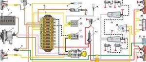
1. Rod 2. Master cylinder flange O-ring 3. Booster housing cup 4. Adjusting bolt 5. Rod seal 6. Diaphragm return spring 7. Booster pin 8. Sealing boot 9. Booster housing 10. Diaphragm 11. Booster housing cover 12. Piston 13.Valve body protective boot 14.Air filter 15.Pushrod 16.Pushrod return spring 17.Valve spring 18.Valve 19.Valve body bushing 20.Rod buffer 21.Valve body; A-vacuum chamber; B-atmospheric chamber; C, D channels.
Rubber diaphragm 10 (Fig. 2), together with valve body 21, divides the vacuum booster cavity into two chambers: vacuum A and atmospheric B. Chamber A is connected to the engine intake pipe. Valve body 21 is plastic. At the outlet of the cover, it is sealed with a corrugated protective cover 13. The valve body houses the main cylinder drive rod 1 with a support sleeve, rod buffer 20, valve body piston 12, valve assembly 18, pusher and valve return springs 16 and 17, air filter 14 , pusher 15. When you press the pedal, pusher 15, piston 12, and after them valve 18 move until they stop against the seat of the valve body. In this case, cameras A and B are separated. As the piston moves further, its seat moves away from the valve and through the resulting gap, chamber B is connected to the atmosphere. The air entering through filter 14, the gap between the piston and the valve and channel D creates pressure on the diaphragm 10. Due to the difference in pressure in chambers A and B, the valve body moves along with rod 1, which acts on the piston of the main cylinder. When the pedal is released, the valve moves away from its body and through the resulting gap and channel C of chambers A and B communicate with each other.
Device
The VAZ-2115 uses a brake system in which the operating circuits are divided diagonally. This can significantly increase the degree of reliability and safety of people. In particular, the first of them controls the operation of the front right and rear left brake mechanisms. If it fails, the second circuit is switched on.
In addition, the hydraulic drive operating diagram also includes:
- vacuum booster;
- a dual-circuit regulator whose task is to maintain pressure in the brakes located behind.
A sensor is installed on the VAZ-2115 that signals a decrease in brake fluid volumes. It's mechanical. In addition, there is also a parking brake system, which, in turn, has a separate drive that blocks the rear axle if necessary.
As can be understood from the diagram, the system in question is quite complex, and from time to time certain breakdowns occur in it.
To understand what kind of problem arose at one time or another requires quite a lot of experience. However, it is not difficult to make the diagnosis yourself if you use the recommendations below.
The brake pedal has too much travel
In this case, one might suspect that:
- air has entered the hydraulic drive;
- the rear cylinder piston thrust ring lost elasticity, as a result of which it shifted inward;
- Brake fluid has leaked from the system;
- There is too much clearance between the main cylinder piston and the vacuum booster adjusting bolt.
- in the first case, you will need to bleed the system;
- in the 2nd - you will need to completely change the cylinder;
- in the 3rd - eliminate the leak by replacing seals or hoses that have become unusable.
Brake performance is low
The most common reasons for this problem are:
- brake pads are oily;
- pistons jam in wheel cylinders;
- the linings on the blocks have become unusable;
- the brake system mechanisms overheated;
- the pressure regulator was set incorrectly;
- one of the circuits has lost its tightness.
The linings on the brake pads will need to be cleaned using a wire brush, warm water and washing powder.
If the pistons jam, you will have to change the cylinders and bleed the system.
When the linings wear out, they need to be removed and new ones installed.
Overheating of the system is eliminated by immediate shutdown. It will take some time for it to cool completely.
Why the wheel mechanisms are not fully released
Most likely, this malfunction will cause the brake pedal to stick. In this case, you will have to adjust it.
In addition, the disappearance of the gap between the piston in the master cylinder and the vacuum booster adjustment bolt may also be the cause. The problem is eliminated by increasing the lumen.
If fuel or oil gets into the brake fluid, the gaskets in the master cylinder sometimes swell. You will need to flush the entire system with new brake fluid and replace seals that have become unusable.
Braking of one of the wheels is observed when driving
Most often, such a breakdown is caused by the destruction of the tension spring on the rear brake. The damaged one will have to be removed and a new one put in its place.
It is also common for pistons in wheel cylinders to not function properly if dirt has gotten inside or they have begun to rust. Cleaning and rinsing will eliminate the problem.
Sometimes braking occurs due to loosening of the bolts that secure the guide pads directly to the steering knuckle. If they are re-tightened or replaced with new ones, the problem will be eliminated.
And finally, this can happen because the parking brake system has not been adjusted correctly.
Error P0504 or problem with the brake pedal sensor
Blog
@belais11051
Hello everyone! I would like to tell you a little about the M74 ECU and the common error “P0504 Incorrect signal from the brake pedal switches.” In connection with the transition to new toxicity standards, AVTOVAZ engineers and designers have developed a new line of M74 and M17.9.7 ECUs. The ECUs can be said to be normal, but have not yet been fully tested. After all, cars on these ECUs are very much “strangled” by toxicity standards and therefore, without reprog and installing firmware e2 or lower, you can’t drive the car in any way, but this action is not all available now, since the protocol, pads and the reprog algorithm itself have changed with the ECU, in Therefore, it is necessary to have an additional module for the programmer. Diagnostics of ECU data is already available, since all major companies have taken care of their customers and have released software updates.
Well, okay, I’ll start right away with the story of how to get rid of the error “P0504 Incorrect signal from the brake pedal switches.” Due to the fact that the ECUs were changed, AVTOVAZ began installing new sensors and IMs. There are also 2 new sensors on the brake pedal, just don’t be alarmed if you suddenly find only one. AVTOVAZ designers and engineers managed to combine 2 sensors in 1 housing, that is, only one sensor is installed on the brake pedal, but this is not so, inside the housing there is the brake pedal sensor itself and another sensor, which is popularly called “frog”. Error “P0504 Incorrect signal from the brake pedal switches” appears because the sensors are not adjusted properly from the factory. If suddenly a car with M74 or M17.9.7 came to you and the scanner produced such an error, then you can safely take the keys and adjust the sensor gap, since it is not adjusted. The sensor is adjusted in a simple way and is not difficult. There are two nuts on the sensor body. One secures the sensor to the mount from above, and the other from below. The nut that is on top regulates the sensor gap, so loosen the bottom nut a little, and then tighten the top one a little, thereby adjusting the sensor gap. In my case, the sensor was set from the factory so that the button was pressed only halfway, now I made it press almost completely. I say almost due to the fact that I left a small reserve of travel for the button, about 2 mm, so that when the brake pedal is suddenly released, the button does not get too clogged into the sensor. When you adjust the gap, then start the car, having first reset the error, and let it run for a while, since the error is not registered immediately, but after a certain period of 5-10 minutes. If the error is not registered, then you can safely take money from the client and say goodbye to him. Also, on some cars, a clutch pedal sensor is installed; it also needs adjustment, because if it is not adjusted, the car begins to stall, as it were, since the ECU thinks that the clutch pedal is depressed. I guess I'll finish here. If new information appears on the ECU data, I will post it on this forum, since it is the best.
This error often occurs on new cars, since in my opinion our cars are made through... and there is no good quality control department, since cars with such bugs are passed through.
The article is not mine. Many thanks to: DimkaTitov (DRIVE2).
September 13, 2014 — 12522 views Comments
The car skids or pulls to the side when you press the brakes
Most often this happens if the piston in the wheel cylinder is jammed. It will need to be disassembled and cleaned. All detected damaged elements must be replaced with new ones.
In some cases, the problem also occurs if one of the metal pipes in the brake system has been broken or clogged.
Similarly, skidding when braking is caused by oil getting on the following parts of the system: discs, linings, drums. In this case, they need degreasing.
In addition, this may indicate a breakdown of the pressure regulator - repair of this part is not provided, so it is simply replaced with a new one.
And finally, the car skids when braking due to:
- incorrect wheel angles;
- low pressure in one of the tires;
- failure of any of the brake circuits.
How to replace the pads on a VAZ-2115 is described in detail in this video:
How does the brake system pressure regulator work?
17.07.2012
Its main function is to regulate the pressure in the hydraulic drive depending on the load on the rear of the vehicle.
With the help of a pressure regulator, brake fluid flows to the rear brake mechanisms.
Pressure regulator drive
The pressure regulator (numbered 1 in the picture) is attached to the bracket (numbered 9) with two bolts (numbered 2 and 16). In this case, the first bolt holds the fork bracket (number 3) and attaches it to the pressure regulator drive lever (number 5).
A two-arm lever (number 5) is also attached to part of the bracket with a pin (number 4). The upper arm of the bracket is connected to an elastic lever (numbered 10), which is pivotally connected to the rear suspension arm bracket through an earring (numbered 11).
Pressure regulator
The regulator has four chambers: D and A (in the diagram), which are connected to the main cylinder, C to the left, and B to the right wheel cylinders.
When you press the brake pedal, fluid enters the wheel cylinders through chambers B and C, gaps H and K. When the fluid pressure increases, the force on the piston increases, which tends to push it outside the housing. If the force from the brake fluid pressure exceeds the force from the lever, then a pusher (number 20) with rings (number 10) and a bushing (number 19) will begin to move after the piston under the influence of springs (numbers 12 and 17). During this, the gap (in diagram M) will increase, and the gaps (in diagram M and K) will, on the contrary, decrease.
When the gap (in diagram H) is completely selected, and the valve (numbered 18) isolates the chambers (in diagram D and C) from each other, then the pusher (numbered 20) with all its parts will stop moving behind the piston.
When the vehicle load increases, the elastic lever (number 10) is loaded even more, and the force from the lever on the piston (number 5) also increases, in other words, the contact of the seal (number 21) and the piston head is achieved in the master cylinder at high pressure. Consequently, as this load increases, the efficiency of the rear brakes also increases.
There is a hole in the pressure regulator housing (number 1) that is closed with a plug (number 24). If liquid leaks out from under the plug, this will accordingly indicate that the rings used are not tight (number 10).
Brake system VAZ 2115
Safety when driving a car is ensured by several systems, however, the main role is still assigned to the car's brake system. Timely braking saves you from traffic accidents, and the hand (parking) brake helps to secure the car on an inclined surface. It is these elements of the car that need to be given special attention. Timely diagnostics and repairs will help protect you and your car.
Malfunctions
Possible malfunctions of the brake system and methods for eliminating them are given in the table:
It will be useful: Tuning Lada Granta sedan: photo and video review
Increased brake pedal travel
Leakage of brake fluid from wheel cylinders
Replace failed parts of wheel cylinders, wash and dry pads, discs and drums, bleed the hydraulic drive system
Air in the brake system
Remove air from the system
Damaged rubber o-rings in the master cylinder
Replace the rings and bleed the system
Damaged rubber hoses for hydraulic brakes
Replace the hoses and bleed the system
Increased runout of the brake disc (more than 0.15 mm)
Sand the disc; If the disc thickness is less than 17.8 mm, the brake disc should be replaced
Fluid leakage through the pressure regulator pusher O-rings
Replace O-rings
Insufficient braking performance
Oiling of brake pad linings
Wash and dry the pads
Piston jamming in wheel cylinders
Eliminate the causes of jamming, replace damaged parts, bleed the system
Complete wear of the brake pads
Replace the brake pads
Overheating of brake mechanisms
Stop immediately and let the brakes cool down.
Using pads with mismatched linings
Use only pads recommended by the manufacturer
Incorrect pressure regulator adjustment
Adjust the pressure regulator drive
Loss of tightness of one of the circuits (accompanied by partial failure of the brake pedal)
Replace damaged parts, bleed the system
Incomplete release of all wheels
There is no free play in the brake pedal
Adjust pedal free play
The protrusion of the adjusting bolt of the vacuum booster rod relative to the mounting plane of the master cylinder is impaired
Adjust the protrusion of the 1.25-0.2mm adjusting bolt
Swelling of the rubber seals of the master cylinder due to gasoline, mineral oils, etc. getting into the liquid.
Thoroughly flush the entire system with brake fluid, replace rubber parts, bleed the hydraulic drive system
Master cylinder piston jamming
Check and, if necessary, replace the master cylinder, bleed the system
Leveling up
If you have done all of the above, then it is time to move on to the main work. By adding oil and dealing with the rear brake problem, you have only prepared your VAZ 2115 for bleeding.
After this, the entire brake system must be thoroughly cleaned. The most important thing is that the air release valve is in perfect condition, otherwise it will not be possible to bleed the brake system. In any case, it can be replaced, but it will take a lot of time. If everything is in order with the car, then feel free to remove the protective cap from the valve.
Now you need to insert one end of the hose into the valve, and place the other in a container with brake fluid. The most important thing is that the end of the hose is accurately immersed in the brake fluid, and not just hanging on it. After this, you just need an assistant. His task will be to press the brake pedal.
You need to do this about five times, and then hold the pedal down constantly.
In general, the procedure for releasing air must be carried out several times until there is no air left in the valve. At this moment, monitor the amount of oil in the tank, since its level should not be below about. Bleeding the brakes on a VAZ 2115 is not that difficult if you work in pairs, so be sure to call someone for help. When the brakes are bled, check how they work on the other wheels and, if necessary, carry out exactly the same operation with them.
Brake system VAZ 2114 diagram photo
8.1. Hydraulic brake circuit diagram:
A – flexible hose of the front brake; B – flexible hose of the rear brake; 1 – front wheel brake mechanism; 2 – left front–right rear brake circuit pipeline; 3 – main cylinder for hydraulic brakes; 4 – pipeline of the right front–left rear brake circuit; 5 – master cylinder reservoir; 6 – vacuum booster; 7 – rear wheel brake mechanism; 8 – elastic lever of the pressure regulator drive; 9 – pressure regulator; 10 – pressure regulator drive lever; 11 – brake pedal
The car uses a working brake system with diagonally separated circuits (Fig. 8.1), which significantly increases the safety of driving the car. One hydraulic drive circuit ensures the operation of the right front and left rear brake mechanisms, the other - the left front and right rear. If one of the circuits of the service brake system fails, the second circuit is used to stop the vehicle with sufficient efficiency.
The hydraulic drive includes a vacuum booster 6 and a dual-circuit pressure regulator 9 in the rear brakes.
The parking brake system is driven by the brake mechanisms of the rear wheels.
8.6. Front wheel brake:
1 – brake disc; 2 – pad guide; 3 – caliper; 4 – brake pads; 5 – working cylinder; 6 – piston; 7 – sealing ring; 8 – protective cover of the guide pin; 9 – guide pin; 10 – protective casing
Front wheel brake
disc, with automatic adjustment of the gap between the pads and the disc, with a floating bracket.
The bracket is formed by caliper 3 (Fig. 8.6) and working cylinder 5, tightened with bolts. The movable bracket is bolted to pins 9 installed in the holes of the shoe guide. Lubricant is placed in these holes, rubber covers 8 are installed between the pins and the pad guide. The brake pads 4 are pressed against the grooves of the guide by springs.
A piston 6 with a sealing ring 7 is installed in the cavity of the cylinder 5. Due to the elasticity of this ring, the optimal gap between the brake pads and the disc is maintained. In a variant, cars can be equipped with pads with a pad lining wear indicator.
8.7. Rear wheel brake:
1 – hub fastening nut; 2 – wheel hub; 3 – lower tension spring of the pads; 4 – brake pad; 5 – guide spring; 6 – working cylinder; 7 – upper tension spring; 8 – expansion bar; 9 – finger of the parking brake drive lever; 10 – parking brake drive lever; 11 – brake shield
8.8. Rear wheel brake working cylinder:
A – slot on the thrust ring; 1 – block stop; 2 – protective cap; 3 – cylinder body; 4 – piston; 5 – seal; 6 – support plate; 7 – spring; 8 – crackers; 9 – thrust ring; 10 – thrust screw; 11 – fitting
Rear wheel brake
(Fig. 8.7) drum, with automatic adjustment of the gap between the shoes and the drum. The automatic clearance adjustment device is located in the working cylinder. Its main element is a split thrust ring 9 (Fig. 8.8), installed on the piston 4 between the shoulder of the thrust screw 10 and two nuts 8 with a gap of 1.25–1.65 mm.
The thrust rings 9 are inserted into the cylinder with tension, providing a shear force of the ring along the cylinder mirror of at least 343 N (35 kgf), which exceeds the force on the piston from tension springs 3 and 7 (see Fig. 8.7) of the brake pads.
When, due to wear of the linings, the gap of 1.25–1.65 mm is completely selected, the shoulder on the thrust screw 10 (see Fig. 8.8) is pressed against the shoulder of the ring 9, as a result of which the thrust ring moves after the piston by the amount of wear. When the braking stops, the pistons are moved by the force of the tension springs until the cracks stop against the shoulder of the thrust ring. This automatically maintains the optimal gap between the pads and the drum.
8.9. Parking brake system drive:
1 – lever fixation button; 2 – parking brake drive lever; 3 – protective cover; 4 – traction; 5 – cable equalizer; 6 – adjusting nut; 7 – lock nut; 8 – cable; 9 – cable sheath
Parking brake system
with a mechanical drive, acts on the brake mechanisms of the rear wheels. The parking brake drive consists of lever 2 (Fig. 8.9), adjusting rod 4, equalizer 5, cable 8, lever 10 (see Fig. 8.7), manual pad drive and expansion bar 8.
8.10. Emergency brake fluid level sensor:
1 – protective cap; 2 – sensor housing; 3 – sensor base; 4 – sealing ring; 5 – clamping ring; 6 – reflector; 7 – pusher; 8 – bushing; 9 – float; 10 – fixed contacts; 11 – moving contact
Emergency brake fluid level sensor
mechanical type.
Housing 2 (Fig. 8.10) of the sensor with seal 4 is pressed to base 3 by clamping ring 5 screwed onto the neck of the tank. At the same time, the reflector flange 6 is pressed against the end of the neck. In this position, the clamping ring is held by two clamps made on the base 3.
A pusher 7 passes through the base hole, connected to the float 9 using a bushing 8. There is a movable contact 11 on the pusher, and fixed contacts 10 are located on the sensor body. The contact cavity is sealed with a protective cap 1.
When the level of brake fluid in the reservoir drops to the maximum permissible level, the moving contact moves down onto the fixed contacts and closes the circuit of the brake system emergency warning lamp in the instrument cluster.
Useful tips: There are two ways to bleed the brakes without an assistant.
- The first is the most reliable: order a turner an aluminum or bronze cover for the main brake cylinder, screw the valve from the brake chamber into it and connect it to the spare wheel with an additional hose; air pressure should not exceed 0.05–0.07 MPa (0.5–0.7 kgf/cm2).
- The second is not very reliable, but acceptable: connect the rubber bulb to the wheel cylinder fitting - the connection should be very tight. Squeeze the bulb, unscrew the fitting; When the bulb is half full, tighten the fitting. Repeat the procedure 3-4 times. During test braking, check the operation of the brakes.