People have long lived surrounded by electrical appliances, which have quietly entered the life of every person since childhood. Electronic watches, electric kettles, telephones, computers, cars are indispensable human assistants in everyday life and at work. But sometimes devices break down and you have to check and repair them. There is nothing difficult about this if you know how to use measuring instruments and know, for example, how to test the wiring in a car with a multimeter or how to check the integrity of an electrical circuit.
General information
You don't need to be a professional electrician to find a wire break. It is enough to have a measuring device - a multimeter . A multimeter is a multifunctional measuring instrument with its own voltage source. The device can measure the voltage in the circuit, the magnitude of the current and the resistance value. Many multimeters are used to test the continuity of a connection in a circuit.
If a connection is found, then if there is a built-in speaker, the device emits a sound signal. This is where the term “call” comes from. The device rings if there is a connection. A multimeter can also indicate that there is no connection between elements and helps determine a short circuit. Using the tester, all kinds of radio components are checked: resistors, transistors, diodes, relays, capacitors, and so on.
Conductor continuity is based on Ohm's law for a section of an electrical circuit. Ohm's law states that the resistance of an element is equal to the ratio of the applied voltage to the magnitude of the current in a section of the electrical network. Resistance is measured in Ohms. A resistance of one Ohm indicates that a current equal to one Ampere flows through the conductor at a given voltage of one Volt. Based on the calculated data on resistance, conclusions are drawn about the results of the call.
That is, a certain voltage is set on the multimeter, and the current value is determined using the instrument scale and the resistance is calculated. In other words, the multimeter is a voltage source and an ammeter to measure the resulting current.
Checking the electrical wiring
If everything is very simple with fuses and it is enough to install a new one instead of a burnt one, then with electrical wiring everything is much more complicated. The main sign of a short circuit in a car is a re-blown fuse that has just been replaced. Therefore, the reason must be looked for in the wiring, using the exclusion method.
Read more: How to make negative camber of the rear wheels
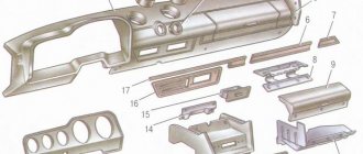
In this case, different consumers are alternately disconnected from the line being tested. At the same time, the integrity of the wires is checked. Often the location of an accident is determined visually, based on traces of burnt and melted insulation. However, some wires are hidden too far, for example under the instrument panel, so priority testing is given to consumers.
Searches must be performed in a certain order, with the voltage turned on. But this operation will not be possible in the presence of a short circuit, since the fuse immediately burns out. Therefore, instead of a fuse, a high-power consumer is used, for example, a 55 W lamp. Wires are connected to its terminals using terminals. The other ends of the conductors are connected instead of the fuse, also using terminals. The light bulb is connected in series so that current passes through it, and it itself is located within line of sight.
If there is a short circuit in the car wiring line being tested, then when turned on, the light bulb will light up brightly at full power. When it is connected to a working line, the glow will be dim, since the current in this section has a nominal value. This way, using the elimination method, you can find out the state of all consumers one by one.
When a faulty consumer being tested is detected, you can try to repair it. However, experts recommend not to take risks and install a new part. You should not joke with a short circuit, because in another case, under an unfortunate set of circumstances, all the wiring and even the car itself may burn out.
Sometimes a situation may arise when all consumers have already been checked, but the light bulb still shines at full power, that is, the reason has not yet been found. This indicates a short circuit in the wiring itself, and not in the consumers. In this case, the check becomes significantly more complicated, since to access all lines you will have to dismantle interior elements and other parts.
However, with a tester, if available, you can check areas that are freely accessible and significantly reduce your searches. These tasks are more complex and require the intervention of qualified automotive electricians. In addition, the driver will need knowledge and skills in disassembling and assembling various elements of the car, rules for using ordinary and special tools.
The electrical network (wiring) of modern cars is single-wire, the second conductor is “ground” - the car body and the engine. During the operation of the vehicle, you may encounter some wiring faults (for example, a short circuit or break). Next, let's look at the instructions on how to find them yourself.
All electrical circuits (except for the starter and generator power circuits) are protected by fuses. And the power circuits of powerful electricity consumers (headlights, power windows, heated mirrors or seats, etc.) are switched through a relay. Therefore, you should start troubleshooting the electrical wiring in the following sequence:
- if a lighting device does not work (for example, a headlight or a lampshade), then first we check whether the lamp has burned out;
- check the serviceability of the fuse;
- check the serviceability of the relay;
- check the reliability of the contacts in the circuit connectors (they may oxidize, in which case they need to be cleaned).
Read more: Brake caliper tightening torque
It is also recommended to check all ground attachment points.
Relay and fuse diagrams for LADA cars:
Device structure
Devices may differ in appearance, but multimeters are fundamentally divided into analog devices and digital devices.
Analogue devices are already gradually being replaced from the market by digital ones, but in the homes of many home craftsmen you can still find analog devices.
Such devices are equipped with an indicator screen with a scale and arrow. The advantage of these models is the clarity of display of measurements. The deflection of the needle is visually easier to assess than the flashing of numbers on the electronic display of digital instruments. Often, when making a call, it is necessary to evaluate approximate resistance indicators or, in general, its presence or presence, so analog devices are suitable for most practical work.
Digital multimeters have more complex electronics and a digital display. This type of device is used mainly in production and industry.
The housings of all multimeters have outputs for two probes. These are two insulated wires ending in needle-like metal tips. In some cases, special clips, so-called “crocodiles,” are put on the nozzles. When choosing a device, you need to pay special attention to the quality of the probes. The correctness of measurements depends on them.
The wires must be flexible with strong soldering and fit well into the device sockets. It often happens that outwardly spectacular probes are of unsatisfactory quality and have poor technical characteristics.
Operating principle
The analog type of the device does not require its own power supply . Its operating principle is the same as that of an ammeter, and an analog device works best in the range of radio waves and electromagnetic fields. There are induction coils inside the device body, and when the probes touch the conductor, a current begins to form in the coils. The created magnetic field deflects the indicator needle to a certain angle. The magnitude of this angle depends on the strength of the current generated, and the arrow on the drawn scale indicates the measurement value.
Digital devices contain a textolite printed circuit board on which a digital chip , which is responsible for processing the received data. To operate the electrical circuit and screen, digital devices are powered by batteries or an external power source.
Digital multimeters have lower measurement uncertainty and are more accurate than their analog counterparts.
There is a switch on the front panel of the multimeter that selects the measurement mode. The switch sets the scale factor that determines the value on the device scale.
Analog instruments have two types of scale:
- Uniform display.
- Logarithmic exponents.
The uniform scale is very sensitive to overloads, so the switch is first set to a large scale factor value, which is gradually reduced. The logarithmic scale does not have this drawback and has a range of values from zero to infinity.
Thus, the main components of multimeters are:
- Display for showing measured values.
- Connectors for probes and probes themselves.
- Switch for different modes and ranges.
Troubleshooting in a car's electrical circuit
If some component in the car does not work, then first of all you need to check the electrical circuit. There are no particular differences between how to test different wires in different cars with a multimeter, except for the high-voltage cable.
First, make sure that there is voltage in the circuit of the non-working unit:
- The multimeter is configured with a switch to measure voltage.
- The multimeter probe is connected to the ground of the machine or to the minus of the battery. A feature of the power supply pair in a car is that the negative cable is either very short or absent altogether.
- The remaining probe touches the supply cable. The wire must be disconnected from the device terminal.
If the tester indicator shows the presence of voltage, it means the wire is intact. By analogy, all wires of the node are called. If the wire is damaged, the multimeter scale shows zero.
It must be taken into account that in some areas of the car voltage is supplied only when the ignition key is turned on.
When the voltage check is completed, the current value is checked. The device is switched to ammeter mode, the switch selects a measurement range of up to ten amperes. All vehicle devices must be turned off and the tester must be properly connected to the vehicle's electrical network. To do this, a multimeter is connected between the positive terminal of the battery and the unit being tested. The device screen should display the found current value; it should correspond to the consumption of constantly switched on devices of the machine. If the current value exceeds the norm, a conclusion is drawn about its leakage.
In this case, they begin checking devices that are not included in the standard equipment of the car, and places where wiring is part of moving mechanical components.
Experienced craftsmen identify areas with a drop in current, focusing on the readings of a multimeter with the fuses removed one by one. Then check for sparking at the contacts.
If a misbehaving wire is detected, it is ringed to check its integrity, and then its resistance is measured.
One of the answers to the question of how to test wires with a multimeter is to measure the resistance of each of the wires of the node. The rating is applied to the braid, and a tester is connected to the wire in ohmmeter mode. Typically, the range of resistance values for automotive wiring ranges from 3.5 to 9.9 kOhm. The difference between the measured element and the norm should not be more than four kiloohms.
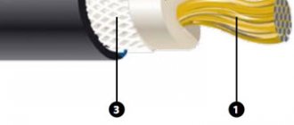
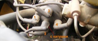
Checking the armored wire
The vehicle's power supply consists of the high-voltage wire of the ignition system. Before testing the power wire with a multimeter, carry out visual diagnostics with the motor running. When lighting candles, the voltage reaches several thousand volts.
Therefore, when high-voltage insulation breaks down, a spark occurs at a distance of three to five millimeters from the damaged area. In this case, if the insulation is damaged, sparking is accompanied by a breakdown to the engine, and the spark plug does not perform its function. If the diagnosis is carried out indoors or on a dark street, then the breakdown is clearly visible. The charge from the faulty area can heat the insulation until it ignites.
The cause of the malfunction may be damage to the contact assembly. In this case, the resistance of the central core increases. During corrosion due to thinning, some of the wires in the harness break, and the high resistance prevents the current from reaching the required level. Voltage, in turn, is not supplied to the electrodes of the spark plugs.
Testing a high-voltage cable is different from testing the wires with a multimeter, because the current in the cable is small. This is due to the very high voltage that passes through the power wire. Therefore, such wires have thick insulation and a small core diameter. In buzzer mode, the multimeter will not distinguish a intact wire from a damaged one.
In this case, the resistance is measured. To begin with, visually inspect the connection of the contact groups. According to statistics, breaks most often occur at contact points.
Then the contacts are cleaned with emery cloth to remove corrosion and the oxidative layer to avoid measurement errors. The multimeter is switched to resistance measurement mode with a measurement range of up to ten kOhms. Hands should not come into contact with wires and contacts. An intact armored train has a resistance from 3.5 kOhm to 10 kOhm. In any case, it is best to find the resistance data in the technical documentation and compare with the received ones. The difference should not be more than ten percent.
If you don’t have instructions at hand, then several wires ring in turn. The spread of resistance values of each element should not be more than two to three kilo-ohms.
Directly during measurement, when the cable is twisted, stretched or bent, the resistance should not “jump”.
Rules for using the dialer
The only rule that needs to be remembered is that the dialing process is allowed only in a completely de-energized circuit.
You may be interested in this Resistance check
Note! If you check live wires, you can get an electric shock and, in some cases, cause a fire.
Below we describe in detail how to check the wire with and without a multimeter.
How to properly test wires (with a multimeter and without instruments)
Step-by-step work process:
- before starting work, you must turn the multimeter handle to the desired position;
- connect the ends of the probes to the required sockets. The black probe goes into the socket marked COM (in some cases indicated as “*” or ground point), and the red one goes into the socket marked Ω (sometimes indicated as R). It must be emphasized that the symbol Ω can be drawn either alone or in combination with the designations of other signs (V, mA). This arrangement of wires will help maintain polarity when making future measurements;
How to connect probes
- turn on the multimeter. Basically, there is a separate button for this or work can start automatically when the handle is turned to the required position;
- close the measuring ends to each other. If a beep is heard, the device is working correctly;
- take the wire to be tested (strip it of insulation in advance). Touch the exposed parts of the cable with measuring probes;
- If it is working properly, a sound will sound and the multimeter readings will be zero or show resistance. If the screen shows 1 and there are no sounds, it means that the tested cable is broken.
You can ring the wires without using a multimeter. To work you will need:
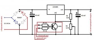
Diagram of a device with a light bulb
- a classic battery (it is advisable to take a 4.5-volt square battery);
- a regular 4-volt light bulb, through which the linear section of the cable is diagnosed (monitored);
- A pair of jumper cables and a breathtaking looking connector.
After preparing the tools for work, you need to use them to assemble a simple measuring circuit. If the circuit is correctly assembled and the wire is in good condition, the lamp will work. If there is a defect in the area, the light will not light up.
How to make a call with a multimeter
First, let's figure out what values the device measures. These are: current, voltage and resistance. At the moment we are interested in calling wires or cables using this device.
Before starting, you need to set the device to dialing mode. It is available on all devices with a special diode icon.
Then we need to check the functionality of our device. Connect the probes that come with the device to the required sockets. Shown in the picture below.
We close the probes together. You should hear a characteristic sound. This means that the electrical circuit is closed and there is no break between the probe wires.
The same can be done with the wire being tested for its integrity. If the wire being tested is long and laid somewhere, for example, in a wall, then you can use another auxiliary extension wire.
It is worth remembering that all actions to search for a wire break or its integrity must be carried out without supplying 220 V voltage to the wire being tested. Otherwise the device will fail.
How to ring a stranded wire or cable if its end is located at a great distance from its beginning?
The wires are stripped of insulation at both ends of the cable. Then check the wires for short circuits among themselves by touching each wire with the multimeter probes. If the device does not make a sound, then there is no short circuit.
After this, you can check the integrity of the wires in the cable. All the wires at one end of the cable are twisted together, and the wires at the other end are checked by touching the wires with probes. In this case, the device should produce a characteristic sound, which means the integrity of all wires in the cable.
If there is no sound when you touch any wire, then there is a break in the wire.
In the same way, you can call any wires in pairs, if required.
This kind of continuity is good when there are many wires of the same color and it is impossible to determine which wire goes where.
Continuity tester for electrical circuits
There is a wide variety of wire and cable testers on the market. The difference between a tester and a multimeter is that its functionality is more modest.
The main purpose is to connect wires and check voltage. Therefore, many types of testers are not only a continuity tester, but also a voltage indicator.
It is quite natural that each such device has batteries for indication and signal, which need to be replaced as time goes by.
You can make a simple dialer yourself at home. To do this, you need to take a 4.5 V battery, a 3.5 V light bulb and a piece of wire. The connection diagram is the simplest.
Setting up and preparing the multimeter
To use the multimeter correctly, you need to configure it. This means that you need to select the value to be measured and the limit of its operation, that is, the value beyond which it will not go.
Symbols on the front panel of the meter
A multimeter can be used to check various electrical quantities: current, voltage, resistance, frequency. It is also used to test the performance of various radio elements: resistors, capacitors, diodes and transistors. The very part of the word “multiple” implies the presence of several types of measurements. To select these types, there is a knob on the front panel of the tester, by turning which you can select the required value.
There is a higher class type of multimeter, for example, Agilent, in which the selection of measurement values is made not with a rotary knob, but with buttons. To select a value, simply click on the button corresponding to this value.
In most cases, the symbols depicted on the body of the multimeter represent designations of electrical quantities accepted in physics or conventional graphic designations of radioelements intended for testing . On the front panel you can find the following symbols:
- U - voltage symbol;
- V - stands for volts, this is also a measure of voltage;
- I is the current; when you set the knob to this designation, the current strength will be measured;
- A - amperes, a measure of current strength;
- Ω, R - symbol of resistance;
- Ohm is a measure of resistance, Ohms;
- -| |- - this icon indicates a capacitor, the multimeter will measure its capacitance;
- Diodes and transistors are also marked on the tester body with their symbols.
But not only the measured values are indicated on the front panel of the tester: the holes for connecting the probes also have their own designations. One of the meter slots will always be occupied by the black probe. This is a common hole, it is usually marked with the inscription COM, which means “common”. In addition to it, the multimeter has two or three working holes, designed respectively for measuring voltage, low current and high current.
The socket marked U, Ω, Hz is intended for measuring resistance, voltage and frequency, as well as for testing various radio elements. You also need to install a probe here to test wires and cables for breaks.
The hole marked mA (mA) is used to test low currents (up to 1 ampere), and the hole marked A (10 A) is needed to measure high amperages.
Also next to the voltage and current icons there are symbols
or -. This indicates the nature of the measured quantity: direct or alternating current or voltage.
Limits of measured values
In addition to designations of the values of the parameters being tested, designations of measurement limits are printed on the front panel of the multimeter. In more advanced equipment, these inscriptions are not present, since the tester electronics itself selects the limit based on the signal supplied to it at the input. However, most multimeters require manual adjustment of measurement limits.
Read also: How an impact wrench works
Typically, limits are given by numbers that are multiples of 2: 2, 20, 200... Thus, when choosing a limit, you should be guided by the rule: choose a limit higher than the one being measured, but of the same order. For example, to measure the voltage in a home electrical network (in an outlet), you need to select the AC voltage measurement mode and the measurement limit of 2000 volts. And to test the wires with a multimeter, you need to select the resistance mode and the minimum measurement limit of 2 ohms. However, long cables require a higher measurement limit of 20 ohms. Additionally, you can turn on the button with a sound signal that sounds when a short circuit occurs (circuit presence).
Connecting the tester
To check the parameters of electrical circuits and the continuity of wires and cables with a multimeter, you must correctly connect the meter to the circuit being tested. When checking for circuit integrity, the required area between the meter leads is checked. Therefore, the tester is connected to the terminals of the circuit. If voltage is being measured, the multimeter must be connected in parallel to the section where the voltage is being tested.
When measuring current, the multimeter must be connected in series to the open circuit of the circuit being tested, for example, between the power supply terminal and the load terminal.
Devices for troubleshooting electrical wiring
To find a short circuit or broken wiring, you can use a multimeter.
If you only need to determine the presence or absence of voltage on a section of the circuit, then you can use a special 12 V light indicator. A test lamp that you can make yourself is also suitable. To do this, two wires with a length of at least 50 cm should be soldered to a car lamp (no more than 4 W).
How to find a broken wiring in a car
If there is a break, the electrical circuit opens. Often the cause of lack of voltage is poor contact in the circuit connector. The block body hides oxidized contacts, so troubleshooting can take a long time. A break may be detected when the pads or wires are swayed.
To find a break in the test, you need to set the multimeter in ohmmeter or continuity mode. The terminals of the device are connected to the ends of the circuit being tested:
- If there is no break, the multimeter will beep (in dial mode) or the resistance will be minimal (in ohmmeter mode).
- If there is a break in the wiring, there will be no sound signal (in dial-up mode), but the resistance will be very high (in ohmmeter mode).
How to check wiring
You can diagnose electrical equipment using a voltmeter, ohmmeter or multimeter, or special diagnostic stands. Computer diagnostics are also carried out, during which error codes and main indicators of the machine’s on-board network are read. To independently check circuits and troubleshoot electrical faults, one multimeter or signal lamp is enough.
We use a multimeter
Fuses in the on-board network are considered the “weakest” link in terms of durability. In case of emergency situations (for example, in the event of a short circuit), the safety elements “take the blow”, protecting the rest of the electrics and electrical equipment of the machine. Fuses cannot be restored and must be replaced during repairs.
Checking the voltage
Before checking the wiring in the car, it is necessary to measure the voltage of the electrical circuit between individual components and electrical equipment. You can call like this:
- Set the multimeter to voltmeter mode.
- Connect one probe of the measuring device to the “minus” of the battery or to the ground of the machine.
- Connect the second probe to the supply wire of the circuit.
If a certain value appears on the device display, then there is voltage in this section of the electrical circuit. You can compare the values with those required according to the vehicle's owner's manual.
Looking for a short circuit
After measuring the voltage, search for short circuits. This will require either a multimeter or a pilot light. As for the lamp, if the wiring is in good condition and there is no short circuit, it should not light up.
A short circuit in the wiring, as well as a lack of voltage (zero or infinite resistance in the electrical circuit), indicates a malfunction in one of 2 components:
- Consumer - electrical equipment, devices, fuses, blocks.
- Wiring – broken or shorted wires, poor wiring contacts at the point of connection with the consumer.
Checking for a short circuit can also be done in voltmeter mode. To do this, it is necessary to remove all fuses in the area being tested and connect the probe to the terminals of the fuse element. The value “0” on the screen indicates the presence of a short circuit in the circuit. If, when you try to move the wires, voltage appears in the circuit, then the short circuit is caused by the wiring and the wires will need to be replaced.
Checking the quality of grounding
Cars use a single-wire wiring diagram - this means that the “minus” goes to the ground (body) of the car. However, corrosion of metal parts, their oxidation and destruction, “loosening” lead to grounding failure and, as a consequence, to disruption of on-board circuit contacts.
Checking the grounding, as well as other electrical elements of the car, is carried out using a multimeter. The procedure is as follows:
- Disconnecting the battery.
- Connecting one multimeter probe to the body (metal parts) of the car.
- Connecting the second probe to the grounding element or wiring connection.
Read also: How to properly connect a three-phase motor
The value displayed on the device screen should be compared with the factory data (car operating manual). If the values diverge greatly, then it is necessary to restore the grounding - clean the metal at the connection point, check the reliability of the fastening.
Checking the integrity of the circuit
The connection of wires in the electrical circuit of cars is one of the most vulnerable points in the entire electrical system of the car. In addition to the destruction of insulation, loss of integrity and breaks at the connection points, oxidation of the contacts also often occurs here. Defects can be determined not only using a measuring device, but also visually. If the integrity of the circuit is broken precisely at the connection point, then soldering of wires with connectors will be required. Otherwise, you need to find the damaged area, which will require a signal lamp or multimeter.
How to find a short circuit in a car wiring
A short circuit is an unacceptable connection of part of a circuit to ground or another part of the circuit. Often the cause of a short circuit is severe oxidation of the contacts in the block, or damage to the insulation of the wires. If, after replacing a faulty fuse, it blows again, there is likely a short circuit in the wiring.
To find a short circuit, disconnect the section of electrical wiring being tested from the rest of the vehicle wiring. Set the multimeter to dialing mode. We connect one probe of the device to a section of the circuit, and the other to the body (“ground”).
- If there is no short circuit in a section of the circuit, the device will not emit sound signals.
- If there is a short circuit, the multimeter will beep (the circuit will be closed).
We inspect the entire section of the chain for damage.
Let us remind you that it is more convenient to carry out wiring diagnostics when you have the car’s electrical circuit diagrams at hand (for Lada XRAY, Vesta, Largus, Granta, Kalina, Priora, Niva 4×4).
Key words: universal article
Causes of short circuit in automotive wiring
The main cause of any short circuit is damaged conductor insulation or faulty electrical consumers. In some cases, a short circuit occurs for reasons that the driver is not even aware of.
Modern cars have a large number of electrical appliances connected to the network. During operation, they gradually wear out, their contacts become deformed and break, their internal insulation melts, etc. If this happens, it is necessary to find the cause, that is, a faulty device that caused the short circuit. You will have to check all the components one by one, but first of all you should pay attention to obvious signs of malfunction.
A short circuit in a car that occurs due to broken insulation is primarily due to improper routing of wires. The harnesses may come into contact with the hot muffler pipe, and individual wires are often pinched by some objects during repairs. Some parts of the car are literally surrounded by wires, so no one realizes about the damaged insulation until the breakdown.
Read more: Hyundai tucson 2018 operating instructions
There is a separate category of reasons that have nothing to do with electric current. At first glance, everything is intact, but, nevertheless, there is a closure. Often such situations arise in certain conditions, after the installation of additional parts and equipment.
This happens especially often in the area of the wheel arches or in the rear of the body. During installation, self-tapping screws are used, which, once inside the space, damage the insulation of the wires, although from the outside it is completely invisible. It is quite natural that detecting such a malfunction is very problematic. Therefore, before starting tuning and other work, you should study the electrical diagram and accurately determine the location of certain wires.
Of particular note is the reason associated with insufficient knowledge and qualifications of the driver. A person undertakes independent repairs, believes that he is doing everything correctly, but in the end his actions lead to short circuits. Many of them do not appear immediately, but as certain types of equipment are turned on. This occurs due to incorrect connection of wires due to ignorance or mistake. Therefore, car enthusiasts need to be careful when working with wiring and monitor the condition of fuses that protect against short circuits.