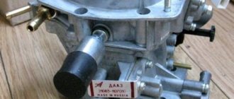
K151D
The Gazelle with the 406 engine had its own carburetor, and it was somewhat different from the Volgovsky, which came with the 402 engine. The markings on the carburetors were also different: the Volga had the K151S model, and the Gazelle had the K151D. Externally, the devices are exactly the same, the only difference is in the filling. In the K151D model, the nozzles of the accelerator pump inject fuel into both chambers of the carburetor at once; on the K151C, only into the first chamber. Carburetors also have different jet sections.
The carburetor ZMZ 406 on the Gazelle has one problem - the Gazelle’s rather high fuel consumption, especially when the car is loaded and travels at speeds above 60 km/h. The problem is still present, and every owner of a commercial vehicle is trying to solve it in his own way.
K-151 D
For Gazelle cars with a ZMZ-406 engine, the manufacturer has provided a separate carburetor. It differs from the element for the Volga with a 402 engine. Carburetors also had different markings. For the Volga the marking was K-151 C, and for the Gazelles it was K-151 D. Externally, both models of carburetors had no differences. There is a slight difference in the design, the rating of the jets and other technical nuances.
In the Gazelle carburetor, the accelerator pump nozzles supply fuel to two chambers, while for the Volga the accelerator pump operates only in the first chamber.
What are the disadvantages of this mechanism? The problem with this carburetor with the 406 engine is the huge fuel consumption. This is especially noticeable when the car is loaded (which is important for Gazelles) and moves at a speed of more than 60 kilometers per hour. This problem exists, and it is widespread. Owners of commercial vehicles are trying to solve it in any possible way.
Among the owners it is believed that this model is very capricious. The unit is not suitable for everyone; many often abandon this device in favor of other models.
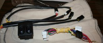
Solex 21073
At one time it was fashionable to install the DAAZ Solex 21073 carburetor on the Gazelle. The carburetor was sold in car shops even with an adapter included for a GAZ air filter; it was originally intended for installation on a Volga with a ZMZ 402 engine. But this fashion, however, passed quickly enough. Designed to save fuel, the Solex quickly became clogged.
Instead of saving money, it consumed even more fuel than the K151D, and the car did not want to drive normally. A typical problem in the “carba” model 21073 was the clogging of the idle jet on the solenoid valve, and when it was dirty, the engine generally refused to idle - it constantly stalled and did not develop power.
Carburetor malfunctions
What to do if the carburetor Gazelle begins to consume fuel significantly more than normal?
This is what a Solex 21073 carburetor looks like for a Gazelle
The following malfunctions occurred:
- Clogged jets. Moreover (you should pay attention), it was not the fuel jets of the main metering system that became clogged in the first place, as everyone usually assumed, but the idle channels under the adjusting screws. It’s interesting - the XX becomes clogged, but the engine does not work normally at medium speeds, and at the same time there is a high fuel consumption;
- The accelerator pump diaphragm breaks or the accelerator nozzle becomes clogged. The accelerator pump stops working. As a result, there is a dip when accelerating hard;
Accelerator pump diaphragm for Solex carburetor
There are still all sorts of problems with the carb, but the above-mentioned “sores” are more common. By the way, any malfunction of the carburetor invariably leads to an increase in fuel consumption, which is why this device causes a lot of headaches for Gazelle car owners.
Scheme for reducing consumption on the K-151 carburetor
Location and designation of carburetor jets K-151
First of all, you need to clog the hose that comes from the valve cover at the bottom of the carburetor; after these steps, the idle speed will become stable.
The procedure for reducing fuel consumption on the carburetor to 151:
- It is necessary to adjust the air and fuel jets.
- Adjust the ignition to the point of detonation.
- Correctly adjust idle speed.
Turn the large screw approximately the required number of revolutions.
Then use the large screw to lower the speed - not much more than the prescribed ± 100. And level it to the required amount with the small screw.
This is how to remove, install and configure the K 151 carburetor on a UAZ. As you can see, there is nothing complicated in this procedure and any novice driver can cope with it. We wish you good luck on the roads!
Adjustment
Fuel consumption directly depends on the adjustment, even if the carburetor is absolutely working.
There is only one external adjustment in the device - idle speed. How to do it correctly:
- We start the engine and warm it up to a hot state, then perform adjustments at idle speed;
- We unscrew the quantity screw (a large screw with a spring) and the quality screw until the engine reaches maximum speed;
- By evenly tightening both screws, we find the position when the engine starts to work with minimal interruptions;
- Using the quantity screw we set the speed to a slightly higher speed, at this point using the quality screw we achieve stable operation of the motor, but at the same time we need to try to keep the quality screw unscrewed to a minimum (as far as possible);
- Having adjusted the quality, turn the quantity screw until the optimal idle speed is obtained (700-750 rpm).
If there are malfunctions in the carburetor or engine that affect the stability of idle speed, there is no point in adjusting the idle speed - you must first fix the problem.
There are many reasons for unstable operation of the internal combustion engine - from a simply non-functioning spark plug or a piercing high-voltage wire, to a burnt-out exhaust valve or piston.
If you remove the carburetor housing cover, you can adjust the gasoline level in the float chamber. Adjustment is made by bending the tongue on the float.
Adjusting the Solex 21083 carburetor
The Solex carburetor has several types of adjustments, and you can adjust:
- gasoline level in the float chamber;
- number of minimum idle speeds;
- qualitative composition of the fuel mixture (FC) using the idle speed screw (IQ).
Adjusting the quality of the vehicle is very simple, and any car owner can do the adjustment with his own hands. To do this, you need to warm up the engine well and set the speed screw to 800-900 rpm. Then:
- tighten the quality screw until the internal combustion engine begins to operate with some interruptions and reduce the number of revolutions;
- We unscrew the screw so that the motor starts running smoothly again, usually one turn is enough. If the screw is loosened too much, fuel consumption will increase.
In other cases, you have to loosen the quantity screw more, since dips appear in the engine’s operation.
One of the most common idle problems is the inability to adjust the Solex 21083 carburetor using a quality screw - when it is tightened and unscrewed, the engine speed does not change. There are several reasons for this malfunction:
- the jet in the solenoid valve is clogged;
- the XX channel, which is located under the “quality” screw, is clogged;
- The solenoid valve (EC) itself is faulty.
It’s quite easy to check the functionality of the EC itself; we do it as follows:
- with the engine not running, remove the wire from the valve;
- unscrew the EC;
- we remove the fuel nozzle from it, it is pulled off by hand;
- turn on the ignition;
- We connect the wire to the EC - at the moment of contact, a dry, clear click should be heard, and the valve stem is recessed. If there is no click and the rod does not move, such an EC must be replaced.
It is also necessary to immediately blow out the nozzle - in some cases, such a small speck gets into it that it is practically invisible. There is also a problem with Solex - the idle channel under the quality screw becomes so clogged that it is impossible to clear it.
Fuel consumption – according to factory standards and real
According to technical passport data, fuel consumption at a speed of 60 km/h with the ZMZ 4063 and ZMZ 4061 engines is 10.5 liters, at a speed of 80 km/h – 13 liters. But during control measurements many factors are not taken into account:
- Car load;
- Weather;
- Road conditions;
- Technical condition of the car.
These standards can be met if the car is operated in the summer on a dry road, without a load and in fully working order. Much still depends on driving style. The harder the driver presses the gas, the more fuel is consumed. Gasoline consumption also depends on its quality. It has been noticed that fuel with a higher octane number is consumed less. Therefore, for the Gazelle it is preferable to fill with AI-95 fuel instead of AI-92.
Comparison table for fuel consumption in various modifications of the Gazelle car
The condition of the vehicle's fuel system directly affects fuel consumption and other technical characteristics of the engine. The carburetor is still used today as one of the most important elements and requires appropriate attention and care.
XX adjustment
The most important of all available adjustments is the idle speed setting. It is necessary to perform it on a warm engine. In this case, the ignition system and all other systems of the power unit must be fully operational.
You need to start and warm up the engine. Next, unscrew the screw with the spring - this is the mixture quantity screw. The quality screw is also unscrewed. The turnover should increase. Then both screws are tightened in turn until the engine begins to operate unstably.
What's next? Use the quantity screw to add speed, then use the quality screw to level out the operation of the motor again. But you should try to turn the latter as little as possible, although it is believed that it affects fuel consumption only at idle. Next, using the quantity screw, the engine speed is reduced to normal according to the tachometer. After setting up, it is better to check the machine in operation under loads. If necessary, adjust the idle speed again.
On topic: AMD Jaguar x86-64. Processor Specifications
Device
As with all carburetors, the tasks of this unit include preparing the fuel assembly (a mixture of air and fuel). Mixing must be carried out according to a clear and programmed scheme, otherwise the car engine will receive unbalanced power. The device must recognize the dissimilarity of power unit loads at idle, medium and optimal speeds.
Carburetor components:
- Housing with float chamber.
- Dampers controlled by an actuator integrated with the vehicle's gas pedal.
- A lid in which the design provides a locking mechanism and an air damper.
- The idle system is designed for stable operation of the engine in this mode. It, in turn, includes in the design a return channel, screws for settings with O-rings, jets, etc.
- The main dosing system (MDS) is necessary for direct mixing of fuel assemblies. Consists of channels for various purposes.
- The econostat is designed to enrich the fuel assembly when the engine is operating at its limit. In essence, this is a system of additional channels that supply additional portions of gasoline when the dampers are opened.
- An accelerator pump that allows the car to accelerate without any jerks or dips. A group of additional paths in a housing with a ball valve, a membrane and a fuel atomizer.
- The transition system is used to smoothly increase the speed. Refers to the secondary chamber, consists of separate jets.
Modifications of K-151
You should know that the K-151 model has several varieties. For example, on GAZ-31 or GAZ-32 cars the K-151 C version is used. The additional letter is of great importance for carburetor specialists involved in the selection of jets. The cross-section of the latter may be different, depending on the specific option.
- K-151 is a basic modification used on ZMZ 4021, GAZ-24, GAZ-31 vehicles.
- K-151 D is a model with additional sprayers on the accelerator pump and the ability to discharge the jet directly into the chambers. These modifications do not have a microswitch. One of the cars on which it is installed is GAZ-33.
Model K-151 D includes additional accelerator pump nozzles
Table: types of modifications of K-151 carburetors
| Model | Cars | GDS fuel nozzle dimensions | GDS air jet dimensions | Diffuser diameter, mm |
| K-151 | Volga GAZ-2410, -31029, 3102, 3110; Gazelle GAZ-33021, -33023, -33027, -2705, -27057 | 225/380 | 330/330 | 23/26 |
| K-151V, K-151G | UAZ-31512, -31514, -3741, -3962, -2206, -3303, -3909 | 225/330 | 330/230 | 23/26 |
| K-151D | Volga GAZ-3110 ZMZ-406; Sable GAZ-2752, -2217, -22171; Gazelle ZMZ-406 (except GAZ-33021) | 225/340 | 330/330 | 23/26 |
| K-151E | UAZ-3153, -33036, -39094, -39095 | 230/330 | 330/330 | 23/26 |
| K-151I | Volga GAZ-31029; Gazelle GAZ-3302 | 225/380 | 330/330 | 23/26 |
| K-151L | UAZ-31601 | 225/340 | 330/330 | 23/26 |
| K-151N | IZH-412IE, -21251, -2715-01, -27151-01 | 225/330 | 330/230 | 23/26 |
| K-151P | IZH-2126 Oda | 225/330 | 310/280 | 23/26 |
| K-151S | Volga GAZ-3102, -31029, -3110 ZMZ-402.10; Gazelle; Sable | 205/330 | 260/330 | 23/26 |
| K-151T | Gazelle UMZ-4215.10 | 235/330 | 280/330 | 23/26 |
| K-151U | UAZ-31512 ZMZ-402.10 | 225/380 | 330/330 | 23/26 |
| K-151TS | UAZ-33036, -31512 | 205/280 | 260/330 | 23/26 |
Sources used:
- https://vsekarby.ru/avtomobili/legkovye/karbyurator-k-151-regulirovka-remont.html
- https://swapmotor.ru/ustrojstvo-dvigatelya/karbyurator-k151.html
Basic faults
During the operation of carburetors of this series, problems can be identified by characteristic signs, manifested in the form of certain disturbances in the operation of the internal combustion engine.
Doesn't hold idle
The cause of a common malfunction that occurs when the fuel assembly is over-rich or lean is a violation of the adjustments of the exhaust system or clogging of the nozzles. It is also possible that the float in the chamber is installed crookedly.
If the carburetor is equipped with an electric valve, then you can do this. Loosen the regulator slightly and see if the speed returns to normal. If the nozzles are not clogged, this will happen. What is the reason? It turns out that everything is quite simple. Often the adjusting screw XX becomes loose during vehicle operation and falls out of the hole. This is the cause of the malfunction. To eliminate it, just screw it into place.
The adjusting screw K-151 may fall out due to the expansion of the hole
This bolt, if it is lost, can be purchased together with a repair kit for a suitable modification of the K-151. It is recommended to lubricate the hole with sealant, since most likely it has become loose and the screw does not hold it well. Some people advise using a piece of paper instead of glue; they need to wrap it around the tip of the regulator, and then screw it in. Naturally, this bolt is tightened thoroughly after the appropriate settings in idle mode.
Fills the carburetor
Overflow for all models of fuel mixing devices is a fairly common phenomenon. It occurs due to excessive enrichment of the fuel assemblies entering the engine. This is noticeable even to the naked eye; just pay attention to the leaks from the sprayers. At the same time, the smell of gasoline will reign not only in the engine compartment, but also partially penetrate into the interior of the cabin. At the same time, black smoke comes out of the muffler.
If the carburetor is heavily flooded, the engine unit may not start at all. Difficulties with the plant are especially often observed when the internal combustion engine is warm. Even after another successful attempt, a power unit with an overflow carburetor will not operate stably. Dips and jerks when pressing the gas pedal are clear confirmation of this.
The reason for this malfunction, as you might guess, is hidden in the float chamber. There are several possible scenarios here:
- The needle mechanism is damaged or stuck. If the latter, then it is enough to gently tap the device cover with a hammer so that the valve comes out of the open state. It is possible that the element is not tightly wrapped, or the sealing ring has dried out. Finally, the performance of the needle is tested by applying a vacuum to it (opening/closing).
- Doesn't hold the float. If there is a hole in it, then it will begin to sink in the liquid, pulling the needle valve with it. Gasoline will be constantly pumped into the chamber, since the access is not closed, and in the end, everything will end in an overflow of fuel. It is not difficult to identify a “broken” float. You need to take it off and shake it over your ear. If you hear the sound of liquid inside, it means that the element needs to be replaced or soldered for the first time.
- The float gets stuck and touches the walls of the chamber. This indicates a violation of its position in space. You just need to remove the top of the carburetor and, holding it vertically, check how it moves.
The carburetor float may be stuck
Among other things, the needle valve sometimes sticks, which is due to the presence of oil in gasoline . Impurities can settle inside the fuel tank, and then from there, forming in a sticky solution, penetrate the carburetor and damage the needle. The solution is usual: replacement in a repair kit, possibly along with jets and other elements. There is another option: treat the needle with diamond paste.
Carburetor freezing
If the air humidity is high, ice may form on the K-151 dosing elements in the autumn-winter period. This often happens when driving on highways at high speeds, since the damper is constantly open and the air is cold.
Obviously, freezing an element does not lead to anything good. Ice clogs the air channels of the transition system, the mixture instantly becomes over-enriched, and the spark plugs become overgrown with soot. Accordingly, fuel consumption increases, the engine operates intermittently, troits and may even stall.
As a rule, if this happens, then while driving on the highway the driver feels how the operation of the internal combustion engine changes. You need to stop the car, remove the filter cover and carefully inspect the surface of the diffusers. Then you should wait a few minutes, during which time the ice will melt and the power plant will continue to work.
Carburetor malfunctions can also be expressed in the following:
- The mesh that allows fuel to pass through becomes clogged. The solution is to wash the filter, and if it is severely deformed, replace it.
- The air damper does not close completely. The reason for this is incorrect drive adjustments. We need to set everything up again.
- The idle air control valve does not work. This happens for two reasons: an open circuit or a malfunction. In the first case, it is necessary to eliminate the break, in the second, to replace the part.
- It sucks air through the carburetor body. It is good to tighten the clamps and update the old gaskets.
Main malfunctions of the K151 carburetor
During the operation of these dosing devices, malfunctions are possible, which are detected by signs of engine malfunction.
Doesn't hold idle
This malfunction often occurs due to a lean fuel mixture. The reason for this is a failure in the neutral settings of the carburetor or simple clogging of the channels. Another possibility is that the float in the chamber is installed crookedly.
Carburetors equipped with an electric valve are regulated as follows:
- loosen the XX adjustment screw slightly;
- check the speed;
- if they have changed, tighten the screw until the speed returns to normal.
In some cases, this bolt even falls out of place. You can buy it in a repair kit or separately. Before installation, it is recommended to lubricate the hole with sealant or simply wrap the tip of the screw with paper.
Fills (overflows)
Overfilling, which occurs due to over-enrichment of the gasoline mixture, is also not uncommon. It is easy to determine this malfunction; just pay attention to the strong smell of fuel and fuel leaks from the nozzles. Black smoke may also come out of the exhaust pipe.
As a rule, overflow prevents the engine from starting normally. This is especially true on warmed-up engines, which even after a successful restart attempt are unstable. When the accelerator is activated, dips and jerks begin.
To correct the situation, just adjust the float chamber. There are several options on how to proceed:
- Damage to the needle valve. It is necessary to check the functionality of the needle - a vacuum is applied to it and the opening/locking is tested. Read more about valve repair below;
- Valve stuck. In this case, you need to tap the carburetor cover lightly with a hammer. This will affect the valve. It is possible that the seal has dried out or the element is not wrapped tightly enough;
- Valve sticking. This happens due to oil getting into the fuel. Impurities can settle in the fuel tank and from there penetrate into the metering device in the form of a sticky solution. The problem can be solved by replacing the entire repair kit, possibly together with the jets. A less expensive option is to treat the needle with a special paste;
- Float destruction. The damaged element will simply begin to sink in gasoline, dragging the valve with it. For this reason, liquid will be constantly pumped into the chamber, which will cause overflow. A leaky float can be identified by the sound of the liquid in it - just remove it and shake it over your ear. As a last resort, the part is allowed to be soldered;
- The float is stuck, touching the walls of the housing. This already indicates an incorrect position setting. It is also recommended to check the float stroke with the top of the carburetor placed vertically - naturally, the top must be removed before the test.
System freezing
In autumn, and especially in winter, K-151 can freeze. This happens when driving on roads at high speed. The reason is that the air damper remains constantly open. This situation poses a big problem. The ice will close the air holes in the dispenser. The mixture will begin to become over-rich, and the spark plugs will become overgrown with soot.
What to do? While driving on the highway, determine by ear that the nature of the internal combustion engine has changed, and stop. Remove the top of the air filter and carefully inspect the diffusers. If there are solid drops in this place, wait a little - the ice will melt and you can continue on your way.
Other causes of carburetor freezing:
- solenoid valve XX is damaged;
- the filter mesh is clogged or damaged;
- the air damper does not close completely;
- sucks air through the device connections.
Modernization and repair of K-151 carburetors
In principle, it is considered a good carburetor. However, today there is no such mechanism in the automotive sector that would not need modifications and improvements.
The float chamber fuel shut-off valve is being modernized. In most cases, fuel leaks out of it, causing the gasket to get wet. Sometimes gasoline may leak onto the surface of the housing.
It’s easy to improve this point:
- The carburetor is disassembled.
- The gasket is removed.
- This adjusting screw is turned out.
- The float is removed.
- The valve is removed.
Fuel shut-off valve needs improvement
How to disassemble K-151
It should be borne in mind that there are quite a few varieties of the K-151 carburetor. However, the principles of disassembly and assembly are almost the same for everyone. Before starting dismantling, you need to mentally imagine the carburetor consisting of three main parts: the cover, the throttle body (middle part) and the bottom. These are the ones you need to work with:
- The top cover of K-151 is removed. It can be easily dismantled; just remove a few bolts.
The top cover of K-151 is easily dismantled
The diffuser on the K-151 is also removable
The screw on the side holds the axle with the float
The jet disassembly diagram will help you remove and reassemble everything correctly
The accelerator pump bolts are unscrewed with a flat-head screwdriver.
The throttle body is removed by unscrewing two screws
The throttle body is separated from the bottom of the K-151. There are two gaskets under the housing; they are also removable. The main components of the carburetor can be thoroughly disassembled, although this is not so necessary if you just need to clean the jets, holes and channels. Disassembling the carburetor is mandatory; if the jets are clogged, it is necessary to blow out or wash the internal parts of the K-151.
Do-it-yourself carburetor adjustment K-151
When experienced motorists casually throw out the phrase “before, technology was extremely reliable,” they are, in a certain sense, right. Indeed, is it worth comparing the level of complexity of a modern car and its analogue from 50-60 years ago? And if the product is simple, then by definition it is more reliable. Owners of cars of the latest generations will certainly agree with this: if major breakdowns at the initial stage of operation are very rare, then you only need to have time to deal with minor faults.
Carburetor K-151E
In this aspect, the products of the Leningrad Carburetor Plant can be considered legendary, and its flagship is rightfully recognized as the K-151 carburetor, better known under the pseudonym Pekar. Its reliability is legendary; it is no coincidence that it is used on vehicles with ZMZ and UZAM power units, in particular on the famous domestic UAZ SUV. But, as you know, this device demonstrates the greatest efficiency with the correct settings. Today we will tell you how to achieve this.
Assembly of the unit
Assembly is carried out in the same way, only the actions are carried out strictly according to the reverse dismantling scheme. It is necessary to replace the gaskets if their condition raises questions. Clean everything thoroughly using a special carburetor fluid or a rag soaked in gasoline.
It is recommended to start assembly with the jets, which just need to be put in place. It is important to decide on the primary and secondary cameras so as not to confuse the channels. Some tubes are short, others are long, this must be taken into account.
Here are some important assembly tips:
- The primary chamber can be immediately identified by the direction of the fuel spout towards it.
The fuel spout is always directed towards the primary chamber
An emulsion nozzle with 5 rows of holes is placed in the first chamber
The membrane must have an iron tip
The pump spring must be placed under the cover
Now important recommendations for installing hoses:
Fittings K-151 for connecting hoses
- A hose from the idle speed solenoid valve is attached to the lower carburetor fitting, number 6.
- A hose is placed from the valve onto the idle speed economizer into fitting 3. Otherwise it is called a vacuum intake tube.
- A hose from a distributor or vacuum regulator is mounted in output 7.
- K 5 - small crankcase ventilation hose.
The K-151 carburetor is considered a reliable device. However, it needs adjustment, disassembly and cleaning from time to time.
The K-151 carburetor is designed to equip ZMZ four-cylinder power units with a volume of 2.45 liters, which were once equipped with cars of the GAZ and UAZ families. The production of three modifications of the engine power supply device has been launched: K-151, K-151V and K-151N. The K-151N modification is more focused on UAZM engines.
Like all components and assemblies in the car system, the carburetor must be regularly maintained and repaired at the first symptoms of a malfunction. In this article we will look at the features of the design, adjustment, repair and connection of the K-151 carburetor.
Adjusting the PU carburetor K-151
The starting device is a unit that is the source of the signal informing about the start of the power unit. If the elements of the starting system are faulty or do not work correctly, you will not be able to start the car. But even with a working starting mechanism, problems are possible that make starting difficult. To correct them, the K-151 carburetor is adjusted, and such work can be carried out both on a dismantled and on a working device installed on the engine.
Adjustment on a dismantled Pekar is carried out in the following order:
- open the remote control slightly and look for the control lever;
- turn it to its extreme position and fix it with something suitable (rope, wire);
- release the remote control to its original position. In this case, the gap between the chamber wall and the edge of the damper should be within 1.5±0.3 mm;
- unscrew the locknut that blocks the rotation of the stop screw located on the remote control lever;
- We turn the screw itself in stages, half a turn each time. At the same time, we must ensure that when tightening the locknut, the screw is located perpendicular to the cam, otherwise the control unit will not work;
- We check the thrust valley, with the help of which the PU cam is connected to the air damper levers. With the PU lever turned to its extreme position and the air intake completely closed, it is necessary to achieve a gap between the levers within 0.2-0.8 millimeters. If this is not the case, adjustment is made by releasing or tightening the rod head, which allows the rod itself to be shortened or lengthened.
Adjustment of dampers K-151
You can adjust the PU of the K-151 carburetor without removing it, and this will not affect the quality of the setting.
- dismantle the car air filter (of course, without removing the box);
- start the engine at XX;
- by pressing the accelerator pedal, open the air damper and pull out the shifter - the mechanism responsible for controlling the operation of the air damper;
- Using a screwdriver with a flat tip, open the air intake slightly; in this case, it is necessary to determine the rotational speed of the power unit shaft (reference point: 2600±100 revolutions/minute). If the speed is much higher, we perform a similar operation to the one that was performed on the removed carburetor: unscrew the lock nut that locks the rotation of the adjusting screw of the lever that drives the throttle body;
- after unscrewing the locknut, screw in the crankshaft; if it rotates slower than necessary, screw in the crankshaft;
- tighten the locknut.
After adjusting the trigger mechanism, it is necessary to run in the carburetor.
Important! Before carrying out adjustment work, you should determine and record fuel consumption when operating in different modes in order to be able to compare with the indicators achieved after adjustment.
Device design
To ensure that the engine can operate at any speed, the carburetor prepares the fuel-air mixture. Despite the fact that the individual systems of the K-151 carburetor are made according to standard designs, all three modifications differ from other devices in their layout. The advantage of the K-151 is the shut-off needle located in the body, which greatly simplifies the adjustment of the gasoline level. In general, the entire assembly can be divided into three parts with a base in the form of a float chamber.
Other important design elements are:
- Locking mechanism located in the top cover of the float chamber;
- Dosing system consisting of air and fuel jets;
- Adjusting screws and economizer valve of the XX system;
- Eliminates dips during vehicle acceleration using a special accelerator pump with a fuel sprayer;
- At high speeds, the fuel assembly enriches the econostat;
- A transition system is necessary to gradually increase the number of revolutions at the moment the secondary chamber opens.
The K-151 received two chambers, which guarantees continuous movement of fuel in the event of any breakdown. The fuel level is adjusted automatically due to the ability to close the valve opening with a shut-off needle. The operating principle is as follows: if there is not enough gasoline in the chamber, the float lowers and releases the needle. As the chamber fills, the float rises, followed by the needle closing the valve cross-section. The lower compartment houses the primary and secondary throttle valves with control actuators. During operation, they open alternately, fuel passes through a mesh filter mounted in the fitting, due to which gasoline enters the system without impurities and inclusions.
Device K-151
Let's consider the design of this mechanism. The design of the Gazelle 406 carburetor is relatively simple. The unit consists of several elements. It must be said that the carburetor has two chambers.
This device consists of several parts. This is the main body or middle part in which the float chamber is located. Next there is a housing where the throttle valves are installed. Also in the design of the unit, you can highlight the top cover; it has a locking mechanism that allows you to regulate the amount of fuel in the float chamber. There is also an air damper in the lid, which can be used to start a cold engine.
Next, we can highlight the important systems of the Gazelle carburetor. This is the main metering system and the idle system. The GDS or main metering system is very important; it is the main one in the process of preparing the fuel mixture for the main operating modes of the engine. The GDS consists of two fuel jets and two air jets for the first and second chambers.
On the subject: Turkey broth: recipe with photos
The idle system is necessary to ensure that the engine operates in idle mode when the main metering system is not engaged and not operating. This system consists of a bypass channel, jets - fuel and air, screws for adjustment - screw for the quantity and quality of the fuel mixture. The device also includes a solenoid valve.
The K-151 D carburetor is equipped with an accelerator pump. It is necessary so that the engine can operate without any failures when sudden acceleration is necessary or when starting to move. The accelerator pump consists of additional channels in the housing, a ball valve and nozzles.
This carburetor also has an econostat. This system is needed to enrich the mixture when the engine is running at maximum loads. An econostat is an additional special channel through which, due to vacuum and open throttle valves, a portion of gasoline is supplied, which is designed to enrich the mixture.
There is also a transition system. When the GDS has not yet started working, and the throttle valve is slightly open, the engine is powered using the transition system, and it can smoothly increase the speed. There are two transition systems: for the first and second chambers.
Service
Carburetors are reliable and unpretentious devices. K-151, like other components in the automotive system, requires periodic maintenance. Basically, problems arise in the event of unqualified intervention in its design or due to inappropriate maintenance. Neglecting the simplest maintenance procedures for the K-151, it may happen that the carburetor ceases to function fully due to the clogging of the calibrated holes with hard tarry deposits. For its correct operation, it is necessary to timely adjust the main systems.
Carburetor repair K-151
Over time, various breakdowns can occur with the carburetor, because all its elements have their own resource. Most often, a faulty K-151 unit provokes increased fuel consumption and reduces the dynamic performance of the vehicle. There are often cases when black smoke pours out of the exhaust pipe, and the car refuses to pick up speed at all. All these problems with the car in most cases are caused by a malfunction of the fuel system. The operation of the K-151 is greatly affected by various deposits that interfere with the normal operation of the jets. You can check their condition and clean the jets quite simply, but to do this you need to disassemble the carburetor itself.
Let's disassemble the mechanism
It is advisable to completely disassemble the assembly in cases where there are no other possibilities to get to any structural element. To check the condition of the jets and clean them, simply remove the top cover of the housing. You can carry out all the work quickly and efficiently with the help of an arsenal of the necessary tools.
The procedure for completely disassembling the K-151 carburetor is as follows:
- Remove it from the cotter pins by unscrewing the four nuts.
- Clean the housing from dirt and dust.
- Loosen the seven cover screws.
- Remove the special cotter pin and rod.
- Loosen the two float chamber screws.
- Remove the econostat sprayer.
- Turn the seats of the needle valve with the horn to “12”, and unscrew the screw of the filter fittings to “22”.
- The fuel filter is removed along with the gaskets, after which the float chamber itself is dismantled.
Further disassembly of the K-151 involves dismantling the air and fuel jets, the idle speed unit, the accelerator pump and removing the quality screws. The carburetor must be completely disassembled at the time of its comprehensive flushing. Most auto mechanics prefer to completely replace the jets with new ones. For these purposes, you can use the jet table. But it is worth saying that they fail only in exceptional cases. Often, washing and blowing them is enough to restore their previous functional properties.
Assembling and connecting hoses
When assembling the unit, you must be extremely careful. It is important to remember the order in which the mechanism is disassembled and during assembly proceed in the reverse order. All elements should be installed in their places and securely fastened. Initially, quality screws and two screws are screwed into the empty housing to secure the throttle valves.
Old or new jets are screwed into the sockets, the fuel block and idle are connected. After which the float chamber is installed and secured. It is important not to forget to replace the float and needle itself. Many domestic drivers are also faced with the need to connect the K-151 carburetor hoses to the ZMZ-402.
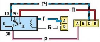
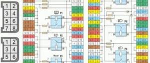
The photo shows a diagram of the K-151 carburetor.
All hoses and tubes are connected in the following way:
- The largest fuel supply pipe is connected to the float chamber.
- A fuel return hose is connected to the lower outlet of the carburetor.
- Smaller diameter hoses are connected to the economizer and to the throttle valves.
- Then the vacuum hose is connected.
- The forced ventilation hose is connected to the top terminal of the carburetor.
Connecting the hoses is a fairly simple and easy job. But a beginner can easily get confused about their purpose, so at the first stage it is recommended to leave the corresponding markings on their surface with a marker while disassembling the carburetor. By taking simple steps to clean the carburetor parts, you can significantly extend not only the service life of the K-151, but also the main power unit of the car.
Design of the K-151 carburetor of the ZMZ-402 engine
K-151 carburetors are installed on GAZ-3110, GAZ-3102 Volga, Gazelle 2705 cars with ZMZ-402 engines.
The K-151D carburetor is installed on ZMZ-406 engines, but its difference from the K-151 carburetor is insignificant. Structurally, they are made identically, but the difference lies in the sizes of some calibrated holes.
The K-151 / K-151D carburetor (Fig. 1) consists of three main detachable parts connected through sealing gaskets with screws. The upper part - the carburetor cover - includes an air pipe divided into two channels, with an air damper in the primary section channel.
The middle part of the carburetor consists of a float and two mixing chambers and is the carburetor body.
The lower part - the throttle body - includes mixing pipes with throttle valves of the primary and secondary sections of the carburetor. The gasket between the middle and lower parts of the carburetor is sealing and heat-insulating.
Fig.1. Carburetor diagram K151 / K151D for GAZ-3110 Volga, GAZ-3302, 2705 Gazelle cars
A - control circuit for the forced idle economizer; 1 - fuel valve; 2 - float; 3 - plug; 4 — air jet of the transition system; 5 — emulsion jet of the transition system; 6 — screw securing the secondary section nozzle; 7 — secondary section sprayer; 8 — air jet of the main dosing system of the secondary section; 9 — emulsion tube of the main dosing system of the secondary section; 10 — small diffuser of the secondary section; 11 — exhaust ball valve of the accelerator pump; 12 — accelerator pump nozzle; 13 — air damper; 14 — small diffuser of the primary section; 15 — air jet of the main dosing system of the primary section; 16- emulsion tube of the main dosing system of the primary section; 17 — air jet unit with emulsion tube of the idle system; 18 — emulsion jet of the idle system; 19 — air jet of the idle system; 20 — screw for factory adjustment of mixture composition; 21 — main fuel jet of the primary section; 22 - plug; 23 — carburetor cover; 24 — adjusting screw for fuel bypass of the accelerator pump system; 25 — displacer; 26 — carburetor body; 27 — inlet ball valve of the accelerator pump; 28 — accelerator pump cover; 29- spring; 30 — accelerator pump drive lever; 31 - accelerator pump diaphragm; 32 - solenoid valve; 33 — electronic control unit; 34 - microswitch; 35 — accelerator pump bypass jet; 36 - tube; 37 - forced idle economizer diaphragm; 38 — forced idle economizer valve; 39 — restrictive cap; 40 — mixture composition screw; 41 — forced idle economizer housing; 42 — idle speed adjustment screw; 43 — tube to the vacuum corrector; 44 — throttle valve of the primary section; 45 — accelerator pump lever drive cam; 46 — accelerator pump lever roller; 47- throttle body; 48 — throttle valve of the secondary section; 49- tube for supplying vacuum to the solenoid valve; 50 - calibrated hole; 51 - gasket; 52 — main fuel jet of the secondary section; 53 — tube to the exhaust gas recirculation valve; 54 — crankcase gas supply tube; 55 — fuel supply pipe; 56 — drain tube; 57 - fuel filter
Structurally, the K-151 / K-151D carburetor consists of two functional sections (mixing chambers) - primary and secondary. Each section of the ZMZ-402 (GAZ-402) carburetor has its own main metering system.
Idle system - with quantitative regulation of constant mixture composition (autonomous idle system). In the secondary section of the K151 / K151D carburetor there is a transition system with fuel supplied directly from the float chamber, which comes into operation when the throttle valve of the secondary section opens.
Diaphragm type accelerator pump. To enrich the combustible mixture at full load, an econostat is provided in the secondary section.
Fig.2. Scheme of a semi-automatic device for starting and warming up K-151 / K-151D for GAZ-3110 Volga, GAZ-3302, 2705 Gazelle cars
1.5, 6, 16 - levers; 2 — starting spring; 3 — intermediate lever; 4 — pneumatic corrector rod; 7 - traction; 8 — sector lever; 9 — air damper; 10 — carburetor cover; 11 - sealing element; 12-adjusting clutch; 13- float chamber body; 14 — air damper drive lever; 15 — thrust screw of the throttle valve of the primary section of the carburetor; 17 — throttle valve of the primary section of the carburetor; 18 — housing of mixing chambers; 19- screw with roller; 20 — emphasis; 21 - pin; 22 — profile lever; 23 — pneumatic corrector spring; 21 — pneumatic corrector cover; 25 - aperture; 26 — pneumatic corrector jet
The cold engine starting system ZMZ-406 / 402 of GAZ-3110 Volga, GAZ-3302, 2705 Gazelle cars (Fig. 2) is a semi-automatic type, consists of a pneumatic corrector, a system of levers and an air damper, which is closed before starting a cold engine by the driver using manual drive.
When the engine starts, the pneumatic corrector, using the vacuum that occurs under the carburetor, automatically opens the air damper to the required angle, ensuring stable operation of the engine when warming up.
When pulling out the choke lever, you must press the throttle pedal.
The fuel supply cut-off system for internal combustion engines ZMZ-402 / 406 of GAZ-3110 Volga, GAZ-3302, 2705 Gazelle cars (forced idle economizer) comes into operation in forced idle mode when the car is braking by the engine, when there is no need to supply fuel to the engine.
This ensures fuel savings and reduces the emission of toxic substances into the atmosphere.
The fuel supply shut-off system for the ZMZ-406/402 internal combustion engine consists of a control unit 33 (see Fig. 1), a microswitch 34, and a solenoid valve 32 for the forced idle economizer.
The forced idle economiser microswitch is located on the carburetor, the solenoid valve - control unit - on the front panel of the cab.
The control unit is a device that, depending on the frequency of electrical pulses coming from the ignition coil, controls the solenoid valve 32. When the throttle pedal is released, the contacts of the microswitch 34 must be open.
The fuel supply shut-off system for the internal combustion engine ZMZ-402 (GAZ-402) of the GAZ-3110 Volga, GAZ-2705 Gazelle cars works as follows:
When the throttle pedal is released and the engine crankshaft speed is more than 1400 rpm, the control unit does not supply voltage to the solenoid valve, as a result of which atmospheric air enters the forced idle economizer through the channels of the solenoid valve, the valve of which closes the idle channel.
All carburetor systems are connected to a float chamber, the fuel level in which is maintained by float 2 and fuel valve 1 (see Fig. 1).
The fuel lines between the fuel pump, fine filter and K151 carburetor are made of rubber hoses and brass tubes with an outer diameter of 8 mm.
It is recommended to disassemble the K-151 / K-151D carburetor in the following sequence:
— unscrew the screw securing the air damper rod to the drive lever;
— unscrew the seven screws securing the float chamber cover, remove the cover and the gasket under it, being careful not to damage the gasket;
— unscrew the two screws and remove the air damper if the gaps between the air damper and the air pipe exceed normal values;
- Unscrew the screw and remove the accelerator pump nozzle;
— unscrew the screw and remove the econostat sprayer;
— unscrew the plug and remove the float axis, remove the float, remove the fuel valve needle. Unscrew the fuel valve body together with the gasket;
— unscrew the filter plug and remove the mesh filter;
— unscrew the four screws securing the accelerator pump diaphragm cover, remove the cover and remove the diaphragm with the spring;
— unscrew the main jets of the primary and secondary sections of the ZMZ-406/402 carburetor;
— unscrew the air jets and remove the emulsion tubes of the primary and secondary sections;
— unscrew the idle system jets of the primary section and the transition system jets;
This is interesting: Cord to laptop for car diagnostics
— unscrew the two screws and remove the diaphragm locking device of the forced idle economizer;
— unscrew the three screws and remove the housing of the autonomous system.
After disassembly, you should thoroughly rinse the outer and inner surfaces of the cover, carburetor body K151/K151D, diffusers, throttle body, clean off tar deposits and rinse fuel, air and emulsion jets, as well as channels in the body.
Unleaded gasoline should be used for flushing. After washing, the carburetor and its parts should be blown out with compressed air.
Washing the carburetor ZMZ-406 / 402 of GAZ-3110 Volga, GAZ-3302, 2705 Gazelle cars with solvents and wiping parts with wiping ends is not allowed. Cleaning calibrated holes with metal objects is strictly prohibited.
The technical condition of the K-151 / K-151D carburetor parts must meet the following requirements:
— all parts must be clean, free of soot and resinous deposits;
— after washing and blowing with compressed air, the jets must have a given throughput or size;
— all valves must be sealed, the gaskets are intact and have traces (prints) of the sealing planes;
— there should be no noticeable wear (play) in the connections: float axis - float bracket, mixing chamber housing bosses - throttle valve axis.
The carburetor is assembled in the reverse order of disassembly. First you need to assemble all three carburetor bodies: the cover, the float body and the mixing chamber housing, and then connect them together.
When assembling the K-151 / K-151D carburetor for GAZ-3110 Volga, GAZ-3302, 2705 Gazelle cars, you must:
— monitor the safety and correct installation of gaskets;
— make sure that the throttle and air dampers turn completely freely, without jamming and tightly cover their channels;
- tighten all threaded connections tightly, but without excessive force, avoiding warping of the flanges;
— check and, if necessary, adjust the fuel level in the float chamber.
Adjusting the starting system of the K151 / K151D carburetor
Adjusting the starting system on a carburetor removed from the car:
Opening the throttle slightly, turn and secure the starter control lever in any way (with wire, rubber band) until it stops.
Release the throttle valve and use a round gauge (for example, a drill) to check the gap between its edge and the wall of the mixing chamber, which should be 1.5. 1.8 mm.
Adjustment of the K-151 / K-151D carburetor of the ZMZ-402/406 engines of the GAZ-3110 Volga, GAZ-3302, 2705 Gazelle cars should be done by unscrewing the lock nut and rotating the stop screw with a flat head on the throttle lever.
When choosing the position of the stop screw, it should be taken into account that for its correct interaction with the cam, the plane of the screw head must be perpendicular to the plane of the cam when the locknut is finally tightened.
In other words, you can change the position of the screw each time by at least half a turn, otherwise its head will touch the cam with only one point, and not a line, as provided for by the design of the mechanism.
Next, proceed to check and adjust the active length of the rod connecting the cam lever of the starter control with the levers on the air damper axis.
With the starter control lever turned all the way and the air damper completely closed, the gap between the levers on the air damper axis should be within 0.2. 0.8 mm.
If there is no specified clearance on carburetors of the first releases, increase the length of the rod by unscrewing its threaded head, and on carburetors of later releases, by unscrewing the screw securing the lining on the cam of the starting device and moving it up, then tightening the screw.
If the gap between the indicated levers is excessively large, reduce the active rod length accordingly.
Finally, adjust the gap at the lower edge of the air damper after starting, i.e. when there is a vacuum in the cavity of the diaphragm mechanism of the trigger and its rod is fully retracted.
To this end, without releasing the trigger control lever, press the blade of a screwdriver from above onto the L-shaped rod of the trigger device diaphragm, simulating the action of vacuum.
In this case, the above gap between the edge of the air damper and the wall of the carburetor air neck should be 6 ± 1 mm.
Adjusting the starting system of the K151 / K151D carburetor on a car
Adjusting the starting system of the K-151 / K-151D carburetor of the ZMZ-402/406 engines directly on the GAZ-3110 Volga, GAZ-3302, 2705 Gazelle car allows you to achieve the desired results with guaranteed confidence in the correctness of its implementation.
To do this, start the engine with the air filter removed and, while slightly opening the throttle valve by lightly pressing the accelerator pedal, fully pull the air valve control lever towards you.
By forcibly opening the air damper as far as the lever mechanism allows with the blade of a screwdriver, make sure that on a warm engine the crankshaft speed is 2500. 2700 rpm.
If the crankshaft rotation speed differs significantly from these values, then you should unscrew the locknut on the adjusting screw-stop of the primary chamber throttle lever and turn it out several half-turns to increase the rotation speed, or vice versa, tighten it to decrease the rotation speed. After completing the adjustment, the locknut on the stop screw should be tightened.