Device
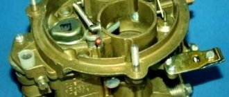
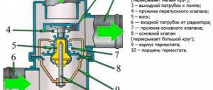
The DAAZ carburetor consists of a number of elements that provide certain qualities of the fuel composition.
DAAZ carburetor.
Since the engine operates in different modes, each of them requires a certain consistency of the combustible mixture. Since the carburetor includes more than 50 elements, each of which is important for the operation of the system as a whole, it would not be superfluous to consider them in more detail.
A diffuser is used to supply fuel from the carburetor. The diffuser is the narrowed part of the carburetor neck. When passing through it, a pressure drop occurs, due to which gasoline is forced out of the float chamber into the neck of the carburetor. In the neck itself, gasoline is mixed with air and, using the intake manifold, is supplied to the engine cylinders.
The main DS (dosing system) of the carburetor is designed to ensure the supply of the fuel mixture at medium speeds. The system itself consists of such elements as:
- emulsion jet and econostat channel
- air jet main DS
- air and fuel jets of econostat
- needle valve
- float
- float chamber
- emulsion well
- main fuel jet
- throttle shaft
- spool
- small and large diffusers
- spray.
The DAAZ carburetor includes two main DS. They are an enrichment device that is connected to a pneumatic drive, a suction system and is designed to pump out crankcase gases.
The main fuel jet is located in the channel, which is located between the float chamber and the nozzle. The atomizer is a tube with holes for air.
DAAZ carburetor design.
It is in the atomizer that the atomized combustible mass is created. The nozzle is necessary to determine the required volume of fuel for mixing. The fuel jet is a calibrator, which in the process changes the dimensions of the fuel supply channel.
Throttle valve (DZ)
Using the damper, it becomes possible to start a cold engine by enriching the combustible mixture. The air supply to the carburetor is stopped, due to which the gasoline level increases. During the procedure, the idle speed is reduced.
The DS drive consists of a pneumatic drive nozzle, DS drive levers, a DS axis, a pneumatic drive rod, a vacuum supply channel for the pneumatic drive and a rod bushing. The second remote control has a pneumatic drive and a special starting device for starting a cold engine.
Starting device (PU)
The starting device powers the entire system. It includes:
- air damper and pipe of the first chamber
- diaphragm and trigger rod
- choke control lever and adjusting screw
- throttle lever
- damper axes.
Acceleration pump
Provides additional fuel during a sharp opening of the remote control. It is designed to prevent engine stalling and interruptions during vehicle acceleration.
The accelerator pump consists of the following: bypass jet, accelerator pump drive, return springs, diaphragm cup, pump vapor chamber, inlet ball valve, nozzle, screw valve, float chamber, fuel channel.
Idle system (idle speed)
The system is designed for a steady supply of fuel while the engine is running at low speeds, while the main throttle body is not working. The idle system includes the following elements:
- air supply channel
- air damper
- air jet
- economizer cover and housing
- connecting hose between economizer and pneumatic valve
- emulsion well
- Remote sensing of the first camera
- adjusting screws for the quality/quantity of the combustible mixture.
Carburetor starter 2105, 2107 Ozone
The situation when a cold car engine refuses to start is known to almost any motorist. There are many reasons for this problem. Approximately 25% of their total number is due to a malfunction of the carburetor starting device. Often, owners of carburetor cars do not pay due attention to this small but very useful device. But in vain. With a fully functional and correctly adjusted carburetor starting device, starting the engine turns into a simple and easy procedure (you don’t need to constantly press the gas pedal, trick with pulling out and retracting the “choke” handle, etc.).
To better understand what it is - a carburetor starting device, and in connection with this, in the future, to properly regulate and configure it, you should know its purpose, structure and principle of operation. So, the object of our consideration will be the starting device of carburetors of the 2105, 2107 Ozone family. It should be noted that the starting device is present on all 2105, 2107 Ozone carburetors.
Purpose of the carburetor starting device 2105, 2107 Ozone
The carburetor starting device 2105, 2107 Ozone is designed to ensure a reliable start of a cold car engine. This is achieved by strong forced enrichment of the fuel mixture (2-3 times richer than when starting a warm engine) entering the engine cylinders during start-up mode.
Design and purpose of the main parts of the carburetor starting device 2105, 2107 Ozone
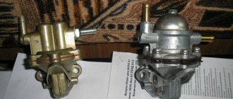
The images below show visible elements of the carburetor starting device 2105, 2107 Ozone.
On the front of the carburetor.
Elements of the carburetor starting device 23105, 2107 Ozone (front view)
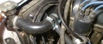
On the side part, the channel for supplying vacuum when starting the engine is clearly visible, from the throttle space into the cavity behind the diaphragm of the semi-automatic air damper opener of the carburetor 2105, 2107 Ozone.
Elements of the carburetor starting device 2105, 2107 Ozone (side view)
And this is a hole in the channel for supplying vacuum from the throttle space. It is only visible if you remove the carburetor.
Elements of the carburetor starting device 2105, 2107 Ozone (bottom view)
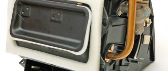
If you disassemble the carburetor a little - remove the cover and disassemble the opener body, you can again see the vacuum supply channel, the diaphragm in the opener body and the adjusting screw under the plug.
Parts and elements of the housing of the diaphragm trigger mechanism of the carburetor 2105, 2107 Ozone
You can imagine the starting device of the carburetor 2105, 2107 Ozone in the form of a diagram, as is done in many manuals and books on carburetors.
Diagram of the starting device for carburetors 2105, 2107 Ozone
Notes and additions
— The triggering threshold of the semi-automatic starting device is about 1500 rpm. Therefore, to reliably start the engine, it is also important to have a working starter and a charged battery.
— Remove the air filter housing and start the engine. Take a look at the carburetor from above. The air damper on it should automatically open slightly to the required starting gap. If it does not open slightly, the diaphragm in the opener body may be damaged, or the connections of the vacuum supply channel of the starting device may not be sealed.
TWOKARBURATORS VK -More information on the topic in our VKontakte group
More articles on Ozone carburetors
— Design of the upper part (cover) of carburetors 2105, 2107 Ozone
— Disassembling carburetor 2105, 2107 Ozone
— Diagram of carburetors 2105, 2107 Ozone
— The car engine starts and stalls (reasons related to the carburetor)
— Adjusting the carburetor air damper drive 2105, 2107 Ozone
— Pneumatic drive of the throttle valve of the second Ozone chamber, device diagram
Principle of operation
It doesn’t matter what model of carburetor, the process of its operation is the same everywhere. Let's look at it in more detail.
DAAZ carburetor parts.
As the engine operates, the pressure in the intake manifold decreases, which in turn creates a vacuum in the carburetor. After this, air is drawn into the carburetor and gasoline is captured. These ingredients are mixed together to form a flammable mixture. The mixture entering the combustion chamber ignites and drives the pistons. The volume of finished fuel depends entirely on the pressure in the mixing chamber.
The supply of gasoline and air is regulated by the gas pedal, which is connected to the air damper and the part that covers the float chamber. If the pedal is not subject to pressure, the engine is idling. The air intake almost closes the air supply channel, while the needle closes the opening in the fuel chamber.
The needle itself is constructed of several parts with individual thickness, and the higher it rises, the higher the level of fuel supply. The air damper works in a similar way.
Carburetor adjustment
The adjustment is carried out exclusively on a warm engine.
Float chamber. Control of the liquid level in the vessel is carried out using a float, which is connected to a needle. The level of the required amount of fuel is indicated in the machine’s operating manual. We measure current standard data using a caliper. If the data is higher than normal, the float bends downward by acting on the wire. If the data is lower, the float is raised in the same way.
Setting XX. The most optimal number of idle speeds is considered to be 800-900. To configure, perform the following steps:
- tightening the quality screw until it stops, after which it is unscrewed 4-5 turns
- tightening the quantity screw until it stops, after which it is unscrewed 3 turns
- turning on the motor and gradually tightening the first screw
- When the engine begins to operate unstable, the adjusting screw is tightened until stable operation begins
- adjustment with quantity screw.
Adjusting the jets. We close the air intake using a choke. In this case, the rod shank should be located at the end of the groove of the PU carburetor rod. If a deviation is observed, the rod is bent.
The cover is removed and the gap from the edge of the chamber wall to the air intake is measured. Standard indicators are in the instruction manual. The adjustment is made using the adjusting screw of the starting device.
The design of the Ozone carburetor. Carburetor starter
A carburetor is a device for precise dosing of fuel in the air flow. The part promotes the formation of a combustible mixture of air and fuel, and also regulates its supply to the engine cylinders.
CARBURETTOR DEVICE
Currently, cars are equipped with an Ozone carburetor. This is an emulsion type part, with a feed flow, two-chamber. The carburetor structure is as follows:
- float balanced chamber;
- main dosing systems (two);
- econostat (enrichment device). Located in the second chamber;
- idle system (autonomous);
- transition systems between the first and second chambers;
- an accelerator pump with a diaphragm with a sprayer in the first chamber;
- solenoid shut-off valve in the idle system;
- device for removing gases from the crankcase behind the throttle;
- pneumatic drive for the throttle valve of the second chamber;
- manual control system for the air closing part of the first chamber, with a cable drive;
- carburetor trigger with diaphragm. Serves to automatically open the damper after starting the electric motor. The process occurs due to vacuum in the intake pipe;
- fitting for vacuum sampling when controlling the ignition timing regulator.
HOW THE OZONE CARBURETOR WORKS
- The fuel supply device to the carburetor ensures that it enters through a filter mesh and a needle valve. The valve maintains the required fuel level in the float chamber.
- The mixture flows from the float chamber through the fuel main jets of the first and second chambers. The fuel passes into emulsion wells and tubes. In the tubes it is mixed with the air flow coming from the jets. Next, the emulsion moves into the large and small diffusers of the carburetor through spray nozzles.
- After turning on the ignition, the electromagnetic shut-off valve closes the fuel channel of the idle system. When under tension, the valve must be open.
- The process of selecting fuel from the emulsion well of the first chamber is carried out by the system at idle. The fuel moves through a jet connected to an electromagnetic shut-off part. Fuel is mixed with air, which enters through the idle jet and the holes in the transition system from the first chamber. The resulting emulsion combines with air and enters the pipeline.
- When the throttle valves are partially opened, the fuel-air mixture enters the chambers through the openings of the transition system. The process occurs before the main dosing system operates.
- The econostat facilitates the flow of the fuel mixture from the chamber float to the atomizer. The enrichment device begins to operate at maximum power. In this case, the fuel emulsion is enriched.
- The accelerator pump has ball valves. One opens when it is filled with fuel and closes under the weight of the ball after the mixture supply is stopped. The other valve opens under fuel pressure and also closes under the weight of the ball.
- The carburetor starting device includes a number of parts: an air damper, a telescopic rod, a control lever, a throttle valve drive rod, a throttle valve control drive, and a diaphragm mechanism. When the driver pulls the drive handle, the air damper closes and the throttle opens slightly.
It is important to know that it is recommended to repair the carburetor, adjust it with partial disassembly after removing it. The work requires accuracy and cleanliness. Before disassembling, remove dirt from the surface with a clean rag moistened with a special compound. The car owner must have the necessary knowledge about parts and components, including the design of the carburetor. The information will help in operating equipment and in troubleshooting problems on the road when there is no vehicle repair service nearby.
Carburetor cleaning
The most successful option for flushing the engine is to use cans called “carburetor cleaner.” To wash, perform the following steps:
The process of adjusting the DAAZ carburetor.
- unscrew absolutely all the jets
- remove the accelerator pump
- we place the carburetor halves, all the tubes and jets in a bathtub filled 1 cm with gasoline
- fill all channels with cleaner and wait 5-6 hours
- After the time has passed, we wash the outside of the body with a toothbrush and gasoline, and then blow it with compressed air.
- using a cleaner we clean the internal protection
- we wash all channels, jets, etc.
- blow everything out with compressed air
- replace the gaskets between the carburetor and manifold
- install the lower part
- insert all the jets and accelerator pump, pipe
- install the top of the carburetor
- tighten the bolts
- connect the tubes and rods.
Tuning
Carburetor tuning is designed to improve the performance of the car. Compared to tuning the entire engine, less money is spent on carburetor tuning, and the positive effect appears immediately, which is a strong argument in favor of the latter.
The most popular method of improvement is considered to be a certain design alteration. It is designed to eliminate the problem of engine power that cannot reach the crankshaft speed specified by the manufacturer. To finalize, we carry out the following manipulations:
- remove the spring between the throttle body and the vacuum pump. In this case, fuel consumption increases by approximately 0.5-0.6 l/100 km.
- We carry out a similar operation with the shutter of the second chamber
- we create a damper drive from wire, which we connect directly to the lever
- replace the primary chamber diffuser “3.5” with “4.5”
- set the accelerator pump nozzle value to “40”
- install the “162” jet.
After the above steps, a test drive is performed, during which the operation of the power unit is tested.
There is another tuning option that is more intended for drivers who are not happy with the sluggish power delivery. To improve you need to do the following:
- purchase of a DAAZ carburetor repair kit
- dismantling and disassembling the carburetor
- polishing the main diffusers with sandpaper with the smallest grit
- processing small diffusers with a file and grinding them.