February 27, 2015 Lada.Online 231 848 18
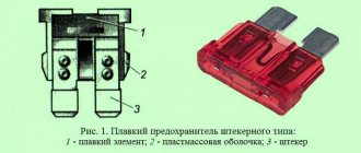
The relay and fuse box is also called the mounting block or black box. If problems are identified in the car related to electrical equipment, first check the fuses and relays. If they burn out, we replace them with the same ones, but first we must determine the cause of the burnout. The article contains a complete description of all Lada Largus mounting blocks.
Lada Largus fuse diagram
The first car of this VAZ family was released in 2011, and already in 2013 it became one of the leaders of the Russian car market, further consolidating its victory in 2014. Among the various options, the Largus Cross crossover is offered, which appeared in various trim levels in 2020 and 2020.
In 2017, it was announced the start of production of Lada Largus on gas, which was implemented in 2020, which also became the year of restyling of the family members. You can buy a car of the family with an 8-valve engine and a 16-valve engine. Unlike configurations, this does not greatly affect the set of fuses and relays that can be found in one of the two mounting blocks of the machine. The first and main one is located in the cabin, and the second is under the hood, which is quite typical for AvtoVAZ models.
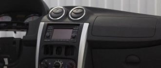
Fuse box of Lada Largus in the cabin
The mounting block in the cabin is considered the main one, so the vast majority of electrical circuit fuses are installed here. To be more precise, this block is located to the left of the dashboard, at its end and is covered with a plastic cover, the fastenings of which are clearly visible.
| Fuse no. | Current (amps) | Which electrical circuit does it protect? |
| F1 | 20 | Windshield wiper, windshield wiper switch, heated tailgate relay |
| F2 | 5 | Instrument cluster, fuel pump relay, engine control unit (ECU) |
| F3 | 10 | Brake light switch |
| F4 | 10 | Diagnostic connector, immobilizer antenna unit, body electrical monitoring system |
| F5 | — | Reserve (R) |
| F6 | — | (R) |
| F7 | — | (R) |
| F8 | — | (R) |
| F9 | 10 | Instrument cluster, low left headlight |
| F10 | 10 | Low right headlight |
| F11 | 10 | Instrument cluster, high left headlight |
| F12 | 10 | Far right headlight |
| F13 | 30 | Rear door window motors |
| F14 | 30 | Front door power window motors |
| F15 | 10 | Electronic control of ABS system, acceleration sensors, steering angle sensor |
| F16 | 15 | Electrically heated front seats |
| F17 | 15 | Sound signal |
| F18 | 10 | Left front and rear side lights |
| F19 F20 | 10 7,5 | Right front and rear side lights, glove compartment lights, instrument cluster lights, hazard warning switch, HVAC controls, audio system, cigarette lighter, central locking switch, front power window switches, license plate lights, right rear side lights . Rear fog light |
| F21 | 5 | Electrically heated exterior mirrors |
| F22 | — | Reserve (R) |
| F23 | — | (R) |
| F24 | (R) | |
| F25 | — | (R) |
| F26 | 5 | SRS system |
| F27 | 20 | Rear door wiper motor, horn, TDC sensor, reverse light switch |
| F28 | 15 | Control of interior electrical equipment (energy saving mode) |
| F29 | 15 | Interior electrical control, diagnostic connector |
| F30 | 20 | Interior electrical equipment control |
| F31 | 15 | Fog lights and their relays |
| F32 | 30 | Heated tailgate glass |
| F33 | — | |
| F34 | — | |
| F35 | — | |
| F36 | 30 | Electric motor for heating, air conditioning and ventilation systems |
| F37 | 5 | Electric exterior mirrors |
| F38 | 15 | Audio system, cigarette lighter |
| F39 | 10 | HVAC Motor Relay |
Purpose of fuses in the block installed in the passenger compartment
The internal fuse block is equipped with elements responsible for the systems:
- 1 – windshield cleaning device, heated rear window;
- 2 – tidy, ECU control relay for fuel pump, navigation device;
- 3 – stop button;
- 4 – turn signals and power supply to the diagnostic block, control of the size relay, parking module;
- 5-8 – reserve cells;
- 9 – low beam of the left headlight, assistance in controlling the tidy, pump for the headlight cleaning system;
- 10 – is fully responsible for the low beam of the right headlight;
- 11 – far left side and tidy;
- 12 – far right;
- 13/14 – section of rear/front power windows;
- 15 – ABS device and steering wheel rotation and acceleration sensors;
- 16 – electric heating of the rear sofa;
- 17 – beep;
- 18 – side lights of the left side, illumination of license plates, glove compartment;
- 19 – dimensions on the right side of the car, illumination of license plates, glove box, emergency lights, acoustics, switches;
- 20 – rear fog lamp on the left side, and part of the dashboard;
- 21 – rear view mirror shades;
- 22 – navigation system terminal;
- 23 – empty;
- 24 – EUR;
- 25 – power supply to the gas installation;
- 26 – seat belt pretensioner device, airbag electronics;
- 27 – belt position indicator for driver, front passenger, rear window wiper, windshield washer pump control;
- 28 – acoustic module, instrument and interior lighting;
- 29 – diagnostic block, UCH;
- 30 – central locking;
- 31 – front fog lights;
- 32 – heated rear wind window and exterior mirrors;
- 33-35 – empty nests;
- 36 – stove and air conditioner;
- 37 – mirror control drive;
- 38 – cigarette lighter and speakers;
- 39 – depends on the configuration – is responsible for the stove, air conditioning, navigation system.
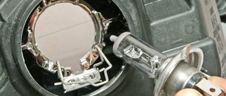
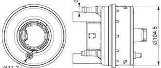
Heated rear window relay (interior)
Another important and often problematic device is the cabin relay for heating the stern door glass. The device is located in a niche behind the dashboard. To get there, you need to dismantle the panel and find the yellow cube on the red mount.
The module is removed from the socket quite simply and replaced with a similar one.
Fuses and relays Lada Largus
Cars considered were 2012, 2013, 2014 model years. Gasoline engines: 1.6 l 8V (K7M), 1.6 l 16V (K4M)
Where is the fuse and relay box located?
One in the mounting block under the hood - number 14 in the image.
To access the fuses and relays, press the side, rear and front fasteners and remove the cover.
Here is the block itself with the lid open.
Purpose of fuses and relays of the mounting block in the Largus engine compartment.
| Relay/fuse panel number | Relay/fuse number | Relay/fuse assignment |
| 299-1 | 231 (A) | Fog light relay |
| 753(B) | Headlight washer pump relay | |
| 299-2 | 233 | Heater Fan Relay |
| 597-1 | F1 (60 A), F2 (60 A) | Electronic control unit for ABS and ESP systems |
| 597-3 | F1 (50 A), F2 (25 A) | Exterior light switch, interior fuse box |
| 784 | 700 (A) | Cooling fan relay |
| 474 (B) | Air conditioning compressor relay | |
| 1047 | F1 (30 A), | Relay box power supply |
| F2 (25 A) | Injection relay power supply | |
| F3 (5 A) | Power supply for injection system relay, ECU | |
| F4 (15 A) | Not used | |
| 238 (A), | Injection blocking relay | |
| 236 (V) | Fuel pump relay |
Most fuses are installed in the fuse mounting block located in the passenger compartment, at the left end of the instrument panel, under a plastic cover.
To gain access you must remove the cover.
On the inside of the cover there is a diagram of the location of the fuses. The cover also contains spare fuses A of various current strengths and plastic tweezers B for removing fuses from the mounting block.
Decoding. Table.
| № | Current strength, A | Color | Protected circuit |
| F1 | 20 | Yellow | Windshield wiper, windshield wiper switch, heated tailgate relay |
| F2 | 5 | Beige | Instrument cluster, fuel pump relay, engine control unit (ECU) |
| F3 | 10 | Red | Brake light switch |
| F4 | 10 | Red | Diagnostic connector, immobilizer antenna unit, body electrical control unit |
| F5 | — | Reserve | |
| F6 | Reserve | ||
| F7 | Reserve | ||
| F8 | Reserve | ||
| F9 | 10 | Red | Instrument cluster, left low beam |
| F10 | 10 | Red | Low beam right headlight |
| F11 | 10 | Red | Instrument cluster, left high beam |
| F12 | 10 | Red | High beam right headlight |
| F13 | 30 | Green | Rear door window motors |
| F14 | 30 | Green | Front door power window motors |
| F15 | 10 | Red | ABS electronic control unit, acceleration sensors, steering angle sensor |
| F16 | 15 | Blue | Electrically heated front seats |
| F17 | 15 | Blue | Sound signal |
| F18 | 10 | Red | Left front and rear parking lights |
| F19 | 10 | Red | Right front and rear parking lights, glove compartment lighting, instrument cluster lighting, hazard warning switch, heating (air conditioning) and ventilation control unit, audio system, cigarette lighter , central locking switch, front door power window switches, license plate lights, right lights front and rear position lights |
| F20 | 7,5 | Brown | Rear fog light |
| F21 | 5 | Beige | Electrically heated exterior mirrors |
| F22 | — | Reserve | |
| F23 | — | — | Reserve |
| F24 | Reserve | ||
| F25 | — | Reserve | |
| F26 | 5 | Beige | SRS system |
| F27 | 20 | Yellow | Tailgate wiper motor, horn, TDC sensor, reverse light switch |
| F28 | 15 | Blue | Interior electrical control unit (energy saving mode) |
| F29 | 15 | Blue | Interior electrical control unit, diagnostic connector |
| F30 | 20 | Yellow | Interior electrical control unit |
| F31 | 15 | Blue | Fog lights, fog light relay |
| F32 | 30 | Green | Heated tailgate glass |
| F33 | — | — | Reserve |
| F34 | — | Reserve | |
| F35 | — | — | Reserve |
| F38 | 30 | Green | Electric motor for heating, air conditioning and ventilation systems |
| F37 | 5 | Beige | Electric exterior mirrors |
| F38 | 15 | Blue | Audio system, cigarette lighter fuse Lada Largus |
| F39 | 10 | Red | HVAC Motor Relay |
The heated tailgate glass relay is located under the instrument panel.
To replace the relay, remove the instrument cluster.
Lada Largus fuse diagram under the hood
The mounting block in vehicles of the Largus family serves as the location for all relays and part of the fuses. Of the latter, those that protect the circuits of the motor control system are presented. The fuses are marked with the letter F.
The block is located to the left of the battery. To get to it, press out the latches holding the cover on the side, back and front.
| Relay/fuse no. | Current (amps) | Relay/fuse assignment |
| 231(A). | Fog light relay | |
| 753(B) | Headlight washer pump relay | |
| 233 | Heater Fan Relay | |
| F1/F2 | 60 | Electronic control of ABS and ESP systems |
| F1/F2 | 50/25 | Exterior light switch, interior fuse box |
| 700(A), | Cooling fan relay | |
| 474(B) | Air conditioning compressor relay | |
| F1 | 30 | Relay box power supply |
| F2 | 25 | Injection relay power supply |
| F3 | 5 | Power supply for injection system relay, ECU |
| F4 | 15 | Not used |
| 238(A) | Injection blocking relay | |
| 236(B) | Fuel pump relay |
Purpose of relays and fuses in the mounting block located in the engine compartment
Each structural element of the mounting block is responsible for its own circuit or separate device.
Purpose of fuse links:
- 43 – power supply for HBO electrics;
- 44/45 – control of ABS units;
- 46 – power supply to the ignition switch;
- 47 – signal to the cabin fuses located after the ignition switch;
- 51 – fuel pump, ECM, ECU relay, head fan, ignition coil protection (depending on modification), phase distribution, canister and DC 1 purge;
- 52 – air conditioning system clutch, radiator head cooler.
Separately, you should consider the protective relays located in the block:
- 299/1 – fog lights and headlight washer;
- 299/2 – turning on the stove;
- 597/1 – control of ABS and ESP systems;
- 597/3 – external optics switch drive, power supply to the interior fuse box;
- 784 – control of activation of the radiator fan and air conditioner.
Fuse box in the engine compartment (VAZ 11189 (8 cells), 21129 (16 cells))
The second part of the electronic safety system is located under the hood. In the figure, the mounting block is indicated by the letter “B” and is hidden under a plastic cover. To open the panel, snap off the plastic clips or unscrew 4 screws (depending on the modification).
For the 8 and 16 valve versions, the placement of the platform is the same.
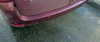
Returning the missing sound signal
| Author: sodium Published: 2061 days ago (March 11, 2015) Logbook: sodium Category: Treating sores Edited: 7 times - last March 13, 2015 | +9↑ Votes: 13 |
One day, the sound signal (horn) began to work every other time, a little later it was discovered that the operation and non- operation depended on the position of the headlight switch, and then the signal stopped working altogether. The Internet immediately suggested that this was a childhood sore.
The image has been reduced. Click to see original.
I won’t describe in detail how to remove the steering column cover, I’ll just tell you that you need a Torx screwdriver, I don’t remember what size and long enough. It turned out to be very difficult to get a screwdriver into the “star” of the screw, because it is located quite deep and at some unnatural angle that you don’t expect and poke somewhere past. After removing the casing, turn the steering wheel in the “9 o’clock” direction and unscrew the two screws securing the left steering column switch. Disconnect the wire block. We look at the switch block from the back and see this picture (almost like this, this photo was taken when everything was already fixed, we are interested in the red and black wires, mine was broken red) (see photo below) To be honest, I didn’t figure it out right away how the mechanism works, and soldered the broken wire to the thick solder point on the lever. But after that I didn’t check how the headlight control modes switch. It turned out that the neighbor seemed to be not turned on, the soldered wiring prevented the switch from being turned completely until there was a clear click. Well, soon the signal disappeared again, and I had to climb again. It turns out that when switching headlight modes, the inner rod to which the wires are connected rotates:
The image has been reduced. Click to see original.
The image has been reduced. Click to see original.
The image has been reduced. Click to see original.
Well, it’s understandable - the wires experience cyclic bending loads, the more often you switch the headlights. Now we disassemble the block to completely replace the wires (I changed both at once, without waiting for the second standard one to break). Unscrew the two screws on the block cover
The image has been reduced. Click to see original.
Cover - to the side
The image has been reduced. Click to see original.
Carefully pull the lever upwards from the switch housing
The image has been reduced. Click to see original.
The image has been reduced. Click to see original.
Now you need to remove the rotating part from the lever, which actually switches the headlights. We take a flat screwdriver, hold the lever into a fist, and act in the same way as many people open bottles - we rest the screwdriver, like a lever, against the base of the index finger, tighten the rotating part (it is held on the rod due to a tight fit)
The image has been reduced. Click to see original.
The image has been reduced. Click to see original.
The image has been reduced. Click to see original.
I also removed the horn button from the rotating part (it is held on by two latches)
The image has been reduced. Click to see original.
and it turned out that it was not in vain - one contact pad was burnt due to the fact that one contact on the rod was longer than the other. Well, and, of course, due to the fact that there is no relay in the sound signal control circuit, all the current passes through the button (a reason for thought for those who install more powerful signals)
The image has been reduced. Click to see original.
I cleaned the contact pad, did not grind the contact down - I tapped it, which caused it to flatten a little. Well, good - the contact area will be larger.
The image has been reduced. Click to see original.
The image has been reduced. Click to see original.
We pull the rod out of the lever, unsolder the wires from the switch block, unsolder the wires (or their “stubs”) from the rod. We are looking for wires of suitable diameter, because they must fit into the holes on the rod. If they fit, take pieces of wires of the required length. I took longer ones than the standard ones (in the first photos, where, in fact, everything is already ready, you can see that their stock is clearly larger) to reduce the influence of the breaking moment. We solder and wrap around the rod, placing it in the corresponding grooves and threading it through the corresponding holes.
The image has been reduced. Click to see original.
The image has been reduced. Click to see original.
The image has been reduced. Click to see original.
Further, during assembly, there is only one difficult moment - putting the rotating part back onto the rod. How I did it: inserted the rod into the lever, inserted the rotating part, placed the lever vertically on the table, took a bit screwdriver without the bit itself (you can use a small head or any hollow object of a suitable shape), and used it as a mandrel. Light blows on the screwdriver forced the rotating part into place
The image has been reduced. Click to see original.
Once the rod is installed, you can solder the wires to the contacts on the switch block. Assembly is carried out in reverse order. When installing the steering column cover, make sure that there are two things: 1. that the rubber boot on the lever is correctly oriented so that it can rotate around the lever. You will understand how to install it correctly in place. 2. so that the screws that were unscrewed at the very beginning get where they should be. This must be done before snapping the top part of the casing into place.
← Leather steering wheel
Create your own logbook, and you will be able to share with forum members your opinion about Largus, useful developments, installed additional information. equipment and tuning, trips and travel! To create a logbook, you must register on the site.
Tags: signal, disappeared, steering column switch, malfunction, horn, disappeared
Popular in in-flight magazines
DRL Traveling on Largus Fuel consumption Armrest Mileage Discs Radio To1 First impressions Buying Largus Electrics Covers for Largus Bumper net Modifications HBO Speakers Rear view camera Wipers Interior lighting Brake light Tuning Tires and wheels Check valve Tuning lights Noise insulation Winter tires Rugs Largus DVR Rki-19 Winter operation Roof box PTF Tail lights Izhevsk Car audio Injectors Mudguards Washer reservoir Hood stops Low beam lamp Installing a cabin filter Parking sensors Thresholds Lada Largus LED Carpet covers Floating idle speed Trunk lighting Tinting Trunk shelf Trip to the sea Hood seal Accident Owner's review Fender liners Walkie Talkie Additional Socket Eyeglass case Replacement 5th gear
Comments (2)
| Vitaly March 12, 2020 at 03:58 pm 0 | |
|
| 4elowe4e April 5, 2020 at 8:16 pm 0 | |
|
| Add a comment | RSS comments feed |
Additional comments: