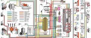
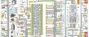
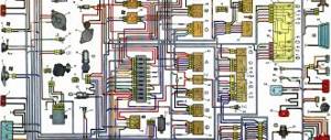
To enlarge the wiring diagram, click on the image below.
- block headlights
- side direction indicators
- accumulator battery
- starter relay
- carburetor electro-pneumatic valve
- carburetor microswitch
- generator 37.3701
- gearmotors for headlight cleaners *
- Fan motor switch sensor
- engine cooling fan motor
- sound signals
- distributor
- spark plug
- starter
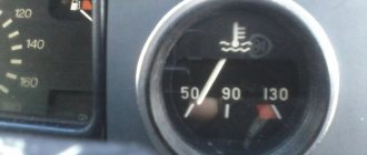
- coolant temperature gauge sensor
- engine compartment lamp
- low oil pressure warning sensor
- low brake fluid level indicator sensor
- windshield wiper motor
- carburetor electro-pneumatic valve control unit
- ignition coil
- headlight washer pump motor *
- windshield washer pump motor
- mounting block
- windshield wiper relay
- hazard warning and direction indicator relay
- brake light switch
- reverse light switch
- ignition relay
- ignition switch
- three lever switch
- hazard switch
- socket for portable lamp**
- heater fan switch
- additional resistor for the electric motor of the heater (stove)
- rear window heating indicator lamp
- low brake fluid level warning lamp
- signaling unit
- heater fan electric motor
- glove compartment lamp
- light switches on the front door pillars
- switches for warning lights of open front doors ***
- front door open warning lights ***
- connection block
- cigarette lighter
- watch
- instrument light switch
- diode for checking the serviceability of the low brake fluid level indicator lamp
- fuel level indicator
- fuel reserve indicator lamp
- speedometer
- turn signal indicator lamp
- carburetor choke indicator lamp
- battery charge indicator lamp
- carburetor choke warning switch
- instrument cluster
- econometrician
- light switches on the rear door pillars
- coolant temperature gauge
- tachometer
- indicator light for parking brake (handbrake)
- low oil pressure warning lamp
- high beam indicator lamp
- indicator lamp for turning on external lighting
- voltmeter
- parking brake indicator switch ("handbrake")
- outdoor light switch
- rear window heating switch with backlight
- rear fog light switch with on/off indicator *
- fog light circuit fuse
- lampshade ****
- tail lights
- level indicator and fuel reserve sensor
- connectors for connecting to the rear window heating element *
- license plate lights
In order to download the VAZ 2107 diagram and save it to your computer, hover over the image above, then right-click and select “save as image” (size about 300 kilobytes).
The image resolution is 1600×872 pixels, so the electrical circuit can be easily printed on a printer and used when repairing a car.
The order of conditional numbering of plugs in blocks:
- a - headlight units, headlight and windshield wipers, windshield wiper relay, carburetor solenoid valve control unit
- b - mounting block and three-lever switch
- c - hazard warning and direction indicator relay
- d — rear lights (numbering of pins in order from the edge of the board)
- d - hazard warning switch
Additional information "asterisks":
* — Installed on parts of manufactured cars.
** — Not installed since 2000.
*** - Not installed since 1998.
**** — Since 2000, instead of one lamp on the roof, two lamps have been installed on the door pillars.
Car diagram - Zhiguli 2107
Connection diagram of the mounting block on the VAZ 2107
P1 — relay for turning on the heated rear window; P2 - relay for turning on the headlight cleaners and washer; P3 - relay for turning on sound signals; P4 - relay for switching on the electric motor of the engine cooling system fan; P5 - headlight high beam relay; P6 - low beam headlight relay; A - the order of conditional numbering of plugs in the mounting block blocks. The outer number with the letter “Ш” in the plug designation is the block number, and the inner number is the conventional number of the plug. The plugs of the blocks without color marking are conventionally shown in brown
Mounting block, without cover
1 — relay for turning on the heated rear window (P1); 2 — relay for turning on the headlight cleaners and washer (P2); 3 - relay for turning on sound signals (P3); 4 — relay for switching on the electric motor of the engine cooling system fan (P4); 5 - spare fuse; 6 — relay for turning on the high beam headlights (P5); 7 — relay for low beam headlights (P6); 8 - fuse
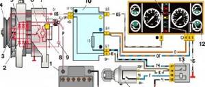
Generator system connection diagram 37.3701
1 - battery; 2 - negative diode; 3 - additional diode; 4 - generator; 5 - positive diode; 6 - stator winding; 7 - voltage regulator; 8 — rotor winding; 9 — capacitor for suppressing radio interference; 10 — mounting block; 11 — battery charge indicator lamp in the instrument cluster; 12 - voltmeter; 13 — ignition relay; 14 - ignition switch
Connection diagram of the G-222 generator system
1 - generator; 2 - negative diode; 3 - positive diode; 4 - stator winding; 5 - voltage regulator; 6 – rotor winding; 7 – capacitor for suppressing radio interference; 8 - battery; 9 — battery charge warning lamp relay; 10 — mounting block; 11 — battery charge indicator lamp in the instrument cluster; 12 - voltmeter; 13 — ignition relay; 14 - ignition switch
Electrical diagram of starter connections
1 – generator; 2 – battery; 3 – shunt coil of the stator winding; 4 – starter; 5 – serial stator winding coil; 6 – holding winding of the traction relay; 7 – pull-in winding of the traction relay; 8 – starter activation relay; 9 – mounting block; 10 – ignition switch
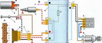
Diagram of a classic and contactless ignition system
1 — spark plugs; 2 — ignition distributor; 3 - capacitor; 4 — breaker cam; 5 - ignition coil; 6 — mounting block; 7 - ignition relay; 8 — ignition switch; A - to terminal “30” of the generator
1 — spark plugs; 2 — ignition distributor sensor; 3 — screen; 4 - contactless sensor; 5 - switch; 6 – ignition coil; 7 — mounting block; 8 - ignition relay; 9 — ignition switch; A - to terminal “30” of the generator
Turning on external lighting - diagram
1 — block headlights with side light lamps; 2 — engine compartment lamp; 3 — mounting block; 4 — glove box lighting lamp; 5 — instrument lighting switch; 6 — rear lights with side light lamps; 7 — license plate lights; 8 — external lighting switch; 9 — indicator lamp for external lighting, located in the speedometer; 10 — ignition switch; A - to terminal “30” of the generator; B - to instrument lighting lamps and switch backlight lamps
Turning on the headlights and fog lights in the rear lights - electrical diagram
1 — block headlights; 2 — mounting block; 3 - headlight switch in a three-lever switch; 4 — external lighting switch; 5 — rear fog light switch; 6 — rear lights; 7 - rear fog light circuit fuse; 8 — fog light indicator lamp, located in the indicator lamp block; 9 — indicator lamp for high beam headlights, located in the speedometer; 10 — ignition switch; P5 - headlight high beam relay; P6 - relay for turning on the low beam headlights. A - view of the headlight plug connector: 1 - low beam plug; 2 — high beam plug; 3 — ground plug; 4 — side light plug; B - to terminal “30” of the generator. B – terminals of the rear light printed circuit board (numbering of terminals from the edge of the board): 1 - to ground; 2 - to the brake light lamp; 3 - to the side light lamp; 4 - to the fog light lamp; 5 - to the reversing lamp; 6 - to the turn signal lamp
This is interesting: Carburetor cleaning fluid
Pinout of the new instrument cluster (with econometer)
Here, everything is the other way around - there is no oil pressure indicator (instead there is an econometer), instead of a brake fluid level lamp there is a suction lamp (or an engine management system lamp on injectors), and instead of a fog lamp lamp there is an oil pressure lamp.
White 6-terminal block X1:
- Gasoline level sensor
- Turn signal indicator lamp
- Battery charge sensor (voltmeter -)
- Gasoline level warning lamp
- Overall plus (+)
- Battery charge sensor (voltmeter +)
White 8 terminal block X2:
- Dimensions indicator lamp
- High beam warning lamp
- Oil pressure warning lamp
- My dash is empty, but there is a terminal in the wiring that goes to the brake fluid level sensor
- Battery charge indicator lamp
- Indicator lamp for the air damper (choke) or engine control unit for injectors
- Empty
- Parking brake warning lamp (handbrake)
Orange 6-terminal block X3:
- General minus (-)
- Tachometer (if this contact is empty, then the tachometer is on pin #4)
- Instrument lighting
- Empty, and if not empty - to the tachometer
- Empty
- Coolant temperature sensor
I decided not to show the colors of the wires here, so as not to completely confuse anyone, because the colors are generally different in all circuits