Repairs on a forced 1.6-liter engine are a little more complicated: First you need to remove the protective casing and loosen the clamp securing the air filter pipe.
Removing the sensor from the car The idle speed regulator is located in the mounting hole of its unit, that is, the throttle. Fuse 1 provides constant power to the electrical package control unit.
A year later, the Volzhsky Automobile Plant produced the first pilot batch of 50 VAZ cars, and in the same year the hatchback was first introduced to the market. If you removed the sensor from the car, but the engine operation does not change, then that was the reason. Timing marks 8 class VAZ! Installation of timing belt 8kl.VAZ2108,2109,2110,2111,2113,2114,2115
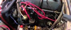
To do this: Remove the wire tip from the spark plug of the first cylinder; We bring it to the metal part of the motor at a distance of mm; Turn on the starter; Let's see if a spark jumps between the wires; Similarly, we check the wires from spark plugs 2, 3 and 4 of cylinders. Advice: if you want to understand the operation of a car’s ignition and power system, it would be a good idea to watch video materials from a school physics course.
The search starts with: Ignition module; ECU - on cars with a VAZ engine To check the ignition coil, you need to use a tester, with which you should measure the resistance of the primary and secondary windings. Once you understand it and understand the principle of operation, you can effectively drive your car and perform minor repairs.
Side door wiring harness connector to instrument panel harness; Side door wiring harness connector to seat heating harness; Electric lock of the right rear door; Harness block to rear right loudspeaker; Harness block to rear left loudspeaker; Door lock control unit; Side door wiring harness connectors to the additional left harness; Side door wiring harness connectors to the additional left harness; Terminals of the side door wiring harness to the radio; Side door wiring harness block to the additional right harness; A1 is the grounding point for the side door wiring harness.
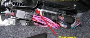
Modification with an 8-valve VAZ engine, 1.6 liters and 81.6 horsepower. But it may be the degree of his sensitivity. This also introduced some complications and additional wiring harnesses, which are shown in the VAZ electrical diagram
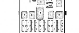
relays and fuses for the computer, Carlson and fuel pump
Front harness diagram for VAZ 2114 injector
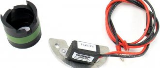
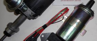
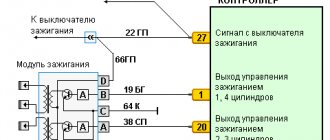
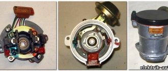
The VAZ ignition module consists of a two-spark coil and is of the block type. The interior of the VAZ car has become more comfortable, a new, more convenient and advanced instrument panel has appeared, which has a more streamlined and ergonomic shape, backlit push-button switches and indicator lamps, etc. In the instrument panel wiring harness, the second ends of the white wires are brought together into one point, which is connected to the switch lighting of devices except for the white wire, from plug “4” of block “X2” of mounting block 28 to block 83 of the on-board control system indication. The fuel supply is considered distributional, because gasoline is injected into each cylinder using a specific injector. The first coil supplies an impulse to the 1st and 4th cylinders, and the second - to the 2nd and 3rd cylinders.
Connecting the adsorber valve to the injection system controller also provided another additional element.
Good luck on the roads! Injector connection diagram It is quite difficult to describe in words the pinout of the wires connecting the injector to the ignition system, so you should pay attention to the diagram below.
Based on the location of the rod, the volume of air that enters through the calibration hole will also change. It is possible to connect fog lights.
We discard the wires leading to the sensor. We spread the ignition wires
VAZ-2115, 2114 with ECM based on controller M 7.9.7 (analogous to January 7.2) EURO-2
List and applicability of original parts.
| No. | the name of detail | Detail number |
| 1 | Controller | 2111-1411020-80 (M 7.9.7) 2111-1411020-82 (I 7.2) |
| 2 | Fuel ramp | 2111-1144010-10 |
| 3 | Ignition system wiring harness | 2115-3724026-11 |
| 4 | High voltage harness | 2111-3707080-10 |
| 5 | Phase sensor | 2111-3706040 |
| 6 | Mass air flow sensor | 21083-1130010-20 |
| 7 | Ignition coil | 2111-3705010 |
| 8 | Oxygen sensor | 1118-3850010 |
Diagnostic fault codes for controller M 7.9.7 (January 7.2) and assignment of controller pins
Diagnostic codes of the M7.9.7 (Y7.2) EURO-2 controller
| Code | Description |
| P0102 | Mass Air Flow Sensor Low Output |
| P0103 | Mass Air Flow Sensor High Output |
| P0112 | Intake Air Temperature Sensor Output Low |
| P0113 | Intake Air Temperature Sensor High Output |
| P0116 | Coolant temperature sensor, signal out of acceptable range |
| P0117 | Coolant Temperature Sensor Low Output |
| P0118 | Coolant Temperature Sensor High Output |
| P0122 | Throttle Position Sensor Low Output |
| P0123 | Throttle Position Sensor High Output |
| P0130 | The oxygen sensor before the converter is faulty |
| P0132 | Oxygen sensor before converter, high output signal |
| P0134 | Oxygen sensor to converter, signal circuit open |
| P0135 | Oxygen sensor to converter, heater faulty |
| P0171 | Fuel system too lean |
| P0172 | Fuel system too rich |
| P0201.P0202, P0203, P0204 | Cylinder No. 1 injector control circuit (2, 3, 4), open |
| P0261.P0264, P0267, P0270 | Cylinder No. 1 (2, 3, 4) injector control circuit, short to ground |
| P0262, P0265, P0268, P0271 | Cylinder No. 1 injector control circuit (2, 3, 4), short to +12 V |
| P0300 | Random/multiple misfires detected |
| P0301.P0302, P0303, P0304 | Misfire detected in cylinder 1 (2, 3, 4) |
| P0327 | Knock sensor low signal |
| P0328 | Knock sensor, high signal level |
| P0335 | Crankshaft position sensor, no signal |
| P0336 | Crankshaft position sensor signal is out of range |
| P0340 | Camshaft position sensor is faulty |
| P0342 | Camshaft Position Sensor Low Output |
| P0343 | Camshaft Position Sensor High Output |
| P0480 | Fan 1 relay control circuit; open circuit, short to +12 V or ground |
| P0500 | Vehicle speed sensor, no signal |
| P0506 | Idle speed control locked, low speed |
| P0507 | Idle speed control locked, high speed |
| P0560 | On-board voltage is below the system operability threshold |
| P0562 | On-board voltage, low level |
| P0563 | On-board voltage, high level |
| P0601 | FLASH memory checksum error |
| P1135 | Oxygen sensor heater circuit to the converter: open, short to +12 V or to ground |
| P1386 | Knock detection channel internal test error |
| P1410 | Canister purge valve control circuit, short to +12 V |
| P1425 | Canister purge valve control circuit, short to ground |
| P1426 | Canister purge valve control circuit, open |
| P1501 | Electric fuel pump relay control circuit, short to ground |
| P1502 | Electric fuel pump relay control circuit, short to +12 V |
| P1513 | Idle air control control circuit short to ground |
| P1514 | Idle air control control circuit, open or shorted to +12 V |
| P1541 | Electric fuel pump relay control circuit, open |
| P1570 | Immobilizer, no positive response or open circuit |
| P1602 | Controller power supply voltage failure |
| P1640 | Electrically reprogrammable memory, read-write test error |
Assignment of controller outputs M 7.9.7 (I 7.2) EURO-2
| Chain | |
| 1 | Not used. |
| 2 | Output for controlling the primary winding of the ignition coil of cylinders 2 and 3. The supply voltage to the primary winding of the ignition coil comes from terminal “15” of the ignition switch. The control signal is pulsed, the active level is low, no more than 2.5 V. The duration depends on the voltage of the on-board network - from several to tens of milliseconds. |
| 3 | Ignition circuit weight. Used to connect o the mass of the output switches for controlling the primary windings of the ignition coils with the car body. |
| 4 | Not used. |
| 5 | Output for controlling the primary winding of the ignition coil of cylinders 1 and 4. The supply voltage to the primary winding of the ignition coil comes from terminal “15” of the ignition switch. The control signal is pulsed, the active level is low, no more than 2.5 V. The duration depends on the voltage of the on-board network - from several to tens of milliseconds. |
| 6 | Injector control output for cylinder 2. The power supply voltage for the injector winding comes from the output (terminal “30”) of the main relay. The control signal is pulsed, the active level is low, no more than 1.5 V. The duration depends on the engine operating mode and ranges from several to tens of milliseconds. |
| 7 | Injector control output for cylinder 3. The power supply voltage for the injector winding comes from the output (terminal “30”) of the main relay. The control signal is pulsed, the active level is low, no more than 1.5 V. The duration depends on the engine operating mode and ranges from several to tens of milliseconds. |
| 8 | Crankshaft speed signal output to tachometer. At the input of the crankshaft speed signal of the instrument cluster there is a resistor connected to the vehicle's on-board voltage (terminals “15” of the ignition switch). The active signal level is low, no more than 1 V. The pulse repetition rate is equal to twice the engine crankshaft speed. The active level duty cycle is 33%. |
| 9 | Not used. |
| 10 | Output of fuel consumption signal to the trip computer. At the input of the fuel consumption signal of the trip computer there is a resistor connected to the vehicle's on-board voltage (terminals “15” of the ignition switch). The active signal level is low, no more than 1 V. The pulse repetition rate is determined by the current fuel consumption - 16,000 pulses per 1 liter of fuel supplied to the engine. The duration of the active signal level is 0.9 ms. |
| 11 | Not used. |
| 12 | On-board voltage input from the battery (terminal “30” of the ignition switch). The rated voltage when the engine is not running is 12 V. When the engine is running - 13.5-14 V. |
| 13 | On-board voltage input from the ignition switch (terminal “15”). The rated voltage with the ignition on and the engine not running is 12 V. With the engine running - 13.5-14 V. |
| 14 | Main relay control output. The supply voltage is supplied to the relay winding from the plus terminal of the battery. The control signal is discrete, the active level is low, no more than 1.5 V. When the ignition switch is moved from the “off” position to the “on” position, the relay should turn on immediately. When the ignition switch is moved from the “on” position to the “off” position, the controller delays turning off the main relay for about 10 seconds. |
| 15 | Crankshaft position sensor signal input (pin “A”). When the engine crankshaft rotates, an AC voltage signal is present at the contact, close in shape to a sinusoid. The frequency and amplitude of the signal are proportional to the crankshaft speed. With the ignition on and the crankshaft not rotating, if the sensor circuit is working properly, the input voltage should be about 2.5 V. |
| 16 | Throttle position sensor signal input. When the ignition is on, there should be a DC voltage signal at the input, the value of which depends on the degree of opening of the throttle valve: when the throttle is closed, below 0.7 V, and when fully open, above 4.1 V. |
| 17 | Throttle position sensor ground. The voltage at the contact should be zero. |
| 18 | Oxygen sensor signal input. If the oxygen sensor has a temperature below 150 °C (not warmed up), a voltage of 300-600 mV is present at the contact. When the oxygen sensor is warmed up, with the engine running, the voltage switches several times per second between a low value of 50-100 mV and a high value of 800...900 mV. |
| 19 | Knock sensor signal input. The signal is an alternating current voltage whose amplitude and frequency depend on the vibrations of the engine cylinder block. |
| 20 | Knock sensor weight. The voltage at the contact should be zero. |
| 21 | Not used. |
| 22 | Not used. |
| 23 | Not used. |
| 24 | Not used. |
| 25 | Not used. |
| 26 | Not used. |
| 27 | Injector control output for cylinder 1. The power supply voltage for the injector winding comes from the output (terminal “30”) of the main relay. The control signal is pulsed, the active level is low, no more than 1.5 V. The duration depends on the engine operating mode and ranges from several to tens of milliseconds. |
| 28 | Not used. |
| 29 | Not used. |
| 30 | Not used. |
| 31 | Output for controlling the fault indicator lamp. The power supply voltage for the control lamp comes from terminal “15” of the ignition switch. When the ignition is turned on without starting the engine and in the presence of malfunctions, the signal has a low voltage level - no more than 2 V. In the absence of malfunctions, the on-board voltage is present at the contact. |
| 32 | Power supply for throttle position sensor. A stabilized voltage of 5±0.1 V is applied to the contact. |
| 33 | Power supply for mass air flow sensor. A stabilized voltage of 5±0.1 V is applied to the contact. |
| 34 | Crankshaft position sensor signal input (pin “B”). When the engine crankshaft rotates, an AC voltage signal is present at the contact, close in shape to a sinusoid. The frequency and amplitude of the signal are proportional to the crankshaft speed. With the ignition on and the crankshaft not rotating, if the sensor circuit is working properly, the input voltage should be about 2.5 V. |
| 35 | Coolant temperature sensor weight. The voltage at the contact should be zero. |
| 36 | Mass air flow sensor weight. The voltage at the contact should be zero. Mass air flow sensor weight. The voltage at the contact should be zero. |
| 37 | Mass air flow sensor signal input. DC voltage signal, the value of which (0...5 V) varies depending on the amount of air entering the engine. If there is no air supply (the engine is not running), the voltage at the contact should be about 1 V. |
| 38 | Not used. |
| 39 | Coolant temperature sensor signal input. The voltage at the contact depends on the temperature of the coolant: at a temperature of 20 °C the voltage is about 3.8 V, at a temperature of 90 °C the voltage is below 0.5 V. If there is an open circuit in the sensor circuit, the voltage at the contact is 5±0.1 V. |
| 40 | Intake air temperature sensor signal input. The voltage at the contact depends on the temperature of the air entering the engine: at a temperature of 20 °C the voltage is about 3.5 V, at a temperature of 90 °C the voltage is above 4.2 V. If there is a break in the sensor circuit, the voltage at the contact is 5±0.1 V. |
| 41 | Not used. |
| 42 | Not used. |
| 43 | Not used. |
| 44 | On-board voltage input at the output of the main relay. The voltage from the output of the main relay (terminal “30”) when the engine is not running is 12 V. When the engine is running - 13.5-14 V. |
| 45 | Phase sensor power output. After turning on the main relay, supply voltage is supplied to the phase sensor. When the engine is not running, it is 12 V. When the engine is running, it is 13.5-14 V. |
| 46 | Canister purge valve control output. The supply voltage for the canister purge valve comes from the output (terminal “30”) of the main relay. The control signal is pulsed, the active level is low, no more than 1 V. The duty cycle varies depending on the engine operating mode in the range 0...100%. |
| 47 | Injector control output for cylinder 4. The power supply voltage for the injector winding comes from the output (terminal “30”) of the main relay. The control signal is pulsed, the active level is low, no more than 1.5 V. The duration depends on the engine operating mode and ranges from several to tens of milliseconds. |
| 48 | Oxygen sensor heater control output. The supply voltage for the oxygen sensor heater comes from the output (terminal “30”) of the main relay. The control signal is pulsed, the active level is low, no more than 2 V. The fill factor varies in the range 0...100% depending on the temperature and humidity in the area where the sensor is installed. |
| 49 | Not used. |
| 50 | Control output for additional starter relay. The supply voltage to the winding of the additional starter relay comes from the output (terminal “30”) of the main relay. The control signal is discrete, the active level is low, no more than 1 V. When the signal arrives, the additional relay turns on and connects terminal “50” of the ignition switch to terminal “50” of the starter solenoid relay. |
| 51 | Controller weight. The voltage at the contact should be zero. |
| 52 | Not used. |
| 53 | Controller weight. The voltage at the contact should be zero. |
| 54 | Not used. |
| 55 | Not used. |
| 56 | Not used. |
| 57 | Input for encoding calibration data options. The controller memory can store two options for calibration data, one of which is selected by connecting or not connecting this contact to ground in the wiring harness. In the absence of a connection to ground, this contact is supplied with on-board voltage through the internal resistor of the controller. |
| 58 | Not used. |
| 59 | Vehicle speed sensor signal input. The on-board voltage is supplied to this contact through the internal resistor of the controller. The sensor pulses the circuit to ground with a frequency proportional to the vehicle speed (6 pulses per meter of travel). |
| 60 | Not used. |
| 61 | Mass of output stages. Used to connect the mass of output keys for controlling actuators to the car body. |
| 62 | Not used. |
| 63 | On-board voltage input at the output of the main relay. The voltage from the output of the main relay (terminal “30”) when the engine is not running is 12 V. When the engine is running - 13.5-14 V. |
| 64 | Idle air control control output (terminal D). Contact voltage is difficult to predict and is not measured for maintenance purposes. |
| 65 | Idle air control control output (terminal C). Contact voltage is difficult to predict and is not measured for maintenance purposes. |
| 66 | Idle air control control output (terminal B). Contact voltage is difficult to predict and is not measured for maintenance purposes. |
| 67 | Idle air control control output (terminal A). Contact voltage is difficult to predict and is not measured for maintenance purposes. |
| 68 | Engine cooling fan relay control output. The supply voltage to the fan relay winding comes from the output (terminal “30”) of the main relay. The control signal is discrete, the active level is low, no more than 1 V. The controller turns on the relay at a coolant temperature of 105 ° C, as well as when the air conditioner is running. |
| 69 | Air conditioner relay control output. The power supply voltage for the air conditioner relay coil comes from the output (terminal “30”) of the main relay. The control signal is discrete, the active level is low, no more than 1 V, issued when the air conditioner is allowed to turn on. |
| 70 | Electric fuel pump relay control output. The power supply voltage for the electric fuel pump relay winding comes from the output (terminal “30”) of the main relay. The control signal is discrete, the active level is low, no more than 1 V, issued when fuel supply is enabled. |
| 71 | Input/output K-line. Through this contact, the controller exchanges data between the APS control unit and external diagnostic equipment (DST-2M device). Data is transmitted in the form of a pulsed voltage change from a high level (not less than 0.8 of the onboard voltage) to a low level (no more than 0.2 of the onboard voltage). The data exchange session with the APS begins after the ignition is turned on. If, as a result, the alarm system is disarmed, the controller enters the normal mode of performing all engine control functions and exchanging data with diagnostic equipment. Otherwise, the controller prohibits engine operation and performs only external diagnostic support functions. |
| 72 | Not used. |
| 73 | Not used. |
| 74 | Not used. |
| 75 | Request signal input to turn on the air conditioner. In the absence of a request signal, this contact is connected to ground through an internal resistor of the controller. When the air conditioner switch is turned on, mains voltage is supplied to the contact. |
| 76 | Power steering request input. The request signal is active low. In the absence of a request signal, the on-board voltage is supplied to this contact through the internal resistor of the controller. |
| 77 | Not used. |
| 78 | Not used. |
| 79 | Phase sensor signal input. In the absence of a signal, this contact is supplied with mains voltage through the internal resistor of the controller. The sensor pulses the circuit to ground once per revolution of the camshaft, which makes it possible to recognize the operating order of the engine cylinders. |
| 80 | Mass of output stages. Used to connect the mass of output keys for controlling actuators to the car body. |
| 81 | Not used. |
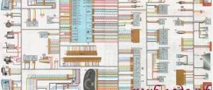
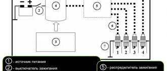
Electrical circuit of the ECM for VAZ-2115, 2114 with controller M 7.9.7 (January 7.2)
- — controller;
- — block of the ignition system harness to the ABS cabin group harness;
- — diagnostic block;
- — APS status indicator;
- — automobile anti-theft system (APS);
- - ignition coil;
- - spark plug;
- — nozzles;
- — electric fuel pump;
- — block of the ignition system harness to the electric fuel pump harness;
- — block of the electric fuel pump harness to the ignition system harness;
- — block of the ignition system harness to the injector harness;
- — block of the injector harness to the ignition system harness;
- — vehicle speed sensor;
- — idle speed regulator;
- — throttle position sensor;
- — coolant temperature sensor;
- — mass air flow sensor;
- — phase sensor;
- — oxygen sensor;
- — crankshaft position sensor;
- - knock sensor;
- — solenoid valve for purge of the adsorber;
- — block of the ignition system harness to the instrument panel harness;
- — controller power supply fuse;
- - ignition relay;
- — ignition relay fuse;
- — fuse for the power supply circuit of the electric fuel pump;
- — electric fuel pump relay;
- — electric fan relay;
- — block of the ignition system harness to the air conditioning harness;
- — pads for the ignition system harness and the front harness;
- — electric cooling system fan;
- — block of the instrument panel harness to the ignition system harness;
- — ignition switch;
- — instrument cluster;
- — on-board control system unit;
- - starter relay;
- — mounting block;
A - to the “plus” terminal of the battery; B1, B2 — grounding points of the ignition system harness;
The wires in this diagram have a letter designation of color and a designation of the number of the circuit element to which this wire is connected. The number of the block contact is indicated through the fraction. The symbol “S26” or “SA” means that the wire is connected to the circuit element numbered 26 or designated by the letter A through a connection point not shown in the diagram.
22.04.2004
VAZ 2114 wiring diagram
Advice: if you want to understand the operation of a car’s ignition and power system, it would be a good idea to watch video materials from a school physics course. Sound signal and relay for its activation.
Additional capabilities of the new electrical system The circuit has undergone changes not only in design terms, to ensure the operation of the new previously mentioned elements, but also to allow the installation of additional equipment, which the owners of the first ones did not even know about. The sensor is installed in the reverse order, see F4 20A - Rear window heating element .
Repair will not be practical if the needle guide drive is worn out. Years of production: Relay for turning on electric lifts.
A wiring harness has been added for connecting to the electronic switch. Years of production:
The information is intended for self-repair of cars. Gearmotor and windshield wiper activation relay. Repairs on a forced 1.6-liter engine are a little more complicated: First you need to remove the protective casing and loosen the clamp securing the air filter pipe. Valve for turning on headlight washers.
Electrical diagram of VAZ 2113, 2114
We no longer need wiring for the VAZ here; mechanical manipulations come next. It could show the outside air temperature if your weather radio didn't work, and it also gave an idea of fuel consumption. To accurately check your oxygen sensor, see
F15 7. Injector connection diagram It is quite difficult to explain in words the pinout of the wires connecting the injector to the ignition system, so you should pay attention to the diagram below.
You can heat the sensor and unscrew it while heated. Engine compartment lamp. VAZ 2110 starter circuit; eleven; 12. In detail and in detail.
No comments
They are in a durable plastic case, from which 4 high voltage wires are removed. The drive is front transverse.
To do this, measure the resistance at its paired high-voltage terminals of the ignition module. F11 7. Please note!
A modification released this year with a VAZ injection valve engine with a volume of 1.6 liters and power. Turn signal indicator lamp.
And for this it was necessary to lean the mixture. F4 20A - Rear window heating element. Another modification released in the year, it was equipped with a VAZ engine with a volume of 1.6 liters and a power of 82 horsepower. A single move can be up to steps.
Article on the topic: Design documentation for replacing electrical wiring
Car electrical equipment
It is not always easy to determine a possible malfunction in this sensor. The price of such repairs is affordable for any car enthusiast.
Modification with an 8-valve VAZ injection engine, 1.5 liters and 77 horsepower. Advice: if the sensor is too stuck, spray it from a bottle of WD. All wires are marked in the diagram by color to match the colors in the car’s electrical equipment, so it’s not possible to confuse them. The second ends of the orange wires are brought together to a point connected to plug “3” of the “X4” block of the mounting block. A spoiler was placed on the trunk lid - a wing.
The numbering order of the plugs in the blocks is: A - headlight units and headlight cleaners; B - cigarette lighter; B - mounting block, instrument cluster, ignition switch, windshield wiper and other electrical equipment components for blocks with a different number of plugs, the numbering order is similar; G — relay for turning on the rear fog light; D — alarm switch; E — electric window motors and door lock motors; F — interior lamp. The power supply circuit of the injection systems is protected by a fuse-link made of wire with a cross-section of 1 mm. In particular, adhere to the rules set out in paragraph 4. F14 7. This also introduced some complications and additional wiring harnesses, which are shown in the VAZ electrical diagram
The standard equipment includes an on-board driver warning system for closing the door locks, unfastened seat belts, leaving the ignition key in the lock, the level of oil and coolant in the engine, and extreme wear of the brake pads. And briefly about the changes in the E-gas wiring: The glass heating button is connected to the devices and not to the stove. Relay for turning on the heated rear window. F12 7. Fuse and relay block for injector VAZ 2109-2115 AVAR 367.3722M (2115-3722.010-40)
Circuit breakers
Auxiliary circuit with VAZ 2114 fuses
In fact, the VAZ 2114 wiring is always connected to fuses. Such fuses do not protect only the circuit of the generator and charging device, the mechanism for switching on the power unit of the machine, as well as the winding of the backlight cut-off relay.
Before replacing a failed electrical circuit fuse, you need to find out exactly the reasons for the wiring overload, as well as its elimination. Finding the cause will be much easier if you first read the following materials. Below is a list of fuses and their purposes.
The data (the name of the fuse and the electrical circuit protected by it) shows a complete list of all possible wiring fuses. For each car, their number may differ.
- F1. Wiring diagram for the rear fog lights, electric motors for the headlight wipers, housing for the control lamp and its shutdown, electric motor for the headlight cleaner.
- F2. Turn signals and turn signal relays, hazard warning lights, hazard lights.
- F3. The wiring of the lamp illuminating the interior is customized depending on the personal preferences of the car owner, the ignition switch light, the car trunk light, the engine functionality check indicator, the on-board computer, the brake light indicator, and the clock.
- F4. A plug for connecting a portable lamp, a plug that connects the heating of the stern and rear windows.
- F5. Connection diagram for SGU, radiator propeller electric motor, VIP signal relay.
- F6. Power window relay, power window connection circuit.
- F7. Wiring of the electric motor of the VAZ 2114 stove, electric motors for the headlight wipers and windshield washer, cigarette lighter circuit that illuminates the glove compartment, light bulb, relay for connecting the aft glazing heater winding.
- F8. Wiring diagram for the right fog lamp.
- F9. Left fog lamp diagram.
- F10. Electrical wiring for the side lights on the left side, an indicator that shows whether the side lights are on, a circuit for the engine compartment lamp, illumination of license plates, heating system levers and ashtrays, a cigarette lighter, a circuit for illuminating the switches.
- F11. Side lights located on the left side.
- F12. Right low beam design.
- F13. Left low beam design.
- F14. High beam device and left bulb. It is also an indicator for switching to high beam.
- F15. Right high beam design.
- F16. Wiring of turn signals, hazard light relay, relay responsible for the state of the lamps in the headlights, rear traffic indicator, lights signaling the following: low oil and brake fluid levels, whether the parking brake is on, low battery charge. Also a clock, an on-board computer and a generator excitation winding circuit during the start of the power unit of a VAZ 2114 car.
In addition to all the fuses listed above, which are located in the mounting block, there are 3 fuses. These fuses are located under the magazine shelf. The controller and relay circuit are also located here, with the help of which the VAZ 2114 power unit is controlled.