Gamma GF 115T computer for VAZ 2115 (Lada Samara 2) and VAZ 2109 (Lada Samara)
Price when ordering in the online store.
If you live in Samara and want to purchase goods in an online store, then you will need to place an order by selecting the Delivery Method “Courier in Samara”.
The price at which the product is sold in a retail store at the address: Samara, st. Partizanskaya, 56a, shopping center "Cascade", office 206.
If the retail store price is not indicated, then the retail store sells the product at the online store price.
This is the status of the product, displaying information about the availability of the product in the warehouse.
This product is in stock at the store and will be sent to you as soon as possible without pre-ordering.
This item is currently out of stock, but we are awaiting availability from the manufacturer. Once the item arrives in the store, it will be shipped to you.
The operator will inform you when the goods arrive at the store.
This product is not in stock at the store, but we can bring it especially for you if you place an order.
Products supplied “to order” are shipped only with 100% prepayment.
The operator will inform you about the delivery time.
Description of the trip computer Gamma GF 115T
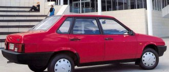
The route on-board computer Gamma GF 115T is the first model of on-board computer for VAZ 2113-14-15 and VAZ 2108-09-099 cars from the manufacturer Ferrum-Group.
The next models of the BK series for cars of the Lada Samara and Lada Samara 2 family are the Gamma GF 215T, Gamma GF 315T and Gamma GF 415T computers.
The GF 115T on-board computer is installed in a specially designated place for the trip computer, which is found in all of the above vehicles. The GF 115T is made in a black case and is equipped with a two-line text display with either blue or green backlighting. The bookmaker is controlled using 4 buttons, which are located to the left and right of the display. Text indicator 16 characters 2 lines optimized for viewing angle.
The GF 115T is easy to connect, thanks to the detailed connection and operating instructions included with the product. Lada Samara 2 cars already have a ready-made chip for connecting the trip computer, which means for the BC to fully function, it is necessary to connect another K-line wire to the diagnostic block to read data from the controller (ECU).
The GF 115T is equipped with the following set of functions:
- diagnostic parameters: searching, decoding and deleting system errors, recognizing the controller version, etc.
- route parameters: average speed for the trip, instantaneous fuel consumption, average fuel consumption, forecast of mileage on remaining fuel, amount of fuel in the tank, trip time and much more.
- The alarm will always warn you in time about dangerous on-board voltage, low engine oil level, exceeding the set speed limit, dangerous coolant temperature, etc.
- Maintenance dates will pleasantly tell you when to change the engine oil, gearbox oil, brake pads, timing belt and more.
Compared to other BCs, the GF 115T is distinguished by the absence of a speech informant, but benefits from high reliability, ease of use and reasonable price. Gamma on-board computers are of good quality for a reasonable price. This means that by choosing the GF 115T for your car, you are purchasing a reliable assistant for every day.
Designed for installation on
- VAZ 2113, VAZ 2114, VAZ 2115 Lada Samara 2
- VAZ 2108, VAZ 2109, VAZ 21099 Lada Samara
Gamma GF 115T is compatible with controllers
- BOSCH M1.5.4/MP7.0/M7.9.7/
- January 5.1/VS 5.1/7.2/M7.3(Euro-3), Intelma, Avtel.
Functionality:
Trip computer:
- remaining fuel in the tank
- fuel mileage forecast
- total fuel consumption
- fuel consumption per trip
- distance traveled during the trip
- average fuel consumption per trip
- digital speedometer
- average speed per trip
- "black box" in speed
- travel time and cost
Motor tester:
- Instant fuel consumption
- Coolant temperature
- Onboard voltage
- Engine speed
- Throttle position
- Mass air flow
- Ignition timing
- Idle air control position
- Gas pedal position (for E-gas)
- Ionizer
Multi-display:
On-screen overview of 3 multi-displays:
- route parameters
- motor tester
- organizer
Sports screen:
- achieved driving speed
- acceleration time to 100 km/h
- time of passage of the measuring section
- maximum speed achieved during acceleration
Controller diagnostics:
- determination of injection system controller type and firmware number
- injection system diagnostic codes with error decoding
- erasing errors from the controller memory
- clearing controller RAM
Alarm signal:
- Dangerous engine overheating
- Unacceptable on-board voltage
- Exceeding the speed and rpm threshold
Reminders about:
- the need to change the engine oil
- need to change gearbox oil
- need to replace spark plugs
- need to replace the air filter
- need to replace the fuel filter
- need to replace the timing belt
- need to replace the alternator belt
Organizer:
- Watch
- Calendar
- Alarm
- Air temperature
Specifications:
LCD display monochrome double-sided
Operating supply voltage range, V 8 - 16
Average power consumption current, no more, mA:
- with backlight on 150
- with ignition off 12
1.15.5 On-board computer
1.15.5. On-board computer
| GENERAL INFORMATION |
| The Opel on-board computer informs you about driving parameters, which it periodically records and analyzes electronically. |
When you press the buttons, the following functional fields are displayed on the display, a number of them in abbreviated form:
– Momentanverbrauch (current fuel consumption); – Durchschnittsverbrauch (average fuel consumption); – Durchschnittsgeschwindigkeit (average speed); – Reichweite (estimated mileage before refueling); – Stoppuhr (stopwatch); – Aussentemperatur (outside temperature).
Control via two buttons on the wiper arm
| Button “S” – selection (press until the desired field appears). Button “R” – erasing (when functional fields appear): – average fuel consumption; – average speed of movement by pressing the “R” button (at least 2 seconds) they are simultaneously displayed. |
The data previously recorded in the memory will be automatically erased and the stopwatch will be reset at the same time.
Indelible data:
Current fuel consumption, estimated mileage before refueling and outside temperature.
| When the receiver is turned on, 5 seconds after turning on the computer (key “S”), the receiver indication appears again in the top line of the display. |
If the radio is switched off, both lines of the display will show the functions of the on-board computer.
In any case, control check messages have priority.
The inclusion of the computer field is registered by the appearance of the inscription “TRIP” at the bottom left of the display.
Fault indication
The message "F" indicates a malfunction. The field containing the fault is blocked. Contact an authorized Opel workshop.
Current fuel consumption
The display changes depending on the speed:
Display in l/h below 13 km/h (Display in gph below 8 mph) Display in l/100 km above 13 km/h (Display in m/gal above 8 mph) Display 0 l/100 km when traction is turned off (Indicated 999.9 m/gal when traction is turned off)
Average fuel consumption
| The calculation of average fuel consumption can be started at any time, for example, after refueling. Reset is performed by pressing the “R” key. |
Display in l/100 km (Display in miles/gallon)
average speed
| The calculation of the average speed can be started again at any time, for example, after the start of movement. Reset is performed by pressing the “R” button. |
Interruptions in movement with the ignition turned off are not taken into account in the calculation.
Display in km/h (display in mph)
Remaining mileage over 50 km
| The remaining mileage is calculated based on the current fullness of the tank and average fuel consumption over the last 20–30 km of travel. |
After refueling, a new remaining mileage value can be calculated by pressing the "R" key, or this value is automatically recalculated after approx.
10 km. Display in km (Display in miles)
Remaining mileage less than 50 km
| The indication appears without using the “S” button to call up the “Calculated remaining mileage before refueling” function if there is less than 50 km of fuel left in the fuel tank. The indicator flashes. |
When calling another function field, this warning function is disabled. Repeated automatic switching to “Calculated remaining mileage before refueling” occurs after stopping movement.
Display in km (Display in miles)
Stopwatch
| When you press the “R” button, zero–start–stop–zero… Activating the stopwatch does not affect the function fields: – average fuel consumption; - average speed. |
Outside temperature
| When the temperature drops, the indicator reacts immediately; when the temperature rises, it reacts with a delay. |
Warning:
If the temperature is a few degrees above 0° C (32° F), the road may already be icy.
At temperatures below 3° C, the display automatically switches to “outside temperature”. If you call another function field, this warning function is disabled.
Display in ° C (Display in ° F)
Transcript
1 Route on-board computer GAMMA GF115T On-board computer GAMMA GF115T (hereinafter referred to as BC) is designed for installation on injection VAZ cars of the Lada-Samara, Lada-Samara-2 family. The BC is compatible with serial firmware of BOSCH M1.5.4 / MP7.0 / M7.9.7 / January 5.1 / VS 5.1 / January 7.2 “Itelma” / “Avtel” controllers. The BC performs the functions of a clock with a calendar and an alarm clock, a thermometer, a trip computer, a diagnostic tester and an alarm and determines the timing of maintenance and the dynamic parameters of the car. Installed on the instrument panel of model 2114, installation on a high panel is possible. Functions of the on-board computer Clock and thermometer - clock with calendar and alarm clock - air temperature outside the car Maintenance - changing the engine oil - changing the gearbox oil - replacing spark plugs - replacing the air filter - replacing the fuel filter - replacing the timing belt Trip computer - remaining fuel in the tank - fuel mileage forecast - total fuel consumption - fuel consumption per trip - distance traveled per trip - average fuel consumption per trip - digital speedometer - average speed per trip - speed black box - trip time - trip cost Diagnostic tester - current (instantaneous) fuel consumption - coolant temperature - on-board voltage - engine speed - throttle position - air mass flow - ignition timing - idle air control position - ionizer
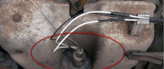
2 Dynamic parameters - achieved driving speed - acceleration time to 100 km/h - time to pass the measuring section System errors - diagnostic codes of the injection system with a full interpretation of the error codes and the ability to reset them Alarm indicator - dangerous engine overheating - unacceptable voltage in the on-board network - excess speed threshold Equipment on-board computer. 1 temperature sensor. 1 diagnostic line adapter. 1 manual. 1 package. 1 Technical characteristics Supply voltage, V Average current consumption, ma - with the backlight on and the ignition off. 20 Clock accuracy, s/day. ± 10 External temperature measurement accuracy, C. ± 1 External temperature measurement range, C Operating temperature, C Weight, g no more than Installation Disconnect the negative terminal from the battery. 1. Pass a single wire K - line to the diagnostic block, which is located at the bottom of the console under the decorative trim and connect it to socket M (see Fig. 1) on one side and to the reserve contact 2 of the trip computer block Fig. 1 2. Install the BC instead of the standard plug in the instrument panel, having previously connected it to the trip computer connector.
3 3. When installing the BC on the 83 (high) panel (see Fig. 2), the corresponding wires should be connected to receive signals from the FLS, DSA and SRT in accordance with the existing technical documentation for the vehicle’s electrical equipment. Remove the visor of the instrument cluster and unscrew the screws securing the combination. Stretch the pink wire from the BC block on the right and rear of the car radio to the instrument cluster. Disconnect the white (13-terminal) block from the instrument cluster. Remove the 11th contact with the pink wire from the block and connect the FLS wire into the gap of the removed contact. Contacts: 1. Fuel consumption signal (FLS) 2. K - line 3. Ignition 4. Reserve B 6. Backlight 7. Ground 8. Fuel level sensor (FLS) 9. Speed sensor (DSA) 10. Temperature sensor 11. Sensor temperature Next, connect the BC in accordance with Fig. 2. The 4-terminal block is located inside the console in the area of the car radio socket. The 8th terminal block is located next to the diagnostic block under the glove shelf. 4. To install the temperature sensor, you need to pass the temperature sensor wire from the installation location of the BC to the left front bumper mounting bracket (under the hood through the rubber seal of the speedometer cable through the wiring harness into the hole in the front frame to the left front bumper mounting bracket). Unscrew the bumper mounting nut (10mm wrench) and install the sensor on the stud (above the washer), tighten the nut. Connect the temperature sensor connector to the BC and install the BC in its original place. Connect the negative terminal to the battery. Turning on the BC When you first connect the BC to the vehicle's on-board network and turn on the ignition switch, the following is determined: - controller type and software version - the communication channel between the BC and the fuel injection controller (K-line) is tested. In this case, the display shows, for example: On-board computer GAMMA, then the controller type and software version are determined: January 5.1 Software code: J5V05L19. The communication channel is tested, if not present, a warning message is displayed: No communication (in this case, the Current parameters and System errors groups are excluded from the BC operation menu). If the connection is present, the warning message does not appear. Note: to retest during operation, after turning on the ignition switch, briefly press the Mode Select button. TIME MENU The purpose of the buttons is to switch to the “Clock and thermometer” group and select the functions of this group according to the scheme: multi-display - clock - alarm clock - calendar - outside temperature; — switching between modes according to the following scheme: trip computer — diagnostic tester — system errors — maintenance — dynamic parameters; UP-DOWN - selection of functions in the modes of a trip computer, diagnostic tester, maintenance, viewing system errors, etc.
Description - BC GAMMA GF 115T (discontinued)
The GF115T on-board computer is installed in a specially designated place for the trip computer, which is found in all of the above vehicles.
The GF 115T is made in a black case and is equipped with a two-line text display with either blue or green backlighting.
The on-board computer is controlled using 4 buttons located to the left and right of the display.
The GF 115T is quite easy to connect, especially thanks to the detailed connection and operating instructions that come with the product.
Lada Samara 2 cars already have a ready-made chip for connecting a trip computer, which means for the BC to fully function, it will also be necessary to connect the K-line wire to the diagnostic block to read data from the controller (ECU).
Purpose of the trip computer GAMMA GF115T
The trip on-board computer GF115T is designed to monitor the technical condition of cars produced by OJSC AVTOVAZ of the Lada Samara and Lada Samara-2 family (VAZ 2109, 21099, 2113, 2114, 2115). Installed in the standard socket of the instrument panel and is compatible with Electronic Engine Control System (ECM) controllers: BOSCH M.1.5.4/ MP7.0/ M7.9.7/ ME17.9.7JAN5.1/ VS 5.1/ 7.2/ M 73 EURO 3/ M74.
Functions of the GAMMA GF115T on-board computer:
- multi display;
- remaining fuel in the tank;
- mileage forecast on remaining fuel;
- total fuel consumption;
- fuel consumption per trip;
- distance traveled during the trip;
- average fuel consumption per trip;
- digital speedometer;
- average speed per trip;
- “black box” in speed;
- travel time and cost.
- multi display;
- instant fuel consumption;
- cool temperature liquids;
- on-board voltage;
- engine shaft rotation speed;
- throttle position;
- mass air flow;
- ignition timing;
- idle air control position;
- throttle pedal position (for E-gas);
- ionizer
- watch;
- calendar;
- alarm;
- multi display;
- air temperature.
- oil change (internal combustion engine and gearbox);
- replacing spark plugs;
- replacing the timing belt;
- replacing the air filter;
- replacing the fuel filter.
- maximum speed per trip;
- acceleration time to 100 km/h;
- time of passage of the measuring section.
- about the manufacturer;
- about the on-board computer;
- about the ECM;
- about the car (service book).
- dangerous overheating of the internal combustion engine;
- unacceptable voltage of the on-board network;
- exceeding the speed threshold;
- exceeding the rpm threshold.
overview on the screen of 3 multi-displays:
- route parameters;
- motor tester;
- organizer
- diagnostic codes of the ECM with a complete decoding of the codes and the ability to collect them.
- calculation of cost by mileage, consumption, time.
CONSUMER ANALYSIS
INSTALLATION:
installation of the OMEGA GABARIT on-board (trip) computer does not cause any complications if you follow the well-written instructions. Moreover, most of the time will be spent installing the temperature sensor, which should be located under the front bumper of the car.
CONTROL:
The OMEGA GABARIT on-board computer is controlled using four buttons, which are functionally divided into two groups. In the first group there is only one key, which is responsible for switching between the following parameters: clock, calendar, alarm clock, thermometer, bookmaker information, demo mode. The second group has more buttons, but not much - only three. The central one took responsibility for switching between groups: trip computer, diagnostic tester, engine management system errors, maintenance reminders. The side keys are accordingly required to scroll through the parameters within each group.
Controlling the on-board computer is quite logical and does not cause any difficulties. For example, changing a parameter is done by simultaneously pressing two arrow keys. After the parameter value has been changed using the same keys, you must press the buttons simultaneously again so that the changes are made to the computer’s memory.
OPERATING MODES AND
FUNCTIONALITY:
as mentioned above, all the functionality of the OMEGA GABARIT on-board computer is thematically divided into several groups. The following parameters are concentrated in the “Trip computer” group: remaining fuel in the tank, total fuel consumption for the trip, trip consumption, mileage for the trip, average fuel consumption for the trip, average trip speed, travel time, display “city”, display “ track." In addition, this menu item provides a “black box” function, which makes it possible to demonstrate the maximum speed for the last 60 seconds. Perhaps it will appeal to those who like to tickle their nerves in a dispute with traffic police officers.
In the “Diagnostic tester” group you can monitor the values of such parameters as: current vehicle speed, coolant temperature, on-board voltage, crankshaft speed, throttle position, mass air flow, ignition timing, idle air control position, type controller and software version, instantaneous fuel consumption, setting the temperature for turning on the cooling fan. This group also includes two quite interesting modes: “Plasmer” and “Winter Launch”. The first mode carries out pre-heating of the spark plugs to facilitate engine starting at negative ambient temperatures. The second mode is necessary for automatic activation of the “Plasmer” function after turning on the ignition. In addition, in this mode, the cooling system fan is switched on briefly, which is necessary to warm up the electrolyte in the battery. The latter, in turn, will greatly facilitate engine starting.