The famous “loaf” - the multi-purpose UAZ 452 appeared in the line of the Ulyanovsk Automobile Plant back in 1965 and remains on the assembly line to this day. Of course, over the years of production, the manufacturer has modernized the car in every possible way - the suspension, engine, and wiring diagram of the UAZ 452 have changed, but in general, the entire design has remained the same.
Electrical wiring of UAZ 452: reliable single-wire circuit
Differences between electrical systems
Modernizations affected the service conditions of cars of different years of production.
The car does not cause any particular difficulties when carrying out routine maintenance with your own hands, however, the electrical systems have differences, the reasons for which were:
- Modifications of power units;
- Changes to the instrument panel;
- Installations of lighting and side lights of a new generation.
Read also the article “Wiring Moskvich 2140: two cars under one index.”
Original photo of the 1974 model documentation included with the car
Central and foot light switches
How does the central light switch work?
The central light switch (Fig. 120, a) is designed to turn on headlights, sidelights, rear lights, and instrument panel lighting.
Fig. 120. Central light switch: a – device; b – clamps; c – diagram.
It consists of a housing 2 in which a contact plate 9 with a spring 10 is installed, connected to a movable carriage 5. The carriage is mounted on a driver 12 connected to the rod 1 and is fixed by a ball 13 loaded with a spring 11. The housing is closed from above by a contact panel 6 with a clamp 7 and contacts 8. A panel 3 with a clamp 4 is attached to the body, in which there is a rheostat 16 with a slider 15 attached to the rod 1, and an insulator 14. The body is secured with a nut to the instrument panel panel.
The switch terminals are numbered (Fig. 120, c). The battery wire is connected to terminal 3; to the terminal 1 wire from the foot light switch; to clamp 2 – sidelights; 4 – headlight lamps (high beam); 5 – instrument panel lighting lamps; 6 – one of the side clamps of the foot switch. The rod has three fixed positions, in each of which the contact plate 9 connects the contacts of the clamps to each other in specified combinations (Fig. 120, b): I – the rod is pushed in all the way – the consumers are turned off; II – the rod is extended to half – the sidelights, taillights and instrument panel lighting are turned on (for ZIL-130); sidelights or low beam headlights depending on the position of the foot switch (GAZ-53A, GAZ-24 “Volga”), rear lights and instrument panel lighting, and for the GAZ-24 “Volga” the license plate light; III – the rod is extended all the way – the headlights are turned on (low or high beam depending on the position of the foot switch), rear lights, instrument panel lighting, and for the GAZ-24 Volga, license plate lighting. The brightness of the instrument panel lighting is adjusted by a rheostat by turning the handle of rod 1.
What is the purpose of a foot switch, how does it work and how does it work?
The foot light switch (Fig. 121) allows you to turn on the sidelights or low beam headlights in position II of the central switch, and in position III, switch the headlights from high to low beam, and vice versa. It consists (Fig. 121, a) of a housing 11, a plastic cover 2 with fixed contacts 1,4,5 and clamps 3 for connecting wires, a pusher 12 with a button 14 and a return spring 13, a ratchet wheel 9 and a movable contact 6, installed on axis 10. The movable contact 6 is fixed on a textolite disk 7, connected by means of a groove to the tooth of the ratchet wheel 9, and spring 8 is pressed against the fixed contacts.
Fig. 121. Foot light switch: a – device; b – low beam; c – high beam.
Each time you press button 14, pusher 12 with protrusion “a” rotates ratchet wheel 9 by 60°. The moving contact alternately closes contacts 1 and 5 (Fig. 121, c) or contacts 4 and 5 (Fig. 121, b) and thereby turns on the low or high beam headlights. When the high beam is on, the warning lamp on the instrument panel lights up.
*** Test your knowledge and answer test questions on the topic “Lighting devices”
switch, light, central foot light switch
See also:
avtomobil-1.ru
Period from 1965 to 1984
During this period, the automaker equipped its products with electrical components available to the domestic industry. Some of them were known for a long time, others were experimental, as evidenced by videos from previous years, and which had to prove their suitability.
Connection diagram for headlights on UAZ 452 first editions
Lighting control
In particular, the controls and a number of main units migrated from its predecessor, the GAZ-69. Thanks to this, the price of the car remained the same.
On models of the first years of production, a foot light switch was installed, which had several operating modes:
- The first position activated the circuit for switching the low beam headlights and side lights;
- In the second position, the low and high beam headlight circuit was activated.
For reference: Turning on the headlights (low or high beam) led to the turning off of the front side lights.
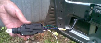
Foot switch for headlights and parking lights
The modernized light switch has a different operating algorithm:
- The first position supplies power to the side lights only;
- The second position is side lights and low (high) beam headlights.
Caution: This algorithm with non-switchable dimensions is a mandatory requirement for passing MOT. The factory instructions give recommendations for reworking the old circuit, in which it is important not to mix up the contacts of the foot switch.
The most correct option is to replace the old switch with a modern one, which uses only 3 contact groups.
Also, on older versions of the “452” there was no alarm, so in the electrical diagram:
- An RS-57 breaker relay was installed (mounted in the wiring gap from the “+” terminal of the battery to the direction indicator switch);
- The middle contact of the relay closed the indicator light on the instrument panel.
See also the Ural motorcycle wiring diagram.
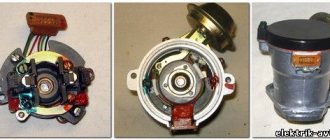
Ignition system
Ignition of UAZ 452 model 1968
Also on the “452” contact ignition was installed:
- The “+” wire from the battery supplied power to the ignition coil;
- From the coil, the high-voltage wire transmitted the impulse to the breaker (distributor) and further to the spark plugs.
Meet UAZ 452
The car was a cargo-passenger version of an off-road vehicle with a 4x4 wheel arrangement. The Ulyanovsk Automobile Plant mastered production of the model back in 1965.
You can evaluate its capabilities by watching the following video:
The UAZ 452 is capable of transporting cargo weighing up to 700 kg in the back. In addition, it can tow a trailer weighing 850 kg. The vehicle became very popular not only in Russian off-road conditions, but was also successfully used in large cities in various capacities (pictured in the article).
In particular:
- Like a traffic police car;
- As a fire engine;
- Ambulance car;
- Grocery store;
- Utility vehicle, etc.
The famous Barefoot on the basis of UAZ 452 - a road train in the Izmailovo Central Park of Culture and Culture
Electronic components
The electrical wiring of the UAZ 452 was a simple single-wire circuit.
Structurally, it had the following solutions:
- The role of the second wire was played by the metal body and the components and assemblies attached to it;
- All electronic components and actuators had a “-” displayed on the housing. The cost of such a solution justified the imperfection of the scheme.
Central and foot light switch of UAZ-452, brake light switch and sound signal.
To control the sidelights and headlights, switch between high and low beam headlights, on vehicles of the UAZ-452 family, the central light switch P38 and the foot light switch P39 are used. The brake light is turned on using the VK12 switch.
Central light switch P38.
Turning on the lamps to indicate the dimensions of the car and switching the headlights is done by a central switch of type P38, which has three positions: position I - all lighting is off; position II - the rear marker lights are on and, depending on the position of the foot light switch, the sidelights or low beam in the headlights are on; position III - the rear marker lights are on and, depending on the position of the foot light switch, the high or low beam in the headlights is on.
In positions II and III of the central switch, the instrument lighting lamps, as well as special (sanitary) and license plate lamps, are turned on. When the high beams are turned on, the indicator lamp located in the speedometer lights up in the headlights.
Foot light switch P39.
The switching of sidelights to low beam headlights in position II of the central light switch, and low beam headlights to high beam in position III of the central light switch, is carried out by a foot-operated light switch type P39. The switch is installed on the sloping floor of the cab under the driver's left foot. The headlights are switched by pressing the foot on the switch plunger.
Compressing the spring, the plunger with the help of the rod rotates the ratchet, which drags along the insulating washer with the contact plate and closes the terminals located on the contact panel in the required sequence.
A protective rubber seal prevents water and dirt from entering the switch. During operation, it is necessary to monitor the condition of the rubber seal and prevent water from entering the switch. It is not recommended to disassemble the switch.
Brake light switch VK12.
To turn on the brake light lamps, a VK12 switch was introduced into the hydraulic brake system. When the pressure in the brake system increases above 3.5 kgf/cm2, the diaphragm bends so much that the contact plate, overcoming the resistance of the spring, closes the switching contacts, as a result of which the electrical circuit is closed, through which current is supplied to the brake light lamp. It is not recommended to disassemble the switch.
Sound signal C44.
Cars are equipped with a C44 sound signal. The signal is two-wire and is activated by pressing a button located in the center of the steering wheel. When you press the signal switch button, a current begins to flow through the electromagnet winding, creating a magnetic flux.
The electromagnet attracts an armature, which bends the membrane and simultaneously presses the spring of the moving contact and the breaker away from the fixed contact. In this case, the circuit opens, the current in the coil and the electromagnetic flow stops, and the armature, under the action of the membrane and the centering flat spring of the membrane rod, returns to its original position.
After this, the contacts close again and the described process is repeated until the signal button is pressed. A capacitor connected in parallel with the contacts serves to reduce sparking between the contacts.
Adjustment and troubleshooting of the C44 sound signal.
The sound strength of the signal is regulated by an adjusting screw, the head of which is located on the rear wall of the housing. The sound signal does not require special care during operation. It must be remembered that the signal cannot be turned on for a long time, since it is designed for short-term operation.
If there is no signal sound, it is necessary to check the fuse through which the sound signal is connected to the circuit, and the reliability of the connection of the signal circuit wires. If, when you press the button, the signal does not sound and the fuse blows, this indicates sintering of the signal contacts or a breakdown of the insulating plate of the moving contact.
The signal produces a rattling sound when the signal is loosened to the bracket, when the resonator or armature is loosened, when cracks appear in the membrane, as well as when the signal adjustment is disrupted. In this case, loose connections must be tightened, the cracked membrane must be replaced, and the misregulated signal must be adjusted with the adjusting screw.
The signal turns on intermittently if there is poor contact in the signal button with ground or the wires are loose at the terminals of the signal circuit. If the signal sounds weak when the engine is idle or running at low speed, but sounds normal when the engine is running at medium speed, this indicates a low battery. In this case, you need to charge or replace the battery.
auto.kombat.com.ua
Wiring diagram for injection UAZ (loaf) – Auto mechanic
It would not be an exaggeration to call the legendary model “452” the ancestor of a whole family of multi-purpose utility vehicles under the UAZ brand. This is true, and experts are well aware that the wiring diagram of the UAZ 3962, components and transmissions of the model 3904, as well as other modifications, are unified with the “452”.
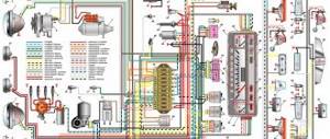
UAZ wiring diagram with conventional steering column switches
All world manufacturers of passenger cars and utility vehicles are developing in a similar way:
- A successful design serves as the basis for a whole family of cars;
- Constant refinement and modernization allows us to update the model range;
- Unification of parts and components reduces the cost of creating new cars.
The famous “Polbaton” - photo of the UAZ 3904 model
For reference: When car owners communicate with each other about the “civilian” version of a particular UAZ unit, this is true. Initially, “452” was created by order of the Ministry of Defense as a vehicle accompanying tank columns on the march. And for use on public roads, the car was modernized.
Find out also about the features of replacing UAZ 3303 wiring.
Platform for conveyor models
The “Loaf”, which became famous, thanks to its all-metal body, the “452” model served as a platform for the creation of an entire line of vehicles:
- UAZ 2206 – a minibus designed for 11 people;
- UAZ 3962 – vehicle for emergency medical services;
- UAZ 396255 - a civilian modification of an ambulance for the needs of rural areas;
- UAZ 39099 – promoted under the name “Farmer”. Designed for 6 passengers and 450 kg of cargo;
- UAZ 3741 – a van for transporting 2 passengers and 850 kg of cargo;
- UAZ 3303 – an onboard vehicle with an open body;
- UAZ 3904 is a cargo-passenger version that combines the convenience of an all-metal body for passengers and an open body for cargo.
For reference: in all modifications, the electrical wiring of the UAZ 2206 is taken as a basis, from which, for each model, unused components that perform certain functions in the car interior have been removed.
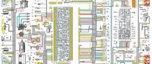
The electrical wiring of the UAZ 3909 is identical to the models 3741, 2206 and 3962
Features of the modification with multifunctional control
Variations with the car body did not greatly affect its technical equipment. But when changes affected the governing bodies, they underwent modernization:
- Interior wiring for UAZ;
- Steering column control unit for turns and exterior lighting;
- Control unit for the operation of electric windshield wipers on the instrument panel.
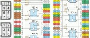
Electrical circuit diagram of a UAZ vehicle equipped with a multifunction steering column switch
Reason for modernization
For reference: according to pan-European safety requirements, when activating light and sound devices while driving, the driver of the vehicle must not remove his hands from the steering wheel. Based on this principle, the wiring diagram for the VAZ 2112 and other models of the Tolyatti Automobile Plant is built.
Old style instrument panel
On cars of the UAZ family, the windshield wiper control unit was located on the instrument panel. And since this did not meet safety requirements, then on all subsequent modifications:
- it was replaced with a more modern multifunctional unit located directly on the steering wheel;
- They began installing a new instrument panel.
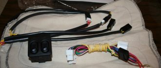
New steering wheel switch cluster with new instrument panel
Self-upgrade
Cars of new releases already have a multifunctional control unit in the database. But owners of early editions can re-equip the car with their own hands to meet modern safety requirements.
To do this you will need:
- Original UAZ 2206 wiring - as the most suitable for self-conversion;
- Factory instruction diagram that allows you to correctly connect the steering column switches to the standard diagram;
- Desire to make high-quality installation.
Diagram of a conventional wiper control unit
Advice: the cost of doing it yourself is low, so you should not neglect it when operating UAZ vehicles in dynamic road conditions - on city highways or public roads. As a matter of fact, independently replacing the UAZ wiring on older models will also eliminate its failures.
The work algorithm will be as follows:
- Disconnect the battery;
- We remove the control unit from the instrument panel;
- We disconnect the wires, checking their compliance with the factory diagram in Fig. 1;
- Remove the standard switches from the steering wheel column.
To remodel, you will need to purchase several new parts:
- Block of multifunctional steering column switches from the UAZ 390995 model;
- Relay for the windshield wiper circuit (the VAZ model is best suited, as is wiring 2112, connecting the relay and the switch block);
- Contact blocks in the amount of 3 pieces (one 8-pin for the side of the steering column switches and two 6-pin for the relay and standard adapter).
See also the UAZ 31512 wiring diagram.
New connection diagram for older versions of cars
Advice: a good help for any alteration of the electrical circuit can be the video on the pages of our website, which is shared by car owners who independently service their cars.
Multi-function switch installation process
Let's start installation:
- We replace the standard connector with a new one;
- We cut the 4x4 wire (in Fig. 2 indicated by a red cross);
- We connect its ends to 31V and to the S contact of the windshield wiper relay;
- We connect wire 5-2 to pin 15 of the wiper relay;
- Contact J of the relay is connected to the 2nd contact of the steering column switch;
- We connect the 13-pin relay to ground;
- We connect the new terminal block with an adapter cable;
- We connect it to the block, which was previously connected to the standard switch on the instrument panel;
- We close the contacts of the windshield washer electric motor to contacts 6 and 7 of the switch;
- On the relay, connect pin 86 to pin 6 of the steering column switch.
UAZ 31512 wiring diagram: electrical equipment features
Car owners who have not previously encountered domestic off-road versions are always confused by two, at first glance, different names for the same model. In particular, if you need a wiring diagram for a UAZ 31512, then you should look for documentation for the “459B” model of the Ulyanovsk Automobile Plant, since this is the same vehicle.
The electrical circuit of the UAZ 31512 is identical to the UAZ 459B
Two names for one model
The thing is that from 1945 to 1966 there was an industry classification of vehicles, according to which:
- Each car plant was assigned a code consisting of capital letters of the full name;
- Car factories were assigned a certain digital range, which they could use for the models they produced.
For reference: the Ulyanovsk Automobile Plant has been assigned the letter code UAZ, and the range is from 400 to 499. Accordingly, all models produced and advertised in the video must be designated in this way.
See also the UAZ 31514 wiring diagram.
New requirements
When a new classification of vehicles was adopted in 1966 (industry standard - OH 025270-66), the essence of which was to standardize digital designations, the process of replacing the names of existing vehicles turned out to be quite complicated:
- Due to the impossibility of simultaneously replacing all documentation;
- Due to the mentality of producers and consumers, therefore, the replacement process lasted more than 30 years.
Index decoding
The civilian version of the car “459B”, according to the new classification, received the digital index 31512, where:
- The first digit indicates the vehicle class, determined by engine displacement and vehicle weight. In relation to the model, this is the number “3” weighing up to 1.5 tons and working volume up to 2.5 liters;
- The second digit of the index indicates the type of vehicle. Number “1” – passenger car;
- The third and fourth digits of the index are assigned by the automaker. As a rule, they indicate an in-plant designation;
- The fifth digit indicates the modification. In this case, UAZ modified the “459” model, which, according to the new requirements, should be numbered as 3151. Accordingly, the modified car receives the index 31512.
Instructions for deciphering the industry standard OH 025270-66
And since the vehicle is produced and operated much longer than this period, the wiring diagram of the UAZ 31512 is identical to “459B”.
Caution: in the process of modernizing cars, designers almost always make changes to electrical circuits. Accordingly, the electrical wiring of the UAZ 31512 will differ from the previous version. This must be taken into account when servicing or replacing it.