Replacing the cylinder head gasket for VAZ “OKA” 1111 1988-2008
- Repair manuals
- VAZ "OKA" 1111 1988-2008
- Replacing the cylinder head gasket
If a leak of engine oil or coolant is detected at the junction of the cylinder head with the cylinder block, remove the head and replace its gasket.
A leak can also occur due to warping of the block head due to overheating. You will need:
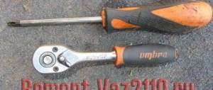
Torque wrench, hexagons “5” and “10”, keys “10”, “13” and “17”, screwdriver.
| WARNING The head gasket is a one-time use, so each time the head is removed, the gasket must be replaced. |
| 1. Disconnect the wire from the “–” terminal of the battery. |
| 2. Set the piston of the 1st cylinder to the TDC position of the compression stroke (see “Installing the piston of the 1st cylinder to the TDC position of the compression stroke”). |
| 3. Drain the coolant (see “Replacing the coolant”). |
| 4. Remove the air filter (see subsection “Power system”). |
| 5. Remove the shell of the air damper drive rod from the bracket and disconnect the rod from the lever by loosening the fastening bolts. | 6. Disconnect the intermediate rod end from the intermediate throttle actuator lever. |
]
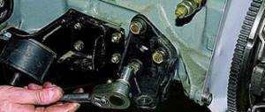
| 7. Unscrew the two nuts securing the intermediate arm bracket. |
NOTE
Please note: there are spring washers under the nuts. |
| 8. Remove the bracket from the studs. |
| 9. Disconnect the wires from the idle air control valve. |
| 10. Remove the pulley from the camshaft (see “Replacing the camshaft oil seal”). |
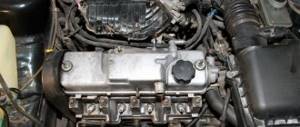
| 11. Remove the cylinder head cover (see “Cleaning the crankcase ventilation system”). |
| 12. Disconnect the hose from the spark torque sensor vacuum regulator. |
| 13. Unscrew the three nuts securing the spark torque sensor, remove it from the studs and move it to the side without disconnecting the block with wires from it. |
| 14. Unscrew the two nuts securing the fuel pump, remove the washers, remove the pump from the accessory drive housing studs and move it to the side without disconnecting the hoses from it. |
| 15. Remove the bolt securing the auxiliary drive housing. |
| 16. Remove the accessory drive housing from the studs. |
| 17. Unscrew the nut of the upper fastening of the rear cover of the camshaft drive belt. |
| 18. Remove the camshaft bearing housing (see “Replacing valve stem seals”). |
| 19. Take out the camshaft and remove the oil seal from it. | 20. Loosen the nut securing the generator to the tension bar. |
| 21. Unscrew the nut securing the tension bar to the cylinder block and remove the flat washer installed under it. |
| 22. Remove the eye from the hairpin... | 23. ... and the tension bar. |
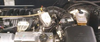
| 24. Remove the tension roller and spacer ring (see “Replacing the tension roller”). | 25. Loosen the clamps and disconnect the three hoses from the cooling jacket pipe. |
| 26. Slide the protective cap and disconnect the wire from the coolant temperature gauge sensor. | 27. Loosen the clamps and disconnect vacuum hose 1 (to the vacuum booster) and hose 2 for heating the intake pipe from the intake pipe fittings. |
| 28. Loosen the clamp and disconnect the fuel supply hose from the fuel pump to the carburetor. | 29. Unscrew the two nuts securing the exhaust pipe of the muffler on the left side of the head and... |
| 30. ...two nuts securing it on the right side of the head. | 31. Remove the six cylinder head bolts and remove the bolts and washers. |
| 32. Press the rear camshaft drive belt cover until the pin comes out of its hole. |
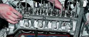
| 33. Remove the head from the cylinder block by removing the pins from the holes in the muffler exhaust pipe flanges. |
| 35. Clean the mating surfaces of the cylinder block and head. |
| 36. Remove oil from the threaded holes in the cylinder block for the head bolts. |
| 37. Blow out the jet in the oil channel of the cylinder block with compressed air and... | 38. ...block cylinders. |
| 39. Thoroughly wipe the cylinder mirrors and the mating surface of the cylinder block with a clean rag. |
| 40. Install a new gasket on the cylinder block. |
NOTE
The gasket must be clean and dry. |
| 41. Thoroughly wipe the mating surface of the block head with a clean rag. |
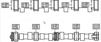
| 42. Install the head on the block, placing the exhaust pipe flanges of the muffler onto the head studs. | 43. Measure the length of the cylinder head bolts, as they stretch out with repeated use. Replace bolts longer than 135.5 mm with new ones. |
| 44. Lubricate the head bolts and washers with a thin layer of engine oil. |
| 45. Tighten the head bolts in the indicated sequence in four stages: |
| 1st - torque 20 N m (2 kgf m); |
| 2nd - torque 69.4–85.7 N m (7.1–8.7 kgf m); |
| 4th - finally turn it 90°. |
| 46. Thoroughly dry the camshaft with a clean cloth. |
| 47. Lubricate the camshaft journals and cams with a thin layer of engine oil. |
| 48. Install the camshaft into the cylinder head so that the valve drive cams of the first cylinder are directed upward from the valve tappets. | 49. Apply sealant to the surface of the block head in the areas where the bearing housing contacts. |
| 50. Install the camshaft bearing housing. |
| 51. Tighten the bearing housing nuts in the order shown in two stages: |
| 1st - tighten the nuts until the bearing housing touches the surface of the cylinder head; 2nd - finally tighten the nuts to a torque of 21.6 N m (2.2 kgf m). |
| 52. Press in the camshaft oil seal (see “Replacing the camshaft oil seal”). |
| 53. Install the parts on the head and connect hoses and wires to it in the reverse order of removal. |
| 54. Install the camshaft drive belt (see “Replacing the camshaft drive belt”). |
| 55. Check and, if necessary, adjust the clearances in the valve drive (see “Adjusting the clearances in the valve drive”). |
↓ Comments ↓
VAZ-1111-11113 OKA
Section 1. VEHICLE STRUCTURE
General information about cars Vehicle registration data
Section 2. ENGINE
Possible engine malfunctions, their causes and solutions Useful tips Replacing the coolant Replacing the engine oil and oil filter Cleaning the crankcase ventilation system Setting the piston of the first cylinder to the TDC position of the compression stroke Adjusting the tension of the camshaft drive belt Replacing the tension roller Replacing the camshaft drive belt Removing, installation and troubleshooting of the flywheel Replacement of engine seal parts Cylinder head Adjustment of clearances in the valve drive Removal and installation of the engine Engine repair Lubrication system Cooling system Exhaust system Power supply system
Section 3. TRANSMISSION
Clutch Gearbox Front wheel drives
Section 4. CHASSIS
Front suspension Rear suspension
Section 5. STEERING
Inspection and check of the steering system on the vehicle Steering column Steering mechanism Steering linkage
Section 6.BRAKE SYSTEM
Checking and adjusting the brake system Replacing the brake fluid Bleeding the brake system hydraulic drive Master cylinder Brake vacuum booster Pressure regulator Replacing brake hydraulic hoses and pipelines Front wheel brakes Rear wheel brakes Parking brake
Section 7. ELECTRICAL EQUIPMENT
Fuses and relays Generator Starter Ignition system Lighting, light and sound alarms Windshield wipers and washers Engine cooling fan Instrument cluster Switches and switches
Section 8.BODY
Possible body malfunctions, their causes and solutions Replacement of buffers Hood Side door Rear door Rear view mirrors Seats Heater Body care
Applications
Appendix 1. Tightening torques for threaded connections Appendix 2. Fuels and lubricants and operating fluids Appendix 3. Basic data for adjustments and control Appendix 4. Filling volumes, l Appendix 5. Oil seals Appendix 6. Layout of rolling bearings Appendix 7. Car electrical diagram : 1 — side turn signal repeater; 2 — front direction indicator; 3 - headlight; 4 — electric motor of the cooling system fan; 5 — sound signal; 6 - sensor for turning on the electric motor
Procedure
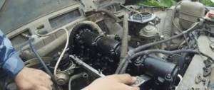
Having stocked up with everything you need, you can begin work.
The sequence of actions is as follows:
- We put the Oka in the garage or on a flat area, immobilize it, remove the terminal from the battery;
- We drain the coolant from the cooling system (place a container under the drain plugs, unscrew them and wait until the liquid drains. Replace the plugs and tighten them);
- Remove the air filter housing. Cover the carburetor neck with a rag. We disconnect the throttle and air damper cables from it, remove the gas drive mechanism with the lever and its mounting bracket, as well as the fuel pipes and the wire of the XX solenoid valve;
- Remove the protective cover of the timing drive. We install marks on the crankshaft and camshaft. shaft (this is especially important during partial disassembly);
- Loosen the tension roller so that it loosens the tension of the drive, and remove the belt from the camshaft wheel;
- Disconnect the fuel pipe from the fuel pump. Unscrew the pump fasteners and remove it;
- We disconnect the pipes from the valve cover, unscrew its fastening and remove it;
- We unscrew the nuts of the spark torque sensor, disconnect the wires from it, and move it to the side. We also remove the high voltage wires from the spark plugs;
- Unscrew the mounting bolt of the auxiliary units housing;
- We unscrew the fastening bolt of the camshaft gear and tighten it (carefully so as not to miss the key).
We also dismantle the tension roller;
- At the top, unscrew the fasteners of the rear timing drive cover and bend it to the side;
- We unscrew the nuts securing the exhaust pipes and pull them off the studs;
- We remove the pipe from the vacuum regulator;
- Unscrew the top bar used to tension the alternator belt;
- Disconnect the cooling system pipes coming to the head;
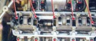
- Then it all depends on why the cylinder head is removed. If you only plan to replace the head gasket, then there is no need to dismantle anything further. We simply unscrew the cylinder head mounting bolts and remove it from the block along with the installed camshaft and intake manifold, change the gasket and put everything back together. In this case, after assembly work, valve adjustment will not be required, since the camshaft. the shaft was not removed. But if everything is dismantled for repairs, for example, it is planned to replace valves at Oka, then we do not unscrew the fastening bolts yet, but continue to disassemble further;
- Unscrew the camshaft bearing cover and remove it;
- We remove the camshaft;
- And only after that we unscrew the cylinder head mounting bolts, after which we dismantle it from the car;
And then repair work is already being carried out. But to do this, the intake manifold is first disconnected from the head. Then the pushers are removed along with the adjusting washers. Further, for disassembly, you will need a device for drying and drying the valves in order to remove them, after which repair work is carried out - replacing the valve guides, the valves themselves, grinding them in, etc.