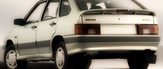
The search for possible reasons why the VAZ 2114 instrument panel may not work periodically worries one or another owner of cars of this model. It’s clear that if you don’t see a single parameter on the dashboard, you can only drive, as they say, by touch. True, there are certain specialists who still managed to somehow crawl to the base without all the evidence, but somehow I don’t want to follow their example.
And is it necessary to create possible troubles for yourself and increase the risk of getting into an accident? I think no! In today's article I want to tell you about the possible causes of a malfunction in the VAZ 2114 dashboard, and give some ways to repair it yourself.
VAZ 2114 – why doesn’t the dashboard work?
Why does the VAZ 2114 dashboard not work? There can actually be many reasons, here are some of them:
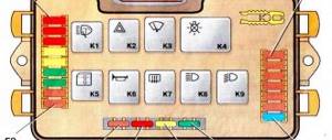
- Blown fuse
- Burnt tracks on the board cannot be repaired. In this situation, everything can be solved by installing a new circuit. You shouldn’t be afraid of this, its cost is not high, and you can replace it yourself.
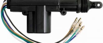
- A break in the electrical wiring can be called the most complex, unpleasant and difficult to identify type of breakdown. In this case, power is not supplied to the instrument panel or one of the indicators, and it stops working. The fault is determined using a multimeter. The required wire is called back, the location of the break or poor contact is determined and, if necessary, replaced or cleaned.
If the dashboard lighting suddenly goes out, check the lamp brightness adjustment knob. It is quite possible that the child who was sitting in your car before unscrewed it, setting it to minimum.
Warning icons on the panel
The steering wheel icon can light up in two colors. If the yellow steering wheel is on, then adaptation is required, and when a red image of the steering wheel with an exclamation mark appears, you should already be concerned about the failure of the power steering or power steering system. When the red steering wheel lights up, your steering wheel will probably become very difficult to turn.
The immobilizer icon usually blinks if the car is locked; in this case, the indicator of a red car with a white key signals the operation of the anti-theft system. But there are 3 main reasons if the immo light is constantly on: the immobilizer is not activated, if the tag on the key is not read or the anti-theft system is faulty.
The handbrake icon lights up not only when the handbrake lever is activated (raised), but also in cases where the brake pads are worn out or the brake fluid needs to be topped up/replaced. On a car with an electronic handbrake, the parking brake light may come on due to a glitch in the limit switch or sensor.
The coolant icon has several options and depending on which one is lit, draw conclusions about the problem accordingly. One red lamp with a thermometer scale indicates an increased temperature in the engine cooling system, but a yellow expansion tank with waves indicates a low coolant level in the system. But it is worth considering that the coolant lamp does not always light up at a low level; perhaps there is simply a glitch in the sensor or float in the expansion tank.
The washer icon indicates a low fluid level in the windshield washer reservoir. Such an indicator lights up not only when the level actually decreases, but also if the level sensor is clogged (the sensor contacts become coated due to poor-quality liquid), giving a false signal. On some vehicles, the level sensor is triggered when the washer fluid does not meet specifications.
The dashboard of the VAZ 2114 is out of order, what should I do?
If on a VAZ-2114 car on the instrument panel none of the indicators installed on it work (speedometer, odometer, tachometer, fuel level and coolant temperature indicators), then the first thing the driver will have to do is check the integrity of fuse F3, which is located in the mounting block. If it has burned out, then before replacing it, you need to find the reason why it burned out, otherwise the newly installed new fuse will have the same fate as the previous one. Most often, fuses burn as a result of a short circuit.
Even if the fuse is intact, then do not be lazy to take it out and check the condition of the contacts. There are cases when the contacts oxidize, and the electrical circuit in this place is interrupted. After making sure that the fuse is intact, the next step is to check the ignition relay, which is located inside the car to the left of the steering column. It is attached to a pin upside down. In the block where this relay is inserted, you can try to short-circuit the power wires using a jumper. If the instrument panel comes to life, the ignition relay will have to be replaced.
If the ignition relay is working properly, there are only two possible reasons for the instrument panel not working: the ignition switch and the mounting block. Before installing the ignition relay on the VAZ-2109 car, the lock contacts burned quite often, and they had to be cleaned by disconnecting the contact group from the lock itself. After changes were made to the principle of supplying voltage to the ignition switch, its contacts began to burn very rarely, but the likelihood of this phenomenon still remained. On the mounting block, in its board, tracks may burn out; in order to see this, the mounting block will have to be removed from the car.
In addition to the reasons listed above, which can lead to failure of the instrument panel, it is also necessary to check the reliability of fastening the ground wire.
Which wire goes where?
First, let's look at the back of the instrument panel. At the top there are:
- fuel level indicator;
- dashboard lighting lamps;
- control of right and left turns (separately);
- tachometer;
- block with many plugs;
- coolant temperature gauge.
As you can see, there is really nothing particularly complicated here. At the bottom of the instrument panel on the back side there are controllers:
- high beam;
- "emergency lights";
- CHECK ENGINE;
- battery charge;
- parking brake;
- oil pressure;
- air damper (for models with a carburetor);
- outdoor lighting work.
In addition, there is also a speedometer and a brake fluid level indicator lamp.
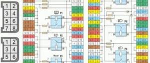
Now let's take a closer look at the pads. There are two of them - white and red. In the first, the connectors and wires look like this (in order):
- Ground wire black.
- Red-brown – low-voltage supply from the ECU to the tachometer.
- Yellow – high-voltage supply to the tachometer from the coil.
- Red-blue - comes from the battery through the 6th fuse Const with a voltage of 12 volts.
- Green-white - leads to the coolant temperature sensor.
- Green-yellow – fuse F1, responsible for the side lights.
- This connector has no color, it goes to the throttle valve.
- Red and white – leading to the CHECK ENGINE indicator light.
- 2 orange wires leading to two F19 + 12 volt power fuses.
- Same as the previous connector.
- 2 blue-brown wires leading to the “VK” terminal of the handbrake.
- The output to terminal D of the generator is a brown-white wire.
- Gray and blue - wire going to the oil pressure sensor.
In the red block, the connector number according to the account, the color of the wires and the devices to which they lead are as follows:
- Red-blue – leads to the external temperature sensor.
- Orange – goes to power fuse F19 + 12 volts.
- 2 black ground wires.
- White – leads to the instrument lighting switch.
- Blue – to the right turn indicator.
- Blue-black - to the left turn indicator.
- Blue-pink - to the brake fluid level sensor.
- Brown – leads to the on-board computer.
- Gray - to the speedometer.
- Pink – to the fuel level indicator.
- 2 green-black wires leading to fuse F3, which is responsible for the high beam.
- Blue-white - to the hazard warning switch.
- The white wire leads to terminal 50 - the ignition switch.
It is worth especially noting here that the most typical and common pinout diagram is shown above. However, different manufacturers may have differences in color markings. For example, in the instrument panel manufactured by the Kursk "Schetmash" there will be minor differences from the above diagram, in particular in the red block (connector number and wire color):
- black;
- red-brown;
- yellow;
- red and white;
- green-white;
- 2 brown wires;
- empty;
- red and white;
- blue;
- orange;
- blue-brown;
- white-brown;
- blue-gray.
As you can see, there are still certain differences, even if they are small. However, these little things are very important. Therefore, it is best, before starting work, to find out which panel your car has (by year of manufacture and manufacturer), and then find the correct pinout diagram. However, there is another option - the self-adhesive pieces of paper already mentioned above. When disconnecting the wires, be sure to label them - this will greatly facilitate the assembly process.
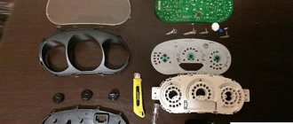
Instrument cluster VAZ 2110-11-12: All control devices of the car are combined into an instrument cluster. It includes: electronic speedometer and tachometer, coolant temperature indicator, fuel level indicator and 12 warning lamps. The instrument cluster is secured in the instrument panel socket with two screws. Instrument panel combinations are produced by the manufacturers Schetmash Kursk and VDO. In addition, on a VAZ 2110 you can install an instrument panel from a VAZ 2115 (with two windows), the instrument panel combination will display the correct information. In addition, there are combinations of instrument panels with a mechanical odometer.
Connection diagram of the instrument cluster VAZ 2110 2111 2112 (view from the back of the instrument cluster)
| Fig. 1 pinout of the VAZ 2110 instrument panel combination | |
| 1 – fuel reserve warning lamp; 2 – instrument cluster lighting lamps; 3 – right turn indicator lamp; 4 – left turn indicator lamp; 5 – plug block; 6 – coolant temperature indicator; 7 – indicator lamp for external lighting; 8 – control lamp for the carburetor air damper; 9 – oil pressure warning lamp; 10 – parking brake warning lamp; | 11 – battery charge indicator lamp; 12 – tachometer; 13 – control lamp “CHECK ENGINE”; 14 – speedometer; 15 – brake fluid level warning lamp; 16 – hazard warning lamp; 17 – control lamp for high beam headlights; 18 – fuel level indicator. Plugs 2, 3 , 8 , 9 in block X2 are speedometer pins 14 |
Instrument cluster.
All vehicle control devices are combined into an instrument cluster. It includes: electronic speedometer and tachometer, coolant temperature indicator, fuel level indicator and 12 warning lamps. The instrument cluster is secured in the instrument panel socket with two screws.
The connections of the instrument cluster are made by printed wiring on a board made of foil getinax. The board is attached to the back of the case. The connection diagram of the instrument cluster is shown in Fig. , the addresses of the plugs are in the table “Addresses of the output plugs of the instrument cluster”
The speedometer has two trip counters: one total, and the second “daily”. The daily counter can be set to zero using a button located on the instrument cluster itself. The daily meter can only be reset while the vehicle is stationary.
Some manufactured vehicles may have an electronic instrument cluster installed. It contains the same instruments and warning lights as the conventional instrument cluster. The instrument cluster can only be checked on a stand in a specialized workshop. The instrument cluster is beyond repair.
On-board control system display unit.
The unit contains an electronic control circuit with an audible alarm and 10 LED indicators: insufficient oil level, insufficient coolant level, insufficient washer fluid level, faulty exterior lighting lamps, unfastened seat belts, worn front brake pads and four open door indicators.
The addresses of the block plugs are given in the table “Addresses of the output plugs of the on-board monitoring system display unit.”
The order of the conditional numbering of the block plugs is similar to the numbering order of the plugs in the instrument cluster blocks (see Fig.
Connection diagram of the instrument cluster (view from the back side)
).
Addresses of the output plugs of the instrument cluster
| Plug | Pad address | |
| white (X1) | red (X2) | |
| Housing ("mass") | To terminal “W” of the fuel level indicator sensor | |
| Low voltage tachometer input | ||
| High voltage tachometer input | Housing ("mass") | |
| Spare | To the instrument lighting switch | |
| To coolant temperature sensor | To turn signal switch (starboard side) | |
| To fuse F1 of the mounting block | To turn signal switch (left side) | |
| To brake fluid level sensor | ||
| To the motor control controller | To the on-board computer | |
| To fuse F19 (“+” power supply) | To speed sensor | |
| To fuse F19 (“+” power supply) | To terminal “T” of the fuel level indicator sensor | |
| To the parking brake switch | To fuse F3 of the mounting block | |
| To terminal "D" of the generator | To hazard warning switch | |
| To oil pressure warning light sensor | To terminal “50” of the ignition switch | |
Addresses of the output plugs of the on-board control system display unit
| Plug | Address (purpose) of plugs |
| To fuse F19 (“+” power supply) | |
| Housing ("mass") | |
| To the lamp health monitoring relay | |
| To ignition switch microswitch | |
| To the lampshade | |
| To rear left door sensor | |
| To rear right door sensor | |
| To oil level sensor | |
| To coolant level sensor | |
| To washer fluid level sensor | |
| To the seat belt sensor | |
| To brake pad wear sensor | |
| To front left door sensor | |
| To front right door sensor |
* On right-hand drive vehicles, plug 2 is connected to ground.
Dashboard VAZ 2114 – autotest
Some VAZ cars have a “dashboard check” function, which allows the arrows to make a full turn from start to finish. Such an auto-test of the tidy when the ignition is turned on is available on some foreign cars (Nissan, Subaru). In this article we will tell you how to do an automatic test of the instrument panel on a VAZ. Let's start with the fact that it is not possible to implement the function of checking the tidy when you turn on the ignition on every model. If you turn on the ignition while holding the mileage reset button and the arrows describe an arc, then this panel will work. As a rule, such calibration of the instrument arrows is available on AutoPribor models with one window (single-line), but again not on all versions. To modify the instrument panel you will need:
- Electromagnetic relay, small-sized (12V). For example, Tianbo HJR 1-2C.
- Transistor KT 503. Can be replaced with almost any npn structure.
- Capacitor 100uF, electrolytic (16V).
- Resistors for 1koma, 6.8koma, 22koma.
The principle of operation of the circuit: the relay, with its normally closed contacts, closes the tidy button. When you turn on the ignition, the circuit starts working after half a second, and then turns on the relay, which opens the button.
This test of arrows and dashboard indicators is already available on all modern models. The only thing is that it acts differently on different samples. For example, there may be 1 pass of the arrows, or three, or until the button is pressed, or even a pass only up to half the scales. The speed of the instrument panel arrows also depends on the manufacturer and version of the device. In other words, an autotest is a test button that automatically activates when the device is turned on. If there is a test during the standard test, then there will be one during the autotest. Therefore, doing an auto test of the VAZ 2114 dashboard is not a problem.
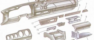
How to disassemble the dashboard of a VAZ 2114
Before embarking on this complex process, the driver must carefully familiarize himself with the design and arrangement of the instrument panel on his car. When disassembled down to the cogs, it looks like this:
If you carefully study this diagram, it becomes clear how to remove the panel on a VAZ 2114. Having determined the order for yourself, you can begin the process.
- Using a Phillips screwdriver, you need to unscrew the three screws holding the left console screen. For convenience, when doing this work, it is better to use a screwdriver with a short handle and blade.
- When removing the screen, carefully remove the lower edge of the trim from the body bracket.
- The right console screen is secured with five self-tapping screws. Using a Phillips screwdriver, carefully unscrew all the screws while holding the trim with your hand.
- Remove the screen without allowing it to get caught in the wiring harnesses that are hidden behind it.
- Disconnect the ground from the battery by disconnecting the connectors. If your car has a radio, disconnect it from the main bundle of wires by pulling out the connecting connector. If there is no radio installed on the car, then simply pull the wires out of the panel; they should be closed with a plug. Be sure to turn off the cigarette lighter and remove the socket with the ashtray light bulb.
- Remove the handles from the heater damper control levers. To make the process easier, pry them off with a flat-head screwdriver.
- Despite the apparent simplicity of this item, removing the handles from the levers can take a lot of time. To do this, a clear example is given of how this should be done on a removed unit.
- Remove the electric heater fan handle by simply pulling it towards you.
- Unscrew the cross-head screws securing the instrument panel to the brackets on the right and left with a screwdriver
- In the window on the instrument panel, where the instrument unit is located, there are two self-tapping screws at the top and two at the bottom - under the window. It is necessary to turn them out, loosening the cover (2) and the shield (8).
- Pull out the plug and unscrew the screw located behind it
- Remove the two screws from the bottom that hold the trim and remove it.
- Having marked the wires suitable for the switches, disconnect them.
- Remove the bolts from the steering wheel bracket
- Using the “8” key, unscrew the screws of the lower bracket fastening.
- Unscrew the self-tapping screw and remove the light guide.
- Remove the fasteners from the heating control unit and remove the cartridges from the back of the unit.
- remove the decorative insert, removing all external parts.
- Unscrew the nuts with a key set to “21”.
- Remove the hydraulic corrector illumination.
- Unscrew the upper and lower fastenings of the panel, and remove the fastening to the cross member on the left side.
- Now you can remove the VAZ 2114 torpedo.
- Installation is in the reverse order.
In order to clearly see the whole process in motion, you can watch a video on how to remove the dashboard on a VAZ 2114.
Euro torpedo VAZ 2114: advantages and disadvantages
The Europanel is perfect for installation on a VAZ 2114 and does not require additional alteration or adjustment.
Its quality significantly exceeds that of the panel provided by the factory, due to such points as:
- more modern design;
- better quality material (plastic);
- availability of built-in VDO devices (with internal lighting);
- presence of a digital odometer;
- original design of signal lamps;
- the presence of several additional compartments for storing small items;
- well-equipped air duct, etc.
In addition, the VAZ 2114 Europanel allows the driver, if necessary, to connect various additional sensors (for example, levels of antifreeze or windshield washer fluid or open doors).
Of course, the europanel has some disadvantages, including:
- not full amplitude (does not reach the edges of the slots) and tight movement of the air damper control levers;
- poor adjustment of rods and cables, etc.
Despite the existing shortcomings, installing a Europanel changes the appearance and comfort of the VAZ 2114 interior so much for the better that car drivers are increasingly resorting to this procedure.