Central locking diagram for VAZ 2114
To connect a car alarm to the central locking on a VAZ 2114, you need to know the circuit diagram of the central locking system itself. This will allow you to understand what should be connected to what. Below is a standard lock diagram.
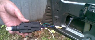
The control module is located under the vehicle's dashboard on the left side. There are six wires in its connector. If the white wire is connected to terminal 7, then it is responsible for unlocking the doors. But in some vehicles, terminals 5 and 7 may not be used. In this case, this function is performed by the brown wire connected to terminal 8. Terminals 5 and 6 are always responsible for locking. When planning to install the alarm, you need to make sure that the driver’s door contains exactly the 5-wire actuator, typical for this VAZ model. Some cars may have a toggle switch instead. In this case, you will need to install an actuator.
Central locking actuator
It is difficult to do this with your own hands without knowledge of auto electrics. Therefore, if they are absent, it is better to contact a car service.
Alarm connection points for VAZ 2114
Most modern alarms can be connected to the door, hood and trunk switches.
Therefore, in order to connect the signaling system to the VAZ 2114, you need to observe the following points:
- Connector X3 with a blue-red wire to the car door sensors;
- X9 – to a two-level shock sensor, which is attached to a metal surface;
- X8 and X7 – usually not used;
- X6 – to the Valet service button, which is placed in a place hidden from prying eyes in the car;
- X5 – LED alarm indicator, which is located on the dashboard;
- X4 – to the transmitting sensor receiving module. It is installed on the windshield in one of the upper corners;
- X3 – connector with a large number of wires.
To connect the car alarm to all car systems, you need to connect the wires in this order:
- Red – to the “plus” of the ignition switch;
- Black/green and green/yellow – to direction indicators and sidelights;
- Black – for vehicle weight;
- Yellow – to the ignition switch;
- Gray – positive emergency siren;
- Blue/red – “plus” door entrance;
- Black/red – additional blocking relay;
- Orange/gray – to the hood opening sensor;
- Orange/white – trunk opening sensor;
- Orange/purple – to the brakes, according to the diagram presented in the instructions for the security device. It may differ for signaling devices from different companies;
- X2 – to door opening activators;
- X1 – to the ignition switch. It should be connected to the red wire.
Connection diagram and setup
In the basic instructions, Starline provides a diagram for the A91 model:
Door limit switch cord
Shown here is the harness going to the dashboard. Let's figure out what is connected where:
- The diode connected to the wire break must conduct current in the direction “towards the limit switches”;
- Above we talked about the 1N5401 diode;
- The second diode connected to the alarm wire may be designated 1N4001 (it is cheaper).
The Starline A91 Dialog alarm is equipped with a set of inputs connected to the door, trunk and hood limit switches. The one you need is the "17" cord from connector X3. In the diagram it is designated as “blue-black”.
Now let's look at what is in the second bundle, located under the first:
Handbrake wiring harness
From the two blue cables shown above, make T-shaped bends and extend the cords to the alarm installation location. And a 1N4001 diode is installed in the gap in the handbrake wire. The cathode of this diode “looks” towards the switch. Finally you will make the connections:
- The “green-yellow” and “green-black” wires from connector X3 are connected to the turn signal leads.
- Another tap coming from the cathode is connected to the “brake input” of the Starline A91 Dialog signaling system. The cord is designated as “orange-purple”.
It was discussed how to connect all the signal wires with your own hands. Queue for the security forces.
The steps listed in this chapter can be completed before installing the alarm. The functionality of standard equipment should not be affected.
Connecting the autostart connector
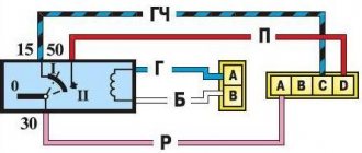
In VAZ 2114 cars, unlike the “nines”, an ignition switch with three terminals is used: 50, 15 and 30. The latter is connected to the battery, and contact 15 closes with it when the key is turned. Well, the 50th terminal is the “output "to the starter. Similar designations are used not only by VAZ.
As for model 2114, the lock escutcheon is secured with three self-tapping screws, as well as three metric screws. Unscrew them and you will see the following:
Car ignition switch connector
According to the basic instructions, power for the signaling can be taken from pin 30 (a T-tap is needed). And the “yellow” power cable coming out of connector X1 is connected to terminal 15. Further, if autostart is needed, then:
- The connections above must withstand significant current (up to 30 A);
- The “red” wire coming from the ignition switch is broken;
- The Starline A91 Dialog module is reached by bends coming from the break point;
- The thin wire from connector X1 should connect to terminal 50, while the power cord in “black and yellow” insulation will become the output to the starter.
Also, as stated in the installation manual, do not forget to cut the gearbox selector loop. The action makes sense if autorun is used.
The VAZ 2114 car is equipped with a manual transmission. You can set an alarm without performing the actions from the list. Otherwise, the loop must be opened. The point here is not only to follow the instructions, but also to be safe.
Those who have an immobilizer activated in their car will have to install a crawler. You can buy a BP-3 unit from Starline to connect it to the “pink” control cord of the alarm:
Including a lineman in a wiring break
All those who do not want to break the wire of the standard reader make a crawler with their own hands:
- The additional loop antenna contains 50 turns of PEL-0.3 wire;
- The internal antenna of the unit must contain the same number of turns of any wire;
- Both antennas are combined into a circuit opened by relay contacts.
The instructions cannot be completed here. The method of connecting the tachometer was not considered.
It is clear that the loop antenna will need to be combined with a standard reading device. And all the antennas included with Starline crawlers do not fit well with VAZ immobilizers.
The wire in “black-gray” insulation coming from connector X3 is connected to the high-voltage input of the tachometer (see figure). Your alarm will not burn out as a result, but will be able to control the speed:
Dashboard diagram 2114
All Starline security systems, as it turns out, are well compatible with any VAZ cars. This applies even more so to the A91 Dialog model. By the way, do not forget to connect the “ground” of the main unit (“black” cord of connector X3).
Software setup
We will configure only the functions responsible for autorun. You can activate the programming mode as follows:
- The security is turned off, the key in the lock is moved to the “0” mark;
- The Valet button connected to the A91 Dialog main unit is pressed 6 times;
- After step “3”, turn on the ignition immediately;
- 6 beeps sound;
- Use the Valet button to select the function number (see below);
- To set the required value, press the corresponding key on the key fob.
The system operates in Dialog mode, so the function number, as well as its value, will be displayed on the key fob. All the options in question are listed in the table:
Autorun options table
Information was taken from the installation instructions. Switch the values of the following functions: 12-3, 11-4 and 9-3.
To set the value to “4”, press the third key until the melody appears. Then the button is pressed again. Having chosen the value 4 for function 11, it is better to perform the following check:
- The “yellow” cord coming from block A91 and connected to terminal 15 is temporarily disconnected;
- Start the engine “with the key”;
- The alarm LED should start flashing.
All these tips are given in the standard instructions. True, they advise disconnecting all wires except three.
Screenshot of the basic guide
The A91 Dialog system can forcibly prohibit autostart. To prevent this from happening, you need to get out of the car correctly. First, activate the handbrake, then turn off the ignition (the engine is running). After leaving the car, you can activate the security mode. The motor stops.
Connecting to wires
Connection to the “four” wires must be carried out in the order indicated above. In this case, you must follow the instructions in the instructions for the alarm. But first you need to place all the alarm elements in the car. Before starting work, turn off the battery power. The device control unit is placed under the dashboard. The siren must be located in the engine compartment. An emergency siren should also be installed there. In the trunk, under the hood, and also in the engine compartment, you need to install limit switches for opening. Place the Valet button in a place hidden from prying eyes. Attach the antenna of the security device to the windshield in the upper right or left corner. Place the shock sensor on a metal surface. Next, the car alarm is connected according to the diagram. To connect it to the central locking you need to purchase the following items:
- 2-3 pieces of 1N4001 diodes for a current of no more than one Ampere;
- One 1N5401 3 Ampere diode;
- Also, some security systems may require two 4-5 Ampere power diodes.
To connect the device to the central locking system, you need to find two wire harnesses on the floor next to the driver's door. To get them, you need to remove the sill trim and side panel. The first harness contains the door switch cable. A 1N5401 diode must be installed in its gap.
In the second harness you need to find the wire going to the handbrake, into which you should insert the second 1N4001 diode.
The blue cords of both harnesses must be connected to the car alarm.
Car alarm system Tomahawk 9010
The anti-theft system kit consists of:
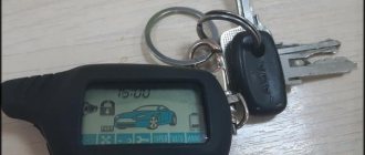
- remote control with liquid crystal display;
- one-sided keychain;
- shock sensor;
- one relay;
- receiving and transmitting module;
- Anti-Hi-Jack buttons;
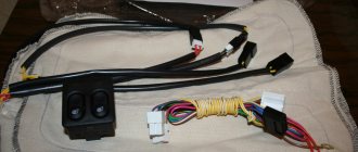
- mode switching keys;
- LED indicator;
- ten wires;
- one limit switch;
- car stickers;
- installation tools;
- temperature sensor;
- instructions for installing a car alarm;
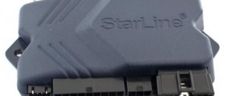
- central control unit.
An important component of the kit is the connection manual, without which it is impossible to correctly connect and configure the anti-theft system.
Connecting autorun
If the alarm has an autostart function, it can be implemented on the “fourteenth”. The ignition switch of this car is equipped with three terminals:
- 15 – blue wire;
- 30 – lilac cable;
- 50 – red wire.
To connect the alarm you will need a 30 connector. The cable coming from terminal X1 should be connected to pin 15. The gray-black wire from connector X3 must be connected to the tachometer. This way the alarm will be able to read the revolutions. The black cable of terminal X1 is connected to ground. The red wire from the ignition switch needs to be broken. You should also cut the loop responsible for selecting the transmission, since the car is equipped with a manual transmission.
After the work has been done, you should configure the autostart according to the instructions for the car alarm.