The braking system (TS) of any vehicle is designed to control the speed of movement, stop and hold it stationary for the required period of time.
It is one of the most important vehicle control systems, since road safety functionally depends on the degree of serviceability and efficiency of the braking system.
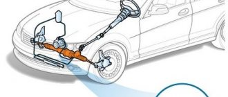
Brake system diagram: 1 - brake disc; 2 — brake pedal; 3 - vacuum booster; 4 — master cylinder for hydraulic brakes; 5 — pipeline of the front brake drive circuit; 6 — front brake protective cover; 7 — front brake caliper; 8 - vacuum pipeline; 9 — master cylinder reservoir; 10 — parking brake lever button; 11 — parking brake drive lever; 12 — lever latch rod; 13 — lever latch; 14 — bracket for the parking brake drive lever; 15 — return lever; 16 — pipeline of the rear brake drive circuit; 17 — flange of the cable sheath tip; 18 — rear brake wheel cylinder; 19 — rear brake pressure regulator; 20 — pressure regulator drive lever; 21 — brake pads; 22 — lever for manual drive of the pads; 23 — rod of the pressure regulator drive lever; 24 — bracket for fastening the tip of the cable sheath; 25 — rear cable; 26 - lock nut; 27 — adjusting nut; 28 - bushing; 29 — rear cable guide; 30 — guide roller; 31 — front cable; 32 — parking brake warning lamp switch stop; 33 - brake light switch
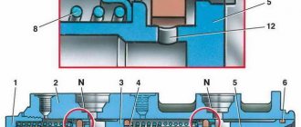
Diagram of the brake system: rear brakes VAZ 2107: 1. Springs of pins securing the pads; 2. Cotter pin; 3. Pad pressure spring; 4. Brake pads; 5. Brake caliper; 6. Brake disc; 7. Protective cover; 8. Brake pad mounting pin; 9. Fitting for bleeding the brake drive; 10. Cylinder connecting tube; 11. Piston; 12. Wheel cylinder; 13. Piston O-ring; 14. Friction lining of the pad; 15. Piston protective cap; 16. Cylinder lock; 17. Rivet securing the support and guide plates of the pads; 18. Lower tension spring of pads; 19. Guide plate; 20. Brake pad; 21. Rear parking brake cable; 22. Rear cable spring; 23. Rear cable end; 24. Parking brake lever; 25. Brake pad spacer; 26. Pad drive lever pin; 27. Wheel cylinder housing; 28. Piston spacer spring; 29. Fitting for bleeding the rear brake drive; 30. Brake fluid supply tube fitting; 31. Piston sealing ring; 32. Cylinder piston; 33. Wheel cylinder protective cap; 34. Pad stop; 35. Upper tension spring of pads; 36. Friction lining of the pad; 37. Pad edge; 38. Spring; 39. Axis; 40. Spring bushing; 41. Friction washers; 42. Automatic device axle bushing; 43. Cable sheath; 44. Guide spring; 45. Brake mechanism support shield; 46. Pad support plate I. Front wheel brake mechanism; II. Rear wheel brake mechanism.
Diagram of the brake system: front brakes VAZ 2107: Brake mechanism of the front wheel: 1 - fitting for bleeding the front brake drive; 2 — connecting tube of working cylinders; 3 — brake pad wear indicator wire; 4 — wheel cylinder piston; 5 — wheel cylinder clamp; 6 — brake pad lining; 7 - sealing ring; 8 — dust cap; 9 — pins for securing the pads; 10 — bolt securing the caliper to the bracket; 11 — steering knuckle; 12 — caliper mounting bracket; 13 — caliper; 14 — protective casing; 15 — cotter pin; 16 — pad pressure spring; 17 — brake pads; 18 — wheel cylinder; 19 — brake disc
Braking system of modern cars
The general braking scheme on modern cars suggests the presence of three main types:
- working;
- spare;
- parking
The working vehicle performs the functions of reducing the speed of the vehicle or stopping it.
The spare vehicle is intended to prevent malfunction or failure of the working system.
The parking vehicle performs the functions of holding the vehicle stationary in special conditions and in parking mode. The VAZ-2107 implements a working and parking vehicle in a “pure” form.
In a modern car, braking can be performed not only by the vehicle itself, but also by the engine, electric or hydraulic transmission brake. In addition, additional systems (or devices) are often implemented that increase the productivity of braking functions:
- anti-lock braking system (the notorious ABS);
- electric brake force distribution (or EBD);
- electrical stabilization system (ESP), etc.
The described devices and systems lead to a significant increase in the cost of the vehicle, and the VAZ-2107 brake system diagram does not provide for them.
However, domestic cars have recently begun to provide similar capabilities.
General structure of the working vehicle
The schematic diagram of the vehicle includes the following elements:
- brake mechanism;
- brake drive.
The brake mechanism implements the function of braking - achieving the torque that is necessary to reduce the speed of movement or stop.
The VAZ-2107 is equipped with a classic version of friction mechanisms based on friction force.
Their design can be represented by the following two options:
- disk (compression mechanism);
- drum (unclamping mechanism).
In the VAZ-2107, a disc mechanism is used on the front wheels, and a drum mechanism on the rear.
A brake actuator is needed to control the braking mechanisms. There are mechanical, pneumatic, hydraulic, electric and combined operating principles of drives. The VAZ-2107 uses the most common hydraulic principle, based on the action of brake fluid (a special oily substance).
The hydraulic drive circuit includes:
- brake pedal (to control the hydraulic drive);
- vacuum booster (to create additional force when pressing the pedal);
- master brake cylinder with an expansion tank (to ensure an increase or decrease in fluid pressure in the dual-circuit system, as well as to replenish fluid);
- wheel (or working) cylinders (to bring the control functions of the pedal to the brake mechanism);
- rear brake pressure regulator (to adjust the braking force as the vehicle weight increases);
- pipelines and hoses (for placing and moving brake fluid throughout the system).
The implementation of braking functions in the VAZ-2107 (as well as in related models - sedans 2101, 2103, 2105, 2106 and station wagons 2102, 2104) involves the use of two parallel independent hydraulic drive circuits. In the event of a malfunction of one circuit, the braking functions are redistributed to the second.
General structure of the braking system
The schematic diagram of the vehicle includes the following elements:
- brake mechanism;
- brake drive.
The brake mechanism implements the function of braking - achieving the torque that is necessary to reduce the speed of movement or stop.
The VAZ-2107 is equipped with a classic version of friction mechanisms based on friction force.
Their design can be represented by the following two options:
- disc (compression mechanism) front brakes;
- drum (unclosing mechanism) rear brakes.
A brake actuator is needed to control the braking mechanisms. There are mechanical, pneumatic, hydraulic, electric and combined operating principles of drives. The VAZ-2107 uses the most common hydraulic principle, based on the action of brake fluid (a special oily substance).
The hydraulic drive circuit includes:
- brake pedal (to control the hydraulic drive);
- vacuum booster (to create additional force when pressing the pedal);
- master brake cylinder with an expansion tank (to ensure an increase or decrease in fluid pressure in the dual-circuit system, as well as to replenish fluid);
- wheel (or working) cylinders (to bring the control functions of the pedal to the brake mechanism);
- rear brake pressure regulator (to adjust the braking force as the vehicle weight increases);
- pipelines and hoses (for placing and moving brake fluid throughout the system).
The implementation of braking functions in the VAZ-2107 (as well as in related models - sedans 2101, 2103, 2105, 2106 and station wagons 2102, 2104) involves the use of two parallel independent hydraulic drive circuits. In the event of a malfunction of one circuit, the braking functions are redistributed to the second.
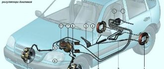
The device of the brake system of the VAZ 2107
RTS structurally consists of:
- Brake master cylinder (MBC) (item 4).
- Vacuum brake booster (VUT) (item 3).
- Brake pedal assembly (item 24).
- Containers for brake fluid equipped with a level sensor (item 8).
- Brake mechanisms (disc type) of the front wheel pair (items 1, 2, 6).
- Braking mechanisms (drum type) of the rear wheel pair (pos. 15, 16).
- Brake fluid pressure regulator in the rear brake circuit (item 12).
- Brake line pipelines (items 5, 7, 11).
STS structurally consists of:
- Adjustment unit (pos. 18, 20)
- Parking brake lever (item 10).
- A cable system, including front (pos. 21) and rear (pos. 17) cables.
- The lever for actuating the brake pads (item 14).
- Guide (pos. 19).
- The drive of the STS “seven” is mechanical, cable type.
How does a hydraulic braking system work?
The functioning diagram of the VAZ-2107 brake system is typical. Pressing the brake pedal (through the vacuum booster) moves the piston in the master cylinder, which creates fluid pressure and forces it to move through the pipelines to the wheel brake mechanisms.
Under the influence of fluid pressure, the cylinder pistons help move the brake pads of the front wheels to the discs, and the rear wheels to the drums. The result of the movement of the pads is their contact with the discs and drums and the slowing down of the latter. The friction force of the braking wheels with the surface of the roadway leads to a general slowdown of the vehicle.
The braking stop circuit involves releasing pressure on the brake pedal and moving the fluid back to the master cylinder. This means a drop in fluid pressure in the system and loss of contact between the pads and drums and discs, that is, the cessation of braking.
The same principle underlies the braking process on “classic VAZ models (from 2002 to 2106). The only exception that the VAZ-2101 system circuit has is the absence of a vacuum booster.
The principle of operation of the brake system in a VAZ-2107 car
When a driver wants to slow down his car, he presses the brake pedal. At this moment, its force is transmitted to a valve in the hydraulic booster, which opens a channel for supplying atmospheric pressure to one of the chambers. In this case, the emerging pressure begins to put pressure on the membrane, which is connected to a rod connected to the piston of the master brake cylinder. As a result, under the pressure of the membrane, the cylinder rod begins to squeeze brake fluid into the pipelines that lead directly to the wheel brake mechanisms. Since the fluid is not compressed at all, all the force is transferred directly to the brake mechanisms. The fluid presses on the internal pistons of the working brake cylinders, they extend and act on the brake pads (in brake drums the pads are unclenched, and in disc mechanisms they are pressed directly against the discs). Due to the friction of the brake pads on the drums and discs, the rotation of the car's wheels slows down.
Ineffective braking system
The most common malfunction of the brake system (including the VAZ-2107) is inefficiency, which is diagnosed by two main parameters (when carrying out a specialized instrumental study):
- increasing braking distance;
- increase in steady deceleration during braking.
Such faults can be determined by eye. After driving a passenger car on a dry road at a speed of 40 km/h, when braking, the car travels a distance exceeding 12.2 m. In this case, according to paragraph 2.3.1 of the traffic rules, the use of the vehicle is prohibited (even to the parking or repair site) .
This malfunction may be due to:
- presence of air in the system;
- fluid leakage from the system;
- worn out pads;
- failure of the main or wheel cylinders.
In other words, almost the entire vehicle should be subject to monitoring. Repair (replacement) of components and assemblies will require bleeding the system to remove air from it.
Parking brake malfunction
This defect is the most common when the car moves involuntarily even with the handbrake locked. This is due to wear on the pads, discs or drums, as well as stretching of the cable elements.
According to the requirements of the “List...”, a parked vehicle must ensure that the passenger car is stationary:
- on a slope of up to 16% at full load;
- on a 23% slope when equipped.
In the event that these requirements are not met, the vehicle can only be driven to a parking or repair site. Repair of the malfunction is ensured by adjusting the cable tension with a special nut or replacing worn parts.
Relative faults
This list of faults does not apply to absolute (or categorical) faults. Their presence is associated with the convenience (or inconvenience) of driving.
Increased brake pedal travel
The reasons for the “sinking” of the pedal are determined by the presence of air in the system; extreme wear of brake pads; failure of the main or wheel cylinders. The action plan for eliminating technical problems includes checking and repairing all components and assemblies of the system; and, if necessary, replacing failed ones and bleeding the system.
Car shifts to the side when braking
The malfunction is due to either a failure of the working (wheel) cylinder or wear of the pads. Replacing them (or repairing them) will solve the problem.
Grinding, friction
Deficiencies are localized mainly in the rear mechanisms and are determined by contamination of the mechanism, critical wear of the pads, breakage of spring elements, uneven wear of discs or drums. Fault repair involves washing and replacing mechanism parts.
Vibration during braking, beating in the steering wheel
This is a fairly common malfunction that is associated solely with critical or uneven wear of the discs or drums, and the repair will consist of replacing them.
Relative vehicle malfunctions
This list of faults does not apply to absolute (or categorical) faults. Their presence is associated with the convenience (or inconvenience) of driving.
Increased hydraulic pedal travel (as an option - a “soft” pedal)
The reasons for the “sinking” of the pedal are determined by the presence of air in the system; extreme wear of brake pads; failure of the main or wheel cylinders. The action plan for eliminating technical problems includes checking and repairing all components and assemblies of the system; and, if necessary, replacing failed ones and bleeding the system.
Shift towards the vehicle's trajectory when braking
The malfunction is due to either a failure of the working (wheel) cylinder or wear of the pads. Replacing them (or repairing them) will solve the problem.
Increased background noise, friction (grinding) in the brake mechanism
Deficiencies are localized mainly in the rear mechanisms and are determined by contamination of the mechanism, critical wear of the pads, breakage of spring elements, uneven wear of discs or drums. Fault repair involves washing and replacing mechanism parts.
Vibration when braking
This is a fairly common malfunction that is associated solely with critical or uneven wear of the discs or drums, and the repair will consist of replacing them. » alt=»»>