November 27, 2015 Lada.Online 237 045 150
The solution to any problem related to the electrical equipment of a car begins with checking the fuses. They, together with the relay, are located in the mounting blocks (fuse box and black box) of the passenger compartment or engine compartment.
The lists contain a complete set of fuses and relays, taking into account all vehicle configurations. In simpler versions, individual relays and fuses from this set may not be used.
Power unit in the engine compartment
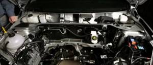
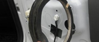
The mounting block itself is located near the battery (shown in the photo below). All electrical circuits in it are reliably protected from moisture and dust using a sealed cover equipped with special latches. This adds a little comfort when operating the car.
To open the specified cover, you need to press the two latches along the edges, which are shown by arrows in the photo below.
After the block is opened, many fuses and executive relays are revealed. To avoid confusion, we numbered them all in the photo below and added a description to each element in Table 1.
The circuits that the fuses protect are shown in Table 1.
Table 1. Circuits protected by fuses in the engine compartment block
In some car modifications, the horn is protected by fuse F78 instead of F73. And food is extra. equipment in the trunk is protected by fuse F55.
The relays that are located in this block are also summarized in Table 2:
Table 2. Relays located in the engine compartment block.
Components for Lada Vesta
Replacement of fluorescent type fuses must be carried out with those elements, the types of which are allowed for Lada Vesta. They are produced by manufacturers who have the appropriate conclusion from AvtoVAZ, with the markings indicated in Tables I, II and III.
Location of fuses and relays in the mounting block of the Lada Vesta interior.
Table I
This table provides a breakdown of electrical circuits that are protected by installing fusible elements. These fuses are located in the mounting block. The table shows all types of relays and fuses that are used in Lada Vesta. Therefore, it is worth remembering that some of the components may not be available in certain configurations.
Table II
Table II shows those relays that are located in the mounting block. It presents all types of relays that are used in Lada Vesta. Therefore, it is worth remembering that some of the components may not be available in certain configurations.
Table III
This table shows all the electrical circuits that are protected by fuses that are located in the block directly under the hood. The table shows all types of electrical circuits that are available in Lada Vesta. Therefore, it is worth remembering that some of the components may not be available in certain configurations.
Table IV
In the indicated table, the relays that are located in the mounting block of the engine compartment are repaired. The table shows all types of relays that are used in Lada Vesta. Therefore, it is worth remembering that some of the components may not be available in certain configurations.
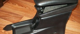
Block in the car interior
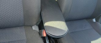
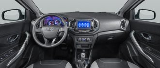
The passenger compartment fuse box is located below the left of the steering column.
Opening the lid on the old version before modification
To gain access to it, you need to remove the special clamps (before modification) that hold the cover diagonally from the bottom, and then pull it from the bottom. Don't forget about the upholstery holder lock. It must be carefully disconnected. In addition, in order for the cover to be removed completely, you will need to disconnect two connectors from the luggage compartment button and the electric headlight adjustment.
There is also a modified version of the cover. How to remove it - watch the video:
After removing the cover, you will see a mounting block with all low-current fuses and relays.
The main fuses are located in 2 rows. The counting goes from below from F1-F20 and from F21-F40 in the second row, respectively.
Slightly higher are the more powerful (20A-30A) F41-F46. The relays run along the left side of the block, also starting from the bottom.
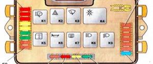
Rice. 2. Schematic location of relays and fuses
In new modifications, the fuse box has been supplemented with:
Here is a list of all circuits with the numbers of the fuses by which they are protected. To check whether the fuse is working, it is enough to shine it into the light and a break in the fusible metal inside will be visible if it is faulty.
Attention! Before installing a new replacement fuse, make sure that the circuit being protected is actually working and there is no short circuit. After all, fuses don't just blow! This means there was some kind of overload, from which the fusible element saved the wiring and the car from fire.
Table 3. Description of fuses in the interior block (until 2020).
| Fuse no. | Rated current | Protected vehicle circuit |
| F1 | 15A | Right steering column switch power supply, windshield washer |
| F2 | 30A/5A | Left steering column switch |
| F3 | 10A | Left high beam headlight, non-luxury equipment |
| F4 | 30A/5A | Left steering column switch |
| F5 | 15A | Seat heating |
| F6 | 7.5A | Right side lights |
| F7 | 10A | Left side lights |
| F8 | 5A | Rear fog lights |
| F9 | BEHIND | Right turn signal in the mirror |
| F10 | 5A | AMT robotic gearbox selector |
| F11 | 10A | Left low beam headlight (not luxury) |
| F12 | 15A | BCM Controller (Turn Signals) |
| F13 | 10A | BCM controller (self-powered) |
| F14 | 10A | Turning off the brake pedal |
| F15 | 5A | Power supply for rain and light sensor, headlight range control |
| F16 | 5A | Turning off the brake pedal |
| F17 | 5A | Lighting for trunk, glove compartment, sills |
| F18 | 3A | Left turn signal in the mirror |
| F19 | 10A | Right low beam headlight (not luxury) |
| F20 | 5A | Heated exterior mirrors |
| F21 | 15A | BU SNPB |
| F22 | 5A | Instrument cluster |
| F23 | 5A | Instrument cluster |
| F24 | 5A | ERA GLONASS, radio |
| F25 | 5A | ESP9.1 controller |
| F26 | 15A | Power supply to fuel pump module |
| F27 | 5A | Power supply for parking sensors |
| F28 | 5A | EURU controller (electric power steering) |
| F29 | 10A | Power supply for trailer lighting |
| F30 | 5A | ERA GLONASS controller |
| F31 | 5A | ERA GLONASS controller |
| F32 | 10A | K15M Bus Power (Engine Compartment) |
| F33 | 5A | Window control |
| F34 | 5A | Power supply for steering angle sensor, steering wheel button block |
| F35 | 5A | Driver's door switch block |
| F36 | 15A | Radio, diagnostic connector |
| F37 | 7.5A | Stop lamps, right |
| F38 | 7.5A | Stop lamps left |
| F39 | 10A | DRL (not luxury) |
| F40 | 10A | Right high beam headlight not luxury equipment |
| F41 | 20A | 12V socket (power supply for additional devices), cigarette lighter fuse for Lada Vesta |
| F42 | 20A | BCM controller (VTR bus power supply) |
| F43 | 20A | BCM Controller (Door Locks) |
| F44 | 30A | Window lifters |
| F45 | 30A | Interior heater fan |
| F46 | 30A | Wiper (switch power) |
| F47 | 25A | EMM controller (PDS, lBS, lGO) |
| F48 | 30A | EMM controller (windshield wiper) |
| F49 | 25A | EMM controller (PTF, ZPTO, license plate lighting) |
| F50 | 25A | EMM controller (lDS, PBS, PGO) |
Fuse table from February 2020:
All that remains is to figure out the relays used and the circuits that they switch in the block. The description is given in the table below.
Table 4. Description of the relays located in the interior unit.
| Relay | Relay rating | Switched circuit |
| K1 | 70/50A | Power supply for lighting and seat heating |
| K2 | 30A | Reserve |
| K3 | 30A | Heated rear window |
| K4 | 30A | Front windows |
| K5 | 40A | Interior heater fan |
| K6 | 30A | Rear window lifter |
| K7 | 20A | Fuel pump module |
| K8 | 20A | ACC accessories (+12V socket power supply) |
Description of fuses on a Lada Vesta car: location, diagram, price
Lada Vesta cars are equipped with knife-type modules in the following modifications:
- Mini;
- JCase
The manufacturer abandoned the installation of cylindrical modules 7 years ago due to the obsolescence of the model.
Relay-breaker layout diagram
| Designations | Who is responsible for what/what provides |
| K 1 | Lighting, seat heating |
| K2 | Responsible for the cigarette lighter |
| K 3 | Heated rear window |
| K 4 | Front windows |
| K5 | Interior heater (stove) |
| K 6 | Window lifter for rear doors |
| K 7 | Gasoline pump |
| K 8 | Car socket (powered by 12 Volts) |
| K9 | Heated windshield |
| K 10 | Heating relay |
| K11 | Starter |
| K 12 | Sound signal |
| K 13 | Beep (optional) |
| K 14 | Relay KSUD |
| K 15 | Air conditioning system |
| K 16 | Compressor clutch |
| K 17 | Cooling fan |
Lada Vesta fuse installation diagram
| Marking/amperage | What he is responsible for (with description) |
| F (F-1) / 20 | Windshield washer |
| F (F-2) / 5 | Understeering's shifter |
| F (F-3) / 10 | High beam (left headlight) |
| F (F-4) / 10 | Steering column switch (left) |
| F (F-5) / 20 | Heated seats |
| F (F-6) / 30 | Side lights (right) |
| F (F-7) / 30 | Left dimensions |
| F (F-8) / 7.5 | Rear fog lights |
| F (F-9) / 10 | Right turn signal repeaters |
| F (F-10) / 10 | Automated gearbox selector |
| F (F-11) / 10 | Low beam (left side) |
| F (F-12) / 10 | Direction indicators |
| F (F-13) / 30 | Power circuit |
| F (F-14) / 30 | Stop signals |
| F (F-15) / 10 | Rain sensor, external lighting, hydraulic headlight range control |
| F (F-16) / 15 | Stop light (optional) |
| F (F-17) / 15 | Illumination of the glove box, thresholds |
| F (F-18) / 10 | Turn signal repeaters (left) |
| F (F-19) / 10 | Low beam (right) |
| F (F-20) / 10 | Heated mirrors (external) |
| F (F-21) / 5 | Instrument panel (panel) |
| F (F-22) / 5 | —/— |
| F (F-23) / 5 | —/— |
| F (F-24) / 5 | ERA GLONASS |
| F (F-25) / 5 | ES9.1 controller |
| F (F-26) / 5 | Gasoline pump |
| F (F-27) / 20 | Parktronic |
| F (F-28) / 15 | Electric power steering |
| F (F-29) / 15 | Line output to tow hitch |
| F (F-30) / 20 | ERA GLONASS (optional) |
| F (F-31) / 15 | ERA GLONASS (optional) |
| F (F-32) / 15 | Engine compartment lighting |
| F (F-33) / 5 | Window lifters |
| F (F-34) / 15 | Steering wheel rotation sensor |
| F (F-35) / 5 | Door program block |
| F (F-36) / 15 | Radio, diagnostic connector |
| F (F-37) / 15 | Stop light (optional) |
| F (F-38) / 15 | Stop light (optional) |
| F (F-39) / 15 | Daytime Running Lights |
| F (F-40) / 20 | High beam (right) |
| F (F-41) / 20 | Standard cigarette lighter |
| F (F-42) / 20 | Bus power |
| F (F-43) / 20 | Door locks |
| F (F-44) / 20 | Window lifters |
| F (F-45) / 20 | Heater fan (interior) |
| F (F-46) / 20 | Windshield wiper (windshield wipers) |
| F (F-47) / 15 | PDS, LBS, LGO |
| F (F-48) / 15 | Windshield wiper (optional) |
| F (F-49) / 15 | PTF, ZPTO, license plate |
| F (F-50) / 15 | PDS, LBS, LGO (optional) |
| F (F-51) / 70 | Electric power steering |
| F (F-52) / 30 | Heated rear window |
| F (F-53) / 40 | Stability Program (ESP) |
| F (F-54) / 15 | Air conditioning system |
| F (F-55) / 5 | Reservation |
| F (F-56) / 15 | Automatic transmission |
| F (F-57) / 15 | Reservation |
| F (F-58) / 70 | Transmission optional |
| F (F-59) / 15 | Air conditioner |
| F (F-60) / 15 | Fuse supply circuit |
| F (F-61) / 60 | Generator |
| F (F-62) / 10 | Beep (optional) |
| F (F-63) / 5 | Reversing light |
| F (F-64) / 15 | Anti-theft alarm |
| F (F-65) / 15 | central locking |
| F (F-66) / 20 | Canister, air flow sensor, timing valve |
| F (F-67) / 15 | Fuel pump, charging |
| F (F-68) / 15 | Reservation |
Causes of fuse failure
- Failure to comply with the scheduled technical inspection schedule;
- Installation of non-original spare parts;
- Unprofessional installation;
- Mechanical damage to adjacent mechanisms and units;
- Short circuit in the wiring;
- Damage to the insulating layer;
- Oxidation of contacts;
- Loose fixation of terminal blocks;
- Condensation formation, moisture penetration into the structure.
Graphic cheat sheet
To make it easier for you to find a faulty fuse, we have prepared a graphical hint for you with markings and numbering of elements.
Fuses with reference to external and internal equipment for 2020.
Fuses linked to external and internal equipment from 2020 onwards.
If you still have questions on the topic, we will be glad to see them in the comments to this post.
Replacing fuses on Lada Vesta
- We place the Lada Vesta on the platform, block the rear row of wheels with wheel chocks, open the driver's door;
- To the left of the steering column, at the bottom, unsnap three plastic latches;
- Remove the cover under which the mounting block is located;
- Using plastic tweezers, remove the modules one by one and check the integrity of the melting plate. This method is applicable only when we do not know exactly the serial number of the faulty fuse.
To speed up the process of identifying a faulty element, serial numbers, module markings, and also pinouts are indicated on the back of the cover.
We replace fuses in the engine compartment by analogy:
- To disassemble the power supply housing: open the hood; on the left side, behind the battery, there is a mounting block;
- We unclip the plastic cover, remove the faulty module with tweezers, and insert a new one;
- We check the relay - switch for serviceability. We install a new one as needed.
The average service life of domestically produced fuses is 45 thousand km. Foreign analogues last longer by 10 - 15 thousand km.
If difficulties arise with installing the mounting block or replacing fuses, contact a service station specialist.