April 16, 2020 Lada.Online 25 290 8
We previously wrote that since July 2020, AvtoVAZ has changed the supplier of air filters for the Lada Vesta engine. However, this was not limited to replacing the filter. Along with another filter for the Lada Vesta family of cars, the plant began installing a new engine intake system. There are no official statements about the purpose for which this was done. Car enthusiasts tried to figure out the reason for the design change on their own.
Standard manifold (receiver) – article number and price
The intake manifold of the Lada Vesta, which is called the “intake module,” is known under catalog number 21177-1008-600-00. It is sold assembled, its average market price is from 4,000 to 5,000 rubles.
The release module is not sold assembled; you will have to assemble it yourself from:
exhaust pipe assembly (article 21129-1203008-01, 21129-1203008-00, cost from 20,000 rubles), exhaust manifold gaskets (21124-1008089-00, cost 400-500 rubles), M8x35 studs (catalog number 00001- 003543721), flat washers 8x17 (catalog number 00001-000519601), nuts M8x1.25 (catalog number 00001-006100811).
Main receiver malfunctions on Lada Vesta
Many owners of Lada Vesta CNG report a malfunction of the intake module. This applies to Vest with gas equipment running on methane. It was discovered that there is no through hole in the vacuum sampling fitting in the intake module. Owners are invited to visit an authorized dealer to have this fault checked, repaired and documented. After the visit, as CNG owners note, the acceleration dynamics increased, and at idle the speed stopped “jumping”.
Owners of Lada Vesta without LPG complained about the hose for the pneumatic drive of the intake manifold flaps. It quickly cracks, and when replaced, they install exactly the same one. The problem is solved by installing hoses for the classic Zhiguli instead of the original hoses on the Vesta.
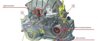
The exhaust manifold, filling with exhaust gases, constantly heats up. This makes it difficult to locate the engine and intake system next to the exhaust module. The catalyst involved in cleaning “suffers” very much not only due to constant heating, but also due to engine operating errors and “contaminants” in the fuel that “feeds” the car.
Control systems SU 21129 Lada Vesta
Engine ignition system 21129
The ignition system of the 21129 engine uses 4 individual ignition coils (Fig. 1).
The ignition system has no moving parts and therefore requires no maintenance or adjustment, with the exception of the spark plugs.
The current in the primary windings of the ignition coils is controlled by a controller that uses information about the engine operating mode received from the sensors of the engine control system.
To switch the primary windings of the ignition coils, the controller uses powerful transistor valves.
Ignition coils
Ignition coils have the following circuits:
Primary winding power circuit
The vehicle's electrical system voltage is supplied from the main relay (ignition relay) to contact “3” of the individual ignition coil.
Ignition coil primary control circuit
The controller switches to ground the circuit of the primary winding of the ignition coil, which supplies high voltage to the spark plugs of the corresponding cylinders:
— contact “1” of the individual ignition coil.
Engine detonation dampening system
To prevent engine failure as a result of prolonged detonation, the ECM adjusts the ignition timing.
To detect detonation, the system has a knock sensor.
The controller analyzes the signal from this sensor and, when detonation is detected, which is characterized by an increase in the amplitude of engine vibrations in a certain frequency range, it adjusts the ignition timing using a special algorithm.
Adjustment of the ignition timing to dampen detonation is carried out individually for the cylinders, i.e. it is determined in which cylinder detonation occurs, and the ignition timing is reduced only for this cylinder.
If the knock sensor malfunctions, the corresponding malfunction code is entered into the controller's memory and the malfunction indicator turns on.
In addition, the controller at certain engine operating modes sets a reduced ignition timing, which eliminates the occurrence of detonation.
Engine cooling fan
The controller controls the relay unit for turning on the electric fan of the engine cooling system. The electric fan turns on and off depending on the engine temperature.
The electric fan operates in two modes - at maximum speed and at reduced speed.
The reduced speed of the electric fan is activated when the coolant temperature is above 102 °C, as well as when there are DTOZh fault codes in the controller’s memory or when the air conditioner is running.
In this case, the electric fan relay unit is controlled from the “X1.1/H2” contact of the controller.
The reduced speed of the electric fan turns off when the coolant temperature drops below 98 °C.
The maximum performance of the electric fan is switched on when the coolant temperature is above 103 °C, as well as when the refrigerant pressure in the line is high, both with the air conditioner running and the air conditioner not working.
In this case, the electric fan relay unit is controlled from the “X1.1/H3” contact of the controller.
The maximum performance of the electric fan is switched off when the coolant temperature drops below 98 °C.
Engine crankcase ventilation system 21129
The crankcase ventilation system (Fig. 4) ensures the removal of crankcase gases.
Crankcase gases flow through the exhaust hose into the oil separator located in the cylinder head cover on engine 21129.
The hoses of the first and second circuits are two hoses (one of small diameter, the other of large diameter), through which crankcase gases, having passed through the oil separator, are supplied to the combustion chamber.
The first circuit has a calibrated hole with a diameter of 1.7 mm. The calibration hole is located in the cylinder head cover tube. The primary circuit hose (small diameter hose) is connected to the cylinder head cover tube (oil separator fitting). The primary circuit hose goes from the oil separator to the intake module.
The secondary circuit hose (larger diameter hose) goes from the oil separator to the intake pipe hose.
At idle, all crankcase gases are supplied through the primary circuit nozzle (small diameter hose). In this mode, a high vacuum is created in the intake pipe, and crankcase gases are effectively sucked into the throttle space.
The jet limits the volume of sucked gases so that engine idle operation is not disrupted.
Under load conditions, when the throttle valve is partially or fully open, a small amount of crankcase gases passes through the primary circuit nozzle.
In this case, their main volume passes through the second circuit (large diameter hose) into the intake pipe hose in front of the throttle pipe and is then burned in the combustion chamber.
If the tightness of the primary circuit hose is broken (air leaks outside the 1.7 mm calibration hole), the ECM erroneously determines an overestimated value of leakage through the throttle valve (the nominal value determined by the manufacturer is 3 - 5 kg/hour), which leads to instability of the idle speed.
Engine air intake system 21129
Outside air is sucked through the air intake pipe into the resonator and then into the air filter housing.
Air filter 6 (Fig. 5) is used to clean the air from mechanical particles.
The air filter element is a consumable item and has a limited service life. After the air filter element, the air passes into the intake pipe hose and the throttle pipe.
After the throttle pipe, the air is directed into the channels of the intake module and the intake pipe, and then into the cylinder head and into the cylinders.
The throttle pipe with the electric drive of the distributed fuel injection system is mounted on the intake module. It controls the amount of air entering the intake pipe.
The air supply to the engine is metered by an electrically driven throttle valve controlled by a controller.
The throttle pipe contains two throttle position sensors and an associated electric drive.
The engine intake module 21129 uses a system for changing the length of the intake manifold, which also makes it possible to reduce the toxicity of exhaust gases.
Adjusting the length of the intake manifold ensures better filling of the combustion chamber with air and, accordingly, more complete combustion of the fuel-air mixture throughout the entire engine speed range.
Switching from one length to another is carried out using a pneumatic drive of the air damper axis (Fig. 6), depending on the engine speed and the load on the control of the pneumatic drive, carried out by the ECM controller through the hoses of the pneumatic drive system using the solenoid valve for controlling the damper mechanism of the intake module.
Idle system (XX)
The controller controls the crankshaft speed at idle speed.
The actuator that meteres the incoming air into the engine is the throttle valve, the opening angle of which at idle is set by the controller depending on the temperature of the coolant, the switched on consumers (air conditioning, heated seats, fan, etc.)
In addition, to maintain the speed, the XX controller controls the speed control and fuel supply.
It is worth remembering that when driving a car with the accelerator pedal released in 1st, 2nd or 3rd gear, the specified idle speed differs from the specified speed of a stationary vehicle and depends on the temperature of the engine coolant.
The state of the engine at idle speed can be determined by the parameters of the current idling correction (“Desired change in torque to maintain idle speed (integral part)”% and Desired change in torque to maintain idle speed (proportional part)”) and the torque adaptation parameter (“Parameter adaptation of idle speed control" %).
The torque adaptation parameter is determined only on a warm engine, but is used as an additive throughout the entire temperature range of engine operation.
Gasoline vapor recovery system
The gasoline vapor recovery system (VAPS) consists of a carbon adsorber with a purge solenoid valve and connecting pipelines.
Gasoline vapors from the fuel tank are supplied to a collection tank (adsorber with activated carbon) (Fig. to retain them when the engine is not running. The vapors enter through the pipe marked “TANK”.
The controller, by controlling the solenoid valve, purges the canister after the engine has operated for a specified period of time from the moment it switches to the closed-loop fuel control mode.
Air is supplied to the adsorber through the “AIR” pipe, where it is mixed with gasoline vapor. The mixture thus formed is sucked into the engine intake pipe for combustion during the operating process.
The controller regulates the degree of purge of the adsorber depending on the engine operating mode, sending a signal to the valve with a variable pulse frequency (16 Hz, 32 Hz).
The controller constantly monitors the effect of purge (the state of the canister being filled with fuel vapor) on engine operation using signal information from the UDC.
If the adsorber has a high % filling with fuel vapors, the controller reduces the fuel supply (the value of the parameter “Fuel concentration coefficient in the adsorber” is about 2%, respectively, if the % filling with fuel vapors is low, the value of the parameter “Fuel concentration coefficient in the adsorber” is about 0%).
During each trip on a warm engine, the controller checks the condition of the canister purge valve, closing it completely and opening it to a value higher than that set for the given engine operating mode.
Based on the deviation of the fuel supply correction factor, the controller determines the condition of the canister purge valve.
The scan tool displays the duty cycle of the control signal. A coefficient of 0% means that the adsorber is not purged. A coefficient of 100% means that maximum purging occurs.
The controller turns on the purge solenoid valve when:
— the coolant temperature is above a certain value;
— the system operates in feedback mode based on the oxygen sensor signal;
- the system is working properly.
Malfunctions and their causes
Unstability of idle speed, engine stalling, increased toxicity and deterioration in driving performance can be caused by the following reasons:
— malfunction of the purge solenoid valve;
— damage to the adsorber;
— adsorber overflow;
— damage or incorrect connections of hoses;
— pinched or clogged hoses.
Visual inspection of the canister and canister purge valve
Inspect the solenoid valve and adsorber. If there are cracks or damage to the housing, replace the unit.
Check the reliability of the connection of the vacuum and vapor supply hoses from the gas tank.
Catalytic converter
To comply with Euro 5 standards for the content of harmful substances in exhaust gases, it is necessary to use a catalytic converter in the exhaust system.
The use of a catalytic converter provides a significant reduction in emissions of hydrocarbons, carbon monoxide and nitrogen oxides from the exhaust gases, provided that the combustion process in the engine is precisely controlled.
When operating a faulty engine, the converter may fail due to thermal stress (above 970 °C) to which it is exposed during the oxidation of excess amounts of hydrocarbons.
Under thermal stress, the ceramic blocks of the converter can collapse (clog), causing an increase in exhaust gas pressure.
A possible reason for the failure of the neutralizer is the use of leaded gasoline. The tetraethyl lead contained in it leads to poisoning of the neutralizer in a short time, which significantly reduces the effectiveness of its action.
Also, the reason for the failure of the neutralizer is the use of gaskets containing silicone, and the use of non-recommended types of motor oils with a high content of sulfur and phosphorus.
Diagnosis of the condition of the neutralizer is carried out by a controller that compares the signals of oxygen sensors before and after the neutralizer.
If a decrease in the efficiency of the neutralizer is detected, which can cause the amount of harmful emissions to go beyond Euro-5 standards, the controller generates a corresponding fault code and turns on the alarm.
Air conditioning system
The controller turns on the air conditioning compressor relay when the air conditioning request signal is received. The air conditioning compressor turns on depending on the refrigerant pressure in the air conditioning system.
The request signal to turn on the air conditioner is sent to contact “X1.1/J5” of the ECM.
On vehicles with a climate system, the air conditioning request signal is sent to the ECM via the CAN bus from the automatic climate control system controller.
The refrigerant pressure sensor (Fig. 12) is installed in the engine compartment on the high pressure pipe to the right of the radiator of the engine cooling system.
How to remove and install the intake manifold on a Lada Vesta
When removing a part on Vesta, you need to remember that the car is still under warranty, and any unauthorized change in the design may serve as a denial of warranty repairs.
However, if you are ready to take action, follow the instructions:
- Each hose is secured with a clamp; they will have to be loosened with a screwdriver and then removed. Be prepared for the fact that some of them will need to be changed - so that the hoses hold tighter;
- Place Vesta on the inspection hole (a lift will also work). Pull the handbrake;
- Remove the negative terminal from the battery, and then remove the intake module screen to the right of the engine;
- Disconnect the upper crankcase ventilation hose from the cylinder head cover pipe;
- Remove the intake pipe hose;
- Disconnect the brake booster hose;
- Remove the crankcase ventilation tube.
If the engine is 28th:
Disconnect the front and intermediate fuel pipes and remove the white plastic bracket. Remove the wiring harness from the crankshaft sensor, pressure sensor, air temperature sensor, choke valve and throttle body connectors.
If the engine is 29th:
- Remove the wiring harness by moving it to the side;
- Using a 10 socket, you will need to remove three nuts securing the throttle pipe, remove the pipe itself from the intake manifold;
- Unscrew the 13 bolts securing the engine protection - remove it;
- Unscrew the screw securing the oil level indicator guide tube to the intake module and remove the assembly;
- Remove the lower crankcase ventilation hose;
- Carefully remove the accessory drive belt;
- Using a 13mm socket, unscrew the nut securing the wiring harness terminal to the generator, disconnect the wiring block;
- Unscrew the bolt securing the negative terminal with head 13, move it to the side;
- Remove the bracket itself using sockets 13 and 17;
- Remove the wiring block from the phase sensor and move it to the side;
- Unscrew the 3 locking washers on the mounting of the additional muffler, remove it and the flange gasket. Remove the fastening bracket with head 18;
- Unscrew the three nuts, two bolts and washers securing the part, slightly lift the motor, and remove the manifold.
How to remove the intake module of a Lada Vesta car
We prepare the car for the job.
We install it on a lift or inspection hole.
Disconnect the negative terminal of the battery.
Remove the intake module screen.
Using pliers, press out the clamp 1, Figure 1, fasteners and disconnect the upper hose 3 of the crankcase ventilation from the pipe of the cover 6 of the cylinder head.
Use a Phillips screwdriver to loosen clamp 2 and disconnect hose 4 of the inlet pipe from the throttle pipe.
Using a screwdriver or a socket 8, loosen clamp 1, Figure 2, and disconnect hose 2 of the vacuum brake booster from intake module 6.
Use pliers to press clamp 3 and disconnect tube 4 for crankcase ventilation from the intake module.
We press the spring clips and, moving along the axis of the fitting, disconnect tip 5 of the canister valve tube and the tube itself from the intake module.
If the car has engine 21129:
— disconnect tubes 1 and 2, Figure 3, of the fuel pipeline with mounting bracket 3 assembly from intake module 4.
Disconnect the ignition system wiring harness connectors from the connectors:
— sensor 1, Figure 4, crankshaft position;
— sensor 1, Figure 5, air pressure and temperature;
— throttle pipe 2;
— valve 4 of the intake pipe damper (for engine 21129);
Disconnect the clamps securing the ignition system wiring harness from the intake module and move the harness to the side.
If the car has engine 21129 then:
We disconnect the blocks of the harness 1, Figure 6, of the wires from the ignition coils 4, disconnect the clamps 2 from the intake module 3 and move the ignition coil harness to the side.
Using a 10mm socket, unscrew the three nuts and remove the throttle pipe from the intake module.
Using a 10mm socket, unscrew the two nuts 1, Figure 7, securing module 3 to the cylinder head and remove the special washers.
Disconnect the clamp securing the injector wiring harness from the intake module
Using a 10mm head, unscrew the thirteen bolts 1, Figure 8, fastenings and remove the engine protection 2.
Unscrew screw 1, Figure 9, securing tube 6 of the oil level indicator guide to the intake module and remove the tube with the oil level indicator assembly.
Cut the clamp 2 securing the wire harness 3 to the lower hose 4 of the crankcase ventilation.
Use pliers to press clamp 5 and disconnect the lower crankcase ventilation hose from the cylinder block pipe.
Remove belt 7 of the attachment drive (see article on belt removal).
If engine 21129 and air conditioning system are installed:
— using a 10mm head, unscrew the three bolts 1, fastening figure 10, remove the compressor 2 of the air conditioning system without violating the tightness of the system and hang it on a technological hook.
Using a 13 socket, unscrew nut 1, Figure 11, fastenings and disconnect terminal 2 of the wiring harness from the generator.
Disconnect the 3 wire harness block from the generator.
Using a 10mm socket, unscrew the four bolts 1 and fastenings and remove the generator 2.
Using a 13mm head, unscrew bolt 1, Figure 13, securing terminal 2 of the ground wire on bracket 3 of the mounted units and disconnect the terminal.
Using a socket 13 and 17, unscrew bolts 1 and 2 of the fastening and remove the bracket 3 of the mounted units.
Disconnect block 1, Figure 15, of the wiring harness from the 2-phase sensor.
Using pliers and a slotted screwdriver, disconnect the clamp securing the wiring harnesses from the intake module and move the wiring harness to the side.
Now, you need to unlock the three locking washers, Figure 16, and unscrew the three nuts 3 of the studs securing the additional muffler 2 to the exhaust pipe 5 of the muffler with the neutralizer assembly, disconnect the additional muffler from the exhaust pipe of the muffler and remove the gasket 4 (use a flat screwdriver, a wrench on 10, 10 socket, extension and ratchet).
Using a 18mm socket, unscrew bolts 1 and 2, Figure 17, securing the rod 5 to the power unit 4 and remove the bracket 3.
Using a 13 socket, unscrew bolts 1 and 2, Figure 18, and three nuts 2 with washers 4 securing the intake module 3 to cylinder head 5.
Carefully tilt the engine away from the cooling system radiator and remove the intake module.
If the car has engine 11189 then:
— use a 10mm head to unscrew the three nuts 1, Figure 19 and remove the bracket 2.
— with a 13 socket, unscrew the five nuts 1, Figure 20, securing the intake module on the side of the front panel and remove the intake module 2.
Installing the intake module
For vehicles with engine 21129
Carefully tilt the engine away from the cooling system radiator and install intake module 3, Figure 18, onto cylinder head 5.
Screw in and tighten two bolts 1 and three nuts 2 with washers 4 securing the intake module. The tightening torque of bolts and nuts is 2.1 - 2.5 Nm (21 - 25 kgf.m) (used: - replaceable head, wrench, extension, torque wrench).
Install bracket 3, Figure 17, and bolts 1 and 2 securing the rod 5 to the power unit 4. The tightening torque of the bolts is 90 - 120 Nm (9...120 kgf.m) (used: replaceable head 18, wrench, torque wrench).
Install a new gasket 4 on the exhaust pipe flange 5, Figure 16, with the neutralizer assembly, attach an additional muffler 2, install locking washers 1.
Screw in and tighten the three nuts of the 3 studs securing the additional muffler to the exhaust pipe and lock. The tightening torque of the nuts is 21 - 25 Nm (2.1 - 2.5 kgf.m) (used: - replaceable head 10, ratchet wrench, torque wrench, blunt chisel, hammer).
Attach block 1, Figure 15, of the wiring harness to the 2-phase sensor and the clamp securing the wiring harness to the intake module.
Install bracket 3, Figure 14, of the mounted units and secure with bolts. Bolt tightening torque: 1 (M8) – 15 – 24 Nm (1.5 – 2.4 kgf.m); 2 (M10) – 33 – 52 Nm (3.3 – 5.2 kgf.m) (used: - replaceable head 13, 17, extension, wrench, torque wrench).
Install terminal 2, Figure 13, ground wires on the bracket 3 of the mounted units and secure with bolt 1. Bolt tightening torque 18 - 22 Nm (1.8 - 2.2 kgf.m) (used: - replaceable head 13, ratchet wrench , torque wrench).
Install generator 2, Figure 12.
For vehicles with engine 21129 and air conditioning system
Install compressor 2, Figure 10, air conditioning system.
For vehicles with engine 21129
Install belt 7, Figure 9, for drive of attached units.
Install lower crankcase ventilation hose 4 onto the cylinder block pipe and secure with clamp 5 (use pliers).
Use a new clamp to secure harness 3 of wires to hose 4 of the lower crankcase ventilation.
Install tube 6 guiding the oil level indicator and secure it with screw 1 to the intake module. Screw tightening torque 3 - 8 Nm (0.3 - 0.8 kgf.m) (cross-shaped attachment, torque wrench).
Install mudguard 2, Figure 8, of the engine and secure with bolts 1 (replaceable head 10, knob and extension).
Install two washers 2, Figure 7, screw in and tighten two nuts 1 securing the intake module 3 to the cylinder head. The tightening torque of the nuts is 3 - 5 Nm (0.3 - 0.5 kgf.m) (used: - replaceable head 10, wrench, extension, torque wrench).
Attach the clamp securing the injector wiring harness to the intake module.
Install the throttle pipe onto the intake module and secure with three nuts. Tightening torque of the intake module mounting nuts 5 - 8 Nm (0.5 - 0.8 kgf.m)
Attach the blocks of the harness 1, Figure 6, of the wires to the ignition coils 4, attach the clamps 2 to the intake module 3.
Connect the ignition system wiring harness connectors to the sensor and actuator connectors in the reverse order of removal.
Attach the clamps securing the wiring harness to the intake module.
Attach tubes 1 and 2, Figure 3, of the fuel pipeline with mounting bracket 3 assembly to intake module 4.
For vehicles with engine 11189
Install module 2, figure 20, inlet onto the inlet pipe. Screw and tighten nuts 1 securing the intake module from the front panel side. The tightening torque of the nuts is 7 - 15 Nm (0.7...1.5 kgf.m).
Install bracket 2, Figure 19, and secure with nuts 1. Tightening torque of nuts 2 - 5 Nm (0.2...0.5 kgf.m).
For cars of all trim levels
Move along the axis of the fitting to attach tip 5, Figure 2, to the canister valve tubes until the spring lock clicks. After installation, check that the tube is securely fixed.
Install the canister valve tube into the fastening elements on intake module 6.
Attach tube 4, Figure 2, crankcase ventilation, hose 2 of the vacuum brake booster, hose 4, Figure 1, inlet pipe and upper hose 3 of crankcase ventilation in the reverse order of removal (Phillips screwdriver, pliers).
Install the intake module screen.
Connect the earth wire terminal to the battery.