How to replace Grant rear brake pads without ABS
Let's look at the whole process step by step. To work you will need
:
- New pads (choose depending on whether the car has ABS or not);
- Keys 13: open-end and ratchet with long head;
- Wheel key;
- Head E-8;
- Head for 7;
- Screwdrivers for removing and installing springs;
- Pliers.
A long 13 socket will be needed if you are going to adjust the handbrake. It is not needed for simple pad replacement.
Delamination and severe wear of the rear pads = the handbrake does not work, noise and the car pulls to the sides when braking.
Preparing to replace pads
Getting ready to remove the brake pads. For this:
- We park the car on a flat surface
; - Remove the handbrake
and put it in neutral; - We support the wheels
with wheel chocks (you can use bricks, bars, etc.); - We pump out the brake fluid
to the MIN level - use a syringe or an enema bulb; - We remove the wheel bolts;
- We hang the rear wheel
(jack up the car) and remove it.
We support the wheels, remove the handbrake and wheel.
There are Ladas with disc brakes all around. They are often changed as needed, but sometimes re-grooving the brake discs also helps. If you don’t know what to choose, ask a diagnostician for advice.
How to remove a brake drum on a Lada Granta
The drum on the Grant is removed like on any other VAZ model. To do this , unscrew the key to 7
guide pins and remove the drum.
If the drum is soured and cannot be removed, the same pins can be screwed into adjacent holes as shown in the photo - they are made for mechanical removal of the drum.
Unscrew the pins and remove the drum.
It is not recommended to knock the drum with a mallet or hammer - there is a risk of damaging it.
Replacing pads yourself
Attention
– from this moment on, you cannot press the brake pedal. Otherwise, the brake pistons will extend and removal/installation will be difficult.
Step 1
: To weaken the springs, press the pads inward.
We press them out with a pry bar, focusing on the brake shield. Move the brake pads.
Step 2
(based on the figure below) – remove:
- upper spring No. 5;
- expansion bar No. 6;
- lower spring No. 13;
- guide springs No. 7 (available on both pads).
At this stage we need springs 5, 13, 7 and bar 6.
Step 3
: Freely remove the left block.
The handbrake lever is attached to the right one - so we pull out the block itself and use pliers to remove the cotter pin securing its finger to the block. We remove the handbrake lever from the cable, remove the cotter pin and disconnect the handbrake lever from the block.
Step 4
: Assembly with new pads is carried out in reverse order.
For ease of assembly: the retaining springs 7 can be put on using a thin wire or wire.
If new shoes make it difficult to put on the drum, they can also be tightened
inside using pry bars.
How to replace rear brake pads on a Lada Granta
The pads located on the rear axle need to be replaced when the thickness of one of them is less than one and a half millimeters or when the lining has become detached from the pad.
Both rear pads are replaced from both sides at the same time.
The replacement work includes the following steps:
- using several mounting blades we bring the pads to the maximum distance;
- Next, you will need to use a slotted screwdriver, which we use to remove the end of the tension spring installed from the top and front from the hole in the block;
- you can disconnect the pressure spring;
- lower the block and at the same time remove the lower spring;
- All that remains is to remove the upper spring and along with it the spacer bar;
- We disconnect the pressure spring from the second block of the rear axle;
- Job is done. All that remains is to remove the block directly, and do not forget to remove the hook of the spacer lever from the place where it hooks and the end of the parking brake cable.
As in the case of the front pads, it is necessary to perform identical procedures to identify visible defects in parts and, if necessary, replace them with new spare parts. We also remember about brake fluid leaks.
Next, all that remains is to repeat the procedure for removing the pads for the second wheel of the rear axle and reassemble the structure.
Do not forget about checking the working condition of the brake system, since this structural element of the car is the main component of safe movement on the roads.
How to check a car alternator with your own hands link 1 How to check the mass air flow sensor with your own hands link 2
Bleeding brakes with ABS, taking into account the characteristics of the system
↑ Bleeding the brake system has never been something very difficult or problematic for motorists; performing this work took an average of 1.5-2 hours.
However, with the advent of cars with an ABS system, the task has become significantly more complicated, and most drivers will not be able to answer the question of how to bleed brakes with ABS. Therefore, bleeding the ABS brake system will require you to have certain technical skills. In addition, it will not be superfluous to first study the manual on the design and maintenance of the brake system of your car. The process of bleeding a brake system with ABS cannot be called labor-intensive or overly complicated; the whole problem is that you need to know the sequence of doing this work and then everything will work out. Features of bleeding brakes with ABS
: • in cars that have a hydraulic valve block, a hydraulic accumulator and a pump located in one unit, replacing the brake fluid and bleeding the brake system with ABS is carried out in the same way as bleeding the brakes on a car without ABS
In order to bleed such a brake system with ABS, follow these steps:
1. Find the fuse that controls the operation of the entire ABS system and remove it from its socket. This will disable the system completely. 2. Unscrew the RTC fitting (brake wheel cylinder) and start bleeding 3. Bleeding ABS brakes is done with the pedal depressed; to check the action, turn on the ignition; the ABS fault indicator will light up on the instrument panel. (Do not unscrew the fitting with the brake pedal released) 4. Turn on the ignition and wait until the pump completely removes air from the system. 5. Tighten the bleeder fitting and release the brake pedal 6. Tighten the bleeder fitting and release the brake pedal 7. When the light goes out, this will mean that the system has been bled correctly.
• Bleeding the brake system with ABS, in which the hydraulic module with valves and the hydraulic accumulator are separated into separate units, is carried out using a diagnostic scanner to retrieve information from the ABS ECU. It's unlikely you have one. Therefore, bleeding of brakes with ABS of this type should most likely be done by you at a service station. • Bleeding the brake system with ABS and electronic activation systems (ESP or SBC) is carried out only under service conditions.
However, how to bleed the brakes with such ABS?
↑ This is important!
It should be remembered that the pressure in the brake system reaches 180 atm. Therefore, in order to prevent the release of brake fluid, before disconnecting the brake lines on any system with ABS, it is necessary to discharge the pressure accumulator. To do this, with the ignition off, press the brake pedal 20 times. Technology for bleeding the brake system with ABS
Bleeding brakes with ABS, like bleeding a conventional brake system, is done with an assistant. Turn off the ignition (position “0”). Disconnect the connectors on the brake fluid reservoir.
Front wheel brakes:
Turn off the ignition • put the hose on the bleeder fitting; • open the fitting back; • the brake pedal is pressed all the way and held in the depressed position; • we observe the release of an “aired” mixture; • When the bubbles run out, tighten the fitting and release the pedal.
Rear right wheel brake
: • put the hose on the bleeder fitting, unscrew it one turn; • press the brake pedal all the way • Turn on the ignition, do not release the brake pedal • a running pump will expel air from the system. That is, as soon as the brake fluid begins to come out without air bubbles, close the fitting and release the brake.
Now it's time to bleed the rear left wheel brake
• put the hose on the fitting and unscrew it 1 turn; • DO NOT press the brake pedal; • a running pump pushes out the “aired” mixture; • press the brake pedal halfway and tighten the fitting; • release the pedal and wait until the pump stops completely. • Turn off the ignition, connect the connectors to the fuel tank.
Replacing back pads on a Grant with ABS
Lada Granta with ABS
has minor design features:
- equipped with ABS sensors (also known as wheel rotation sensors);
- rear pads have holes for sensors;
- The ABS sensor master disk is located under the drum.
The differences between brakes with ABS and conventional ones are insignificant and do not make it difficult to replace the pads.
The first stage
when replacing brakes on a Granta with ABS, the sensors will be removed (see figure below):
The ABS sensor is removed from the back of the wheel.
You can try to remove the pads without removing the sensor. Second step
: remove the drum (as described above) and the drive disc underneath it. Otherwise, the procedure is the same as described above in the text.
When assembling the brakes, do not forget to replace the master disc. Otherwise, ABS will not work.
Upon completion of work
You can bleed the brake pedal and add brake fluid if necessary. If after pumping the liquid leaves, there is a leak somewhere.
Check the operation of the handbrake
: normal position - the parking brake is engaged at 3-4 clicks of the lever.
Installing abs on a grant
Note:
Below is a description of the design of the Lada Granta brake system to understand the placement and functionality of individual brake elements.
Brake system elements:
1 – front wheel brake disc;
2 – front wheel brake pipe;
3 – front wheel brake hose;
4 – hydraulic drive reservoir;
5 – master brake cylinder;
6 – vacuum booster;
7 – brake pedal;
8 – rear wheel brake pipe;
9 – pressure regulator;
10 – rear wheel brake mechanism;
11 – rear wheel brake hose;
12 – floating bracket.
The service brake system is hydraulic, dual-circuit (with diagonal separation of the circuits), with a pressure regulator in the hydraulic drive of the brake mechanisms of the rear wheels, a vacuum brake booster and a sensor for insufficient fluid level in the reservoir. In normal mode, when the system is working properly, the brake mechanisms of both circuits operate: right front - left rear and left front - right rear. If one of the circuits fails (depressurizes), the other circuit provides braking to the vehicle, although with less efficiency. The brake pedal is a suspended type, equipped with a return spring. The brake light switch is located above the pedal. The switch housing contains the brake signal switch and the brake pedal position sensor. The switch controls the brake signals, and the sensor provides signals to the engine control system controller. To reduce the effort on the brake pedal, a vacuum booster is used, which uses the vacuum in the receiver of a running engine. The vacuum booster is located between the brake pedal and the master cylinder and is attached with two nuts to the brake pedal bracket, which, in turn, is attached to the body. The vacuum amplifier is non-separable; if it fails, it is replaced with a new one. The brake master cylinder is attached to the vacuum booster housing with two studs. A plastic tank containing a supply of brake fluid is inserted into the holes located in the upper part of the cylinder through rubber sealing bushings. There are markings for the maximum and minimum liquid levels on the tank body, and a liquid level sensor is installed in the tank lid. When the fluid level drops below the MIN mark, the sensor turns on the warning light in the instrument cluster. When you press the brake pedal, the pistons of the master cylinder move, creating pressure in the hydraulic drive, which is supplied through tubes and hoses to the working cylinders of the wheel brake mechanisms.
Front wheel brake:
1 – caliper;
2 – brake pads;
3 – brake disc;
4 – brake mechanism shield;
5 – locking plate;
6 – screw securing the cylinder body to the caliper;
7 – hydraulic brake bleeder fitting;
8 – wheel cylinder;
9 – bolt securing the cylinder to the guide pin;
10 – guide pin;
11 – guide pin cover;
12 – pad guide.
The front wheel brake is a ventilated disc with a single-piston floating caliper. The floating front brake caliper includes a caliper and a wheel cylinder held together by two screws. The cylinder is secured with two bolts to the guide pins installed in the holes of the shoe guide. The brake pads are pressed by springs to the grooves in the pad guide. The cylinder contains a piston with a rectangular rubber sealing ring. Due to the elasticity of this ring, a constant optimal gap between the brake pads and the disc is maintained. When braking, the fluid pressure in the hydraulic brake mechanism increases, and the piston, moving out of the wheel cylinder, presses the inner brake pad against the disc. Then the bracket (by moving the guide pins in the holes of the pad guide) moves relative to the disc, pressing the outer brake pad against it.
General issues
Let's figure out when you need to change the pads and what to choose from components.
When to change rear pads
Rear pads on Grant are changed at the following indicators
:
- the wheels make noise - rattle - vibrate when braking;
- 1.5 mm (or less) left on the pads;
- the pads have delaminated, causing the wheels to periodically jam;
- stopped holding the handbrake;
- You recently changed the front pads, but haven’t touched the rear ones yet.
As always, the obvious point: we change the pads as a set along the axes! You cannot replace only the right or left wheel and leave the other with the old brakes.
Even with severe wear on the pads, the car can slow down, but this is dangerous and unacceptable.
Selection of components for Grants
We have compiled a table of articles for spare parts
to replace brakes.
Here it is (can be used to search and order online): List of article numbers for all spare parts that may be required for work.
For example
:
Search results for pads in one well-known online store.
– the same in another well-known online store.
There are never too many options.
ABS allows you to shorten braking distances and maintain maneuverability when braking.
Reminder
Let's summarize the key points
:
- Granta with ABS has special pads, an ABS control disc and sensors that must be disconnected before disassembling the brake drum;
- When the drum does not come off well, you can remove it in another way: screw the pins 7 into the holes next to which they were screwed in (for more details, see the section How to remove a brake drum);
- Do not press the brake pedal after removing the drum;
- If you do not pump out excess brake fluid before starting work, it may be squeezed out after replacing the pads.
For renovation lovers, we have prepared an article: .
Have something to add to the article? Write everything in the comments!
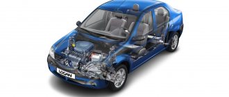
The Lada Granta car has a braking system (pipes, brake cylinders, vacuum booster, brake regulator, brake pads, etc.) similar to the Lada Kalina car. For effective and safe braking, the Lada Granta uses a diagonal, double-circuit piping system, which means that the first circuit blocks the wheels - the right front and left rear, and the second circuit - the left front and right rear. The front wheels are equipped with disc brakes, the rear wheels are equipped with drum brakes. The master cylinder is controlled through a vacuum brake booster, which increases the efficiency of operating the braking system by pressing the brake pedal. Depending on the configuration of the Lada Granta car, the braking system may be equipped with an anti-lock braking system (ABS). The Lada Granta has a handbrake that blocks the rear wheels (spreads the brake pads in the drums). The pads are moved apart through a system of levers by moving a steel cable attached to a lever located inside the car. The vacuum booster on the Lada Granta car (shown in Fig. 1) is of the diaphragm type. The diaphragm is the separating partition between the rarefied atmosphere created in the vacuum amplifier and external atmospheric pressure. The pressure difference reduces the force on the brake pedal. When the brake pedal is released, the vacuum and atmospheric chambers communicate with each other through a special valve.
Rice. 1. Diagram of the hydraulic brake system of the Lada Granta (without ABS): 1, 25 - brake mechanisms of the right front and left front wheels; 2, 24 — brake hose for supplying brake fluid to the right and left front wheels; 3,4, 15, 18, 21, 5,10,13,22,27 - hydraulic brake system pipelines; 6 — plastic reservoir of the brake master cylinder; 7 — main cylinder for hydraulic brakes; 8 — vacuum booster; 9, 30 — pipeline holders; 11 — flexible hose of the brake mechanism of the right rear wheel; 12, 17 - brake mechanism of the right rear wheel; 14, 31 — brackets for fastening flexible hoses; 16- flexible hose for the brake mechanism of the left rear wheel; 19 — elastic lever of the pressure regulator drive; 20 — pressure regulator; 23 – brake pedal; 24 — flexible brake mechanism of the left front wheel; 26 — tee of the circuit right front - left rear brake; 28 - tee of the left front - right rear brake circuit; 29 — bolts for securing tees
Features of the Lada Granta braking system with ABS are shown in Figure 2.
2. Diagram of the hydraulic brake drive of the Lada Granta (with anti-lock braking system): 1, 14, 22 — brackets for fastening flexible hoses; 2 — brake mechanism of the right front wheel; 3 — flexible hose of the brake mechanism of the right front wheel; 4, 5, 15, 18, 26 - pipelines of the right front - left rear brake circuit; 6, 10, 13, 27, 28 - pipelines of the left front - right rear brake circuit; 7 — plastic reservoir of the main brake cylinder; 8-vacuum booster; 9, 24 — pipeline holders; 11 — flexible hose of the brake mechanism of the right rear wheel; 12 — rear wheel brake mechanism; 16 - brake mechanism of the rear left wheel; 17 — flexible hose of the brake mechanism of the left rear wheel: 19 — brake pedal; 20-brake mechanism of the left front wheel; 21 — flexible hose of the brake mechanism of the left front wheel; 23 — main cylinder for hydraulic brakes; 25 - hydroelectronic ABS module
Rice. 3. Vacuum booster of the Lada Granta car: 1 - tip mounting flange; 2 — rod; 3 — diaphragm return spring; 4 — sealing ring of the master cylinder flange; 5 — main cylinder; 6 — amplifier pin; 7 — amplifier housing; 8 - diaphragm; 9 — amplifier housing cover; 10 - piston; 11 — protective cover of the valve body; 12-pusher; 13- pusher return spring; 14-valve spring; 15 - valve; 16- rod buffer; 17 - valve body; A - vacuum chamber; B - atmospheric chamber; C, D - channels Information about the principles of operation of the brake system components of the Lada Granta, in particular the main brake cylinder and the pressure regulator (the pressure regulator is installed only on cars without ABS) can be found in the article “Design features of the brake system of the Lada Priora car", the design of the units is similar .
Malfunction of wheel and brake cylinders can manifest itself as follows: - in the passage of brake fluid through the seals on the piston, and you may notice streaks around the perimeter of the mudguard. Leakage of brake fluid from a plastic reservoir located in the engine compartment; — it is also possible for the pistons to jam in the cylinder. Typically, jamming occurs in the extended position of the pistons. In this case, the pads wear out, the wheel slows down, and the car rolls poorly due to inertia, without engaging any gear. In both cases, the brake cylinder on a Lada Granta car must be replaced.
This article describes the operations for removing the brake cylinder, removing the brake mechanism assembly together with the brake cylinder, and the algorithm for removing the brake disc for its inspection, grooving or replacement. To carry out the operation you will need: a 12, 13, 17 mm wrench, a flat-blade screwdriver, a hex key.
Front and rear brake pads can be used up to a lining thickness of at least 1.5 mm, this is their smallest value (the value of at least 1.5 mm is the same for front and rear pads). With a smaller value of linings on the brake pads of the Lada Granta, it is possible for the rubber sealing rings installed on the piston to escape from the sealing field located on the cylinder cavity in the brake mechanism. Depressurization of the seal will result in the release of brake fluid into the external environment and will lead to breakdown and ineffective operation of the vehicle's brakes. In order to be guaranteed to replace old pads with new ones, change them without waiting for 1.5 mm of wear. Enough to replace 5 - 7 mm. The fact is that during prolonged operation in the limit position of the piston, the previously working sealing surfaces may become clogged with deposits, which will not allow the piston to return to its original working position in the brake cylinder, to a position corresponding to the thickness of the new brake pads. When replacing pads, replace them only as a set on both sides. This will allow you to avoid differences in grip when braking and, accordingly, the car pulling to the side.
Despite all the efforts of engineers equipping new cars with a wide variety of active driving assistance systems, many car owners do not like the work of some of them. The anti-lock braking system causes the greatest complaints from most drivers. It is designed to prevent the wheels from completely locking when braking the car, which helps to avoid loss of vehicle control and reduce the braking distance.
ABS is especially convenient for inexperienced drivers, but it has one feature - the ability to shorten braking distances is maintained only on level surfaces. If the road is dirty, bumpy, or snowy, the presence of ABS not only does not help to brake in time, but can also lead to an increase in braking distance. Therefore, the question becomes quite relevant for the driver - is it possible and how to disable ABS on a car. This can be done, but it is not at all as easy as it might seem.
content .. 5 6 7 8 ..Lada Granta (2019). Basic malfunctions of the brake system and their elimination
Increased brake pedal travel
| The rubber cuffs of the cylinders are swollen due to oil, gasoline, etc. getting into the brake fluid. | Replace cylinders, hoses, completely drain the brake fluid, flush the system with fresh fluid and bleed |
| Overheating of brake mechanisms | Allow the brakes to cool. Use only DOT-4 brake fluids in the system. Replace brake fluid promptly |
| The gap between the pads and the drum has been increased (the automatic gap adjustment device does not work) | Replace the wheel cylinder, bleed the system |
| One of the circuits of the service brake system does not work | Eliminate fluid leakage from the brake system, bleed the system |
| Increased (more than 0.15 mm) runout of the brake disc | Replace both drives |
Vibration when braking
| Vibration when braking | |
| Cause of malfunction | Elimination methods |
| Brake disc deformation | Replace both drives |
| Increased axial play of the wheel (severe wear of the front wheel bearings or loosening of the hub nut) | Tighten the wheel hub nut, replace the bearing if necessary |
| Brake drum ovality | Grind or replace the drum |
| Piston stuck in rear wheel cylinder | Replace cylinder |
| The brake pad lining has peeled off from the base. | Replace the pads (all on the same axis at the same time) |
| Rear brake pad tension spring is loose or broken | Replace the spring |
Car pulls or skids when braking
| Car pulls or skids when braking | |
| Cause of malfunction | Elimination methods |
| Wheel cylinder piston jamming | Replace cylinder |
| Blocked brake lines: tubes or hoses | Replace damaged tubes and hoses |
| Separation of the lining from the base of the brake pad | Replace the block (it’s better to have everything on the same axis at the same time) |
| Oiling of brake discs, drums, linings | Clean oily discs and drums and replace pads. Eliminate the cause of the oiling |
| An ice or salt crust has formed on the surface of the linings (in winter). The pads are wet | When starting to drive, check the brakes at low speed. In the rain and after driving through deep puddles, dry the brakes by lightly pressing the brake pedal. |
| Different tire pressures on left and right wheels | Set normal pressure |
| Significant difference in tire wear | Replace your worn tire |
| The pressure regulator drive is incorrectly adjusted | Adjust the drive |
| Pressure regulator faulty | Replace regulator |
| One of the circuits of the service brake system does not work (braking efficiency is significantly reduced) | Eliminate fluid leakage from the brake system, bleed the system |
| Brake disc deformation | Replace both drives |
| Wheel axial play (severe wear of the front wheel bearings or loosening of the hub nut) | Tighten the wheel hub nut, replace the bearing if necessary |
| Brake drum ovality | Grind or replace the drum |
| The strut shock absorber is faulty | Replace both shock absorbers |
| Uneven spring settlement of the front suspension | Replace both springs |
| Wheel alignment angles are incorrect | Adjust wheel alignment |
The car brakes poorly
| The brake pedal travel is within normal limits (the pedal is hard), but the car brakes poorly | |
| Cause of malfunction | Elimination methods |
| Wheel cylinder piston jamming | Replace cylinder |
| Blocked brake lines: tubes (due to dents) or hoses (due to swelling or delamination of rubber) | Replace damaged tubes and hoses |
| Oiling of brake discs, drums, linings | Clean oily discs and drums and replace pads. Eliminate the cause of the oiling |
| Complete wear of the brake linings (brake grinding) | Replace the brake pads (all on one axle at the same time) |
| An ice or salt crust has formed on the surface of the linings (in winter). The pads are wet | When starting to drive, check the brakes at low speed. In the rain and after driving through deep puddles, dry the brakes by lightly pressing the brake pedal. |
| Low quality lining material | Replace the pads (all on the same axis at the same time) |
| Severe corrosion of the brake disc (due to poor quality disc and/or lining material) | Replace drives |
| The brake pad lining has peeled off from the base. | Replace the pads (all on the same axis at the same time) |
| The pressure regulator drive is incorrectly adjusted | Adjust the drive |
| Pressure regulator faulty | Replace regulator |
| The vacuum booster is faulty or the hose connecting the booster to the receiver is leaking | Check the integrity of the hose, its fit on the fittings, and the tightness of the clamps. Check the amplifier's operation |
Incomplete release of all wheels
| Incomplete release of all wheels | |
| Cause of malfunction | Elimination methods |
| There is no free play in the brake pedal | Adjust pedal free play |
| The rubber cuffs of the cylinders are swollen due to oil, gasoline, etc. getting into the brake fluid. | Replace cylinders, hoses, completely drain the brake fluid, flush the system with fresh fluid and bleed |
| The master cylinder piston is jammed (due to corrosion, broken return springs) | Replace the master cylinder, bleed the system |
Braking one of the wheels when the brake pedal is released
| Braking one of the wheels when the brake pedal is released | |
| Cause of malfunction | Elimination methods |
| Wheel cylinder piston jamming | Replace cylinder |
| The rubber cuffs of the cylinders are swollen due to oil, gasoline, etc. getting into the brake fluid. | Replace cylinders, hoses, completely drain the brake fluid, flush the system with fresh fluid and bleed |
| Blocked brake lines: tubes (due to dents) or hoses (due to swelling or delamination of rubber) | Replace damaged tubes and hoses |
| Seizing of pads due to severe contamination of the caliper supporting surfaces | Remove the pads, clean the pad and caliper bearing surfaces |
| Rear brake pad lining peeling off | Replace the pads (all on the same axis at the same time) |
| Rear brake pad tension spring is loose or broken | Replace the spring |
| Deformation of the spacer bar, misalignment of the pads due to deformation of the brake shield | Straighten or replace spacer bar, brake shield |
| The attachment of the shoe guide to the steering knuckle is loose | Tighten the bolts |
| The parking brake is too tight, the cables are jammed in the sheaths | Adjust the tension of the cables, lubricate them with engine oil if the sheath is damaged or the cable wires are frayed, and if there is severe corrosion, replace the cable |
Insufficient effectiveness of the parking brake system
| Insufficient effectiveness of the parking brake system | |
| Cause of malfunction | Elimination methods |
| Incorrect drive adjustment | Adjust the drive |
| Drive cables are jammed in sheaths | Lubricate the cables with engine oil if the sheath is damaged or the cable wires are frayed, and if there is severe corrosion, replace the cable |
| Oily brake drums and linings | Clean oily discs and drums and replace pads. Eliminate the cause of the oiling |
| An ice or salt crust has formed on the surface of the linings (in winter). The pads are wet | When starting to drive, check the brakes at low speed. In the rain and after driving through deep puddles, dry the brakes by lightly pressing the brake pedal. |
When the parking brake lever is released, the wheels do not release the brakes.
| When the parking brake lever is released, the wheels do not release the brakes. | |
| Cause of malfunction | Elimination methods |
| Incorrect drive adjustment | Adjust the drive |
| After parking the car for a long time, the pads stuck (or froze) to the drum | While pulling the lever or cables, try to carefully (so as not to tear off the brake pads) turn the wheel. When parking the car, if possible, do not tighten the brake, but engage the gear |
content .. 5 6 7 8 ..
Is it possible to disable ABS without negative consequences?
It should be noted right away that if you disable the factory-installed system incorrectly, the on-board computer will record the fact of outside interference, which can lead to unnecessary questions during maintenance. If you have to contact the service under warranty, the fact that the ABS is turned off on its own may well become the reason for denial of warranty, and therefore free repairs.
To temporarily disable ABS, you can use the following algorithm of actions.
- Open the fuse box located next to the battery. In most cars, to disable the ABS, you will have to remove the 15-amp fuse, but before doing this, it is better to clarify this issue in the owner's manual for your specific car.
- After this, to check, you should briefly turn on the ignition - the brake and ABS lights should not go out, in addition, a sound signal will be heard. The ignition turns off.
- The mounting block itself is unscrewed and its bottom cover is removed.
- You will need to find the wire leading to the already removed fuse, cut it lengthwise and strip the ends by 1.5-2 cm.
- Before starting work, you need to purchase the simplest five-pin relay from a car store.
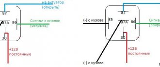
Before connecting, you should look at the contact diagram located on the case. You should start working with contacts 85 and 86, going to the winding. A wire leading to ground is connected to them, and the second will serve to supply a control signal from the ignition switch through the ABS switch off switch. Contact number 30 is connected to the wire coming from the fuse, and pin 88 is connected to the ABS. It is convenient to do this with wires prepared in advance, crimped on one side with the “mother” terminal. Subsequently, they will need to be installed in an empty relay block, and the switch off button is mounted anywhere in the cabin. How this is done in practice, and what the driver’s impressions are after this, can be seen in the video:
Temporary blocking of the anti-lock braking system
If you don’t want to perform all of the above steps, and the car is driven exclusively on hard and level surfaces, disabling the ABS may not be necessary. Before disabling ABS in the manner described above, you should be aware that under normal conditions it can actually reduce braking distances, leaving control of the vehicle to the driver. In addition, knowing some of the subtleties of control, in any emergency situation you can simply block its operation without first turning it off.
A fairly common situation when the anti-lock braking system prevents the car from stopping quickly is the need for emergency braking on a slippery, snowy road when an obstacle suddenly appears. In this case, when pressing the brake pedal does not lead to the desired result, and there is no time to turn off the system with the button, you should sharply pull the handbrake, blocking the rear wheels of the car. With this behavior of the driver, the system will allow you to fully depress the brake pedal, and you will be able to stop the car much faster. Thus, the question of whether it is possible to disable ABS should be accompanied by another one - whether this should be done, but each driver will have to decide it independently.
Attention!
How does ABS work?
The electronics regulate the brake force on all wheels, preventing them from locking when braking, but allowing the car to stop quickly. By braking sharply, the car will not lose stability.
If the system is out of order, or it is not installed on the car at all, then the wheels will lock during sudden braking. A strong skid may occur, especially in winter, or when turning. If the ABS is working properly, this will not happen. Even when turning, you can press the brake pedal sharply - there will be no skidding.
If the ABS light is on, the reason is a system malfunction. This is easy to check - accelerate to a speed of 40 km per hour and sharply press the brake pedal to the floor. If there is no pedal vibration and the wheels are skidding, then the ABS is not working.
If the system is working properly, you can sharply press the brakes and try to go around the obstacle. In this case, no skidding will occur. If the anti-lock braking system fails, the car will skid and hit this obstacle.
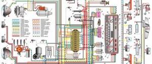
Notation system.
This diagram shows the address notation system.
Each device is assigned a number. And on each connection line in the diagram the number of the device where it goes is indicated, and through a slash (/) the designation of the contact of this device. If the connection is branched, more than 2 devices are galvanically connected, then addressing from the devices goes to a common bus for them, designated by the letter S and a number. This is done so that the communication line has one device address. After the connector, the device numbers of the circuit are independent of the device numbers before the connector. For ease of searching within the page, a fragment of the diagram, links are provided below. Return to the top of the page, Ctrl+Home keys.
List of elements of the electrical connection diagram of the front wiring harness
- 1 — right headlight;
- 2 — electric motor for washers;
- 3 — left headlight;
- 4 - starter;
- 5 — rechargeable battery;
- 6 — main fuse block;
- 7 - generator;
- 8 — sound signal;
- 9, 10, 11 — front wiring harness blocks to the instrument panel wiring harness blocks;
- 12 — air conditioning fan electric motor;
- 13 — electric fan of the engine cooling system;
- 14 — ABS hydraulic unit;
- 15 — right front speed sensor;
- 16 — left front speed sensor;
- 17 — automatic transmission controller;
- 18 — automatic gearbox;
- 19 — block for automatic gearbox;
- 20 — block to the automatic transmission selector switch;
- 21 — block to the automatic transmission speed sensor;
- 22 - air conditioning compressor.
List of elements of the electrical connection diagram of the ignition system wiring harness
- 1 — oil pressure warning lamp sensor;
- 2 - generator;
- 3 — throttle pipe with electric drive;
- 4 — coolant temperature sensor;
- 5 — ignition system wiring harness block to the instrument panel wiring harness block;
- 6 — solenoid valve for purge of the adsorber;
- 7 — pressure sensor of the air conditioning system;
- 8 — mass air flow sensor;
- 9 — crankshaft position sensor;
- 10 — oxygen concentration sensor;
- 11-controller;
- 12 — diagnostic oxygen concentration sensor;
- 13 — blocks of the wiring harness of the ignition system and the wiring harness of the ignition coils;
- 14 - noise suppression capacitor;
- 15 — ignition coils;
- 16 — spark plugs;
- 17 — nozzles;
- 18 — blocks of the wiring harness of the ignition system and the wiring harness of the injectors;
- 19-phase sensor;
- 20-knock sensor.
List of elements of the electrical connection diagram of the instrument panel wiring harness (Sheet 1.)
- 1,2 — blocks of the instrument panel wiring harness to the blocks of the front wiring harness;
- 3,4- blocks of the instrument panel wiring harness to the blocks of the rear wiring harness;
- 5 — lighting control module;
- 6 — ignition switch;
- 7 — on-board computer mode switch;
- 8 — windshield wiper switch;
- 9 — instrument cluster;
- 10 — light signaling switch;
- 11 — trunk lock drive switch;
- 12 — diagnostic block;
- 13 — block of the wiring harness of the instrument panel to the block of the wiring harness of the air supply box;
- 14 — rear window heating switch;
List of elements of the electrical connection diagram of the instrument panel wiring harness (Sheet 2.)
- 15 — alarm switch;
- 16 — brake signal switch;
- 17, 18 — blocks of the instrument panel wiring harness to the radio;
- 19 - rotating device;
- 20 — driver airbag module;
- 21 — sound signal switch;
- 22 — mounting block: K1 — relay for the electric fan of the engine cooling system;
- K2 - door lock relay;
- KZ - additional starter relay;
- K4 - additional relay;
- K5 - relay-interrupter for direction indicators and hazard warning lights;
- KB - windshield wiper relay;
- K7 - headlight high beam relay;
- K8 - sound signal relay;
- K9 - relay for low beam headlights;
- K10 — relay for turning on the heated rear window;
- K11-main relay;
- K12 - fuel pump relay;
- 24 — cigarette lighter;
- 25 — backlight lamp for the heater control panel;
- 26 — illuminator;
- 27 — block of the instrument panel wiring harness to the block of the ignition system wiring harness;
- 28 - controller;
- 29 — block of the instrument panel wiring harness to the block of the rear wiring harness 27;
- 30 — electronic accelerator pedal;
- 31 — additional resistor;
List of elements of the electrical connection diagram of the instrument panel wiring harness (Sheet 3.)
- 32 — heater electric motor;
- 33 — heater motor switch;
- 34 — control unit for the door lock system;
- 35 — relay (K16) of the electric fan of engine 3;
- 36 — relay (K15) of the electric fan of engine 1;
- 37 - compressor relay (K14);
- 38 — additional relay (K13) (reverse light relay);
- 39 — air conditioner switch;
- 40 — gear shift control drive;
- 41 — passenger airbag module;
- 42 — evaporator temperature sensor;
- 43 — block of the instrument panel wiring harness to the block of the rear wiring harness 3.
List of elements of the electrical connection diagram of the rear wiring harness
- 1,2- blocks of the rear wiring harness to the blocks of the instrument panel wiring harness;
- 3 — right side direction indicator;
- 4 — left side direction indicator;
- 5 — hand brake sensor;
- 6 — rear window heating element;
- 7 — interior lamp;
- 8 — switch in the driver’s seat belt;
- 9 — trunk lighting;
- 10 — electric fuel pump module;
- 11-light right;
- 12 — trunk locking motor;
- 13 — interior lamp switch;
- 14 - additional brake signal;
- 15 — left lamp;
- 16 — rear wiring harness block to rear left door wiring harness block;
- 17 — rear wiring harness block to rear right door wiring harness block;
- 18 — rear wiring harness block to the front right door wiring harness block;
- 19 — rear wiring harness block to the front left door wiring harness block;
- 20 — airbag control unit;
- 21 — rear wiring harness block to the wiring harness block for license plate lights;
- 22 — rear wiring harness block to instrument panel wiring harness block 3;
- 23 — right rear speed sensor;
- 24 — left rear speed sensor;
- 25 — driver’s seat belt pretensioner;
- 26 — passenger seat belt pretensioner;
- 27 - rear wiring harness block to instrument panel wiring harness block 29.
Wiring diagram of the front right door wiring harness
- 1 — block of the wiring harness of the front right door to the block of the rear wiring harness;
- 3 — right front lock;
- 4 — power window switch;
- 5 — blocks of the wiring harness of the front right door to the front right loudspeaker.
Wiring diagram for front left door wiring harness
- 1 — block of the wiring harness of the front left door to the block of the rear wiring harness;
- 2 — electric window lifter motor;
- 3 — left front lock;
- 4 — switch block;
- 5 — blocks of the wiring harness of the front left door to the front left loudspeaker.
The principle of operation of the system is simple: receiving data from the rotation speed sensors of all wheels and from the vehicle speed sensor, the control unit controls the rotation of each wheel and, if the wheel locks during braking, reduces the pressure in the corresponding brake circuit.
The ABS system ensures full control of the car during emergency braking, but does not lead to a reduction in braking distance.
Therefore, you need to maintain the correct distance.
On vehicles with an ABS system installed, a four-channel system is used.
The channels are connected according to a diagonal pattern.
The executive element of the anti-lock braking system is a hydraulic modulator. This is a complex assembly in which a hydraulic pump and solenoid valves are built in.
It is installed in the engine compartment.
The operation of the hydromodulator is controlled by an electronic unit installed on the hydromodulator.
The control unit also monitors the health of all elements of the ABS system.
Wheel speed sensors are installed in the front and rear brake mechanisms.