Electrical diagram of VAZ-2101, VAZ-2102
Electrical diagram of VAZ-2101, VAZ-2102
Repair and operation manual - Electrical diagrams of VAZ-2101 - VAZ-2107 - Electrical diagram of VAZ-2101, VAZ-2102 cars
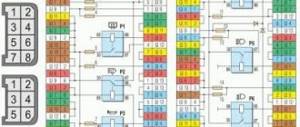
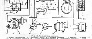
Electrical diagram of VAZ-2101, VAZ-2102 cars.
1 – headlights;
2 – sidelights; 3 – side direction indicators; 4 – battery; 5 – battery charge warning lamp relay; 6 – generator; 7 – starter; 8 – engine compartment lamp; 9 – spark plugs; 10 – oil pressure warning lamp sensor; 11 – coolant temperature indicator sensor; 12 – sound signals; 13 – ignition distributor; 14 – windshield wiper motor; 15 – brake fluid level warning lamp sensor; 16 – ignition coil; 17 – voltage regulator; 18 – windshield wiper switch located in the windshield washer pump; 19 – heater electric motor; 20 – glove box lighting lamp; 21 – additional resistor of the heater electric motor; 22 – plug socket for a portable lamp; 23 – parking brake warning lamp switch; 24 – brake signal switch; 25 – relay-interrupter of direction indicators; 26 – reverse light switch; 27 – fuse block; 28 – relay-interrupter for the parking brake warning lamp; 29 – windshield wiper relay; 30 – heater electric motor switch; 31 – cigarette lighter; 32 – lamp switches located in the rear door pillars; 33 – lamp switches located in the front door pillars; 34 – lampshades; 35 – ignition switch; 36 – instrument cluster; 37 – coolant temperature indicator; 38 – control lamp for high beam headlights; 39 – indicator lamp for external lighting; 40 – turn signal indicator lamp; 41 – battery charge indicator lamp; 42 – oil pressure warning lamp; 43 – control lamp for parking brake and brake fluid level; 44 – fuel level indicator; 45 – fuel reserve warning lamp; 46 – instrument cluster lighting lamp; 47 – horn switch; 48 – headlight switch; 49 – direction indicator switch; 50 – external lighting switch; 51 – instrument lighting switch; 52 – wiper switch; 53 – sensor for level indicator and fuel reserve; 54 – trunk lighting lamp; 55 – rear lights; 56 – license plate light; 57 – reversing lamp; 58 – plug blocks of the rear bundle of wires of the VAZ-2102 car; 59 – lampshade illuminating the rear part of the VAZ-2102 car. Quote
Windshield wiper VAZ 2101 Zhiguli
- Repair manuals
- Repair manual for VAZ 2101 (Zhiguli) 1970-1985.
- Wiper
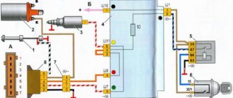
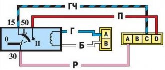
Windshield wiper connection diagram
| 1 – generator; 2 – battery; 3 – ignition switch; 4 – windshield wiper switch; 5 – windshield wiper relay; 6 – windshield wiper gearmotor; 7 – thermobimetallic fuse; | 8 – windshield wiper switch located in the windshield washer pump; 9 – fuse block; A – the order of conditional numbering of the plugs in the relay blocks and the wiper gear motor |
Since 1980, VAZ-2101, -2102 cars began to be equipped with a foot-operated windshield washer (see Fig. Windshield washer pressure pump ). This pump had an additional wiper switch 8, which was activated when the pump button was pressed.
Since 1982, a reusable thermobimetallic fuse has been installed in windshield wipers to protect the gearmotor from overloads.
↓ Comments ↓
1. Technical data
1.0 Technical data 1.1 Main overall dimensions of the VAZ-2101 car 1.2 Main overall dimensions of the VAZ-21011 car 1.3 Main overall dimensions of the VAZ-2102 car 1.4 Technical characteristics of the cars 1.5 Controls and monitoring devices 1.6 Ignition switch 1.7 Interior ventilation and heating controls
2. Operation and Maintenance
2.0 Operation and maintenance 2.1. Vehicle operation 2.2. Vehicle maintenance
3. Engine
3.0 Engine 3.1 Features of the device 3.2 Possible engine malfunctions, their causes and methods of elimination 3.3 Removing and installing the engine 3.4 Disassembling the engine 3.5 Assembling the engine 3.6 Bench tests of the engine 3.7 Checking the engine on a car 3.8. Cylinder block 3.9. Pistons and connecting rods 3.10. Crankshaft and flywheel 3.11. Cylinder head and valve mechanism 3.12. Camshaft and its drive 3.13. Cooling system 3.14. Lubrication system
4. Fuel system
4.0 Fuel system 4.1. Power system 4.2. Carburetor
5. Ignition system
5.0 Ignition system 5.1 Setting the ignition timing 5.2 Gap between the breaker contacts in the ignition distributor 5.3. Checking ignition devices on a stand 5.4 Possible ignition malfunctions, their causes and methods of elimination
6. Starting and charging system
6.0 Starting and charging system 6.1. Battery 6.2. Generator 6.3. Starter
7. Transmission
7.0 Transmission 7.1. Clutch 7.2. Gearbox 7.3. Cardan transmission 7.4. Rear axle
8. Chassis
8.0 Chassis 8.1. Front suspension 8.2. Rear suspension 8.3. Shock absorbers 8.4 Possible malfunctions of the chassis, their causes and methods of elimination
9. Steering
9.0 Steering 9.1 Features of the device 9.2. Inspection, check and adjustment of steering 9.3. Steering mechanism 9.4. Steering rods and ball joints 9.5. Pendulum arm bracket 9.6 Possible steering malfunctions
10. Brake system
10.0 Brake system 10.1. Features of the device 10.2. Checking and adjusting brakes 10.3. Clutch and brake pedal bracket 10.4. Main cylinder 10.5. Front brakes 10.6. Rear brakes 10.7. Rear brake pressure regulator 10.8. Parking brake 10.9 Possible brake malfunctions, their causes and methods of elimination
11. Electrical equipment
11.0 Electrical equipment 11.1. Electrical circuit diagrams 11.2. Lighting and light signaling 11.3. Sound signals 11.4. Windshield wiper 11.5. Heater electric motor 11.6. Control devices
12. Body
12.0 Body 12.1 Features of the device 12.2. Repair of the body frame 12.3. Paint and varnish coatings 12.4. Anti-corrosion protection of the body 12.5. Doors 12.6. Hood, trunk lid, bumpers 12.7. Body glazing and windshield washer 12.8 Instrument panel 12.8. Removal and installation 12.9. Seats 12.10. Heater
13. Features of repair
13.0 Features of repair 13.1. Car VAZ-21011 13.2 Cars VAZ-21013 13.3. Car VAZ-2102 13.4 Cars VAZ-21021 and VAZ-21023
14. Applications
14.0 Appendices 14.1 Tightening torques for threaded connections 14.2 Tools for repair and maintenance of vehicles 14.3 Used fuels, lubricants and operating fluids 14.4 Basic data for adjustments and control
Why are fuses needed?
“Where it is thin, it breaks” - this is exactly what folk wisdom says. In this case, it is quite suitable for determining the main task that a car fuse performs. To be more specific, the fuse serves to open an electrical circuit in which, for certain reasons, the current strength has increased significantly. This is necessary in order to avoid a short circuit, which can lead to fire and fire in the car. Each individual fuse in the block performs its specific task of protecting a specific unit or electrical device. Below is a list of the purposes of each fuse.
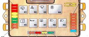
Fuse box
- 1 (16 A) – sound signal, brake light lamps, interior lamps, cigarette lighter socket for portable lamp.
- 2 (8 A) – heating electric motor, windshield wiper relay, windshield washer motor.
- 3 (8 A) – high beam of the left headlight, high beam indicator lamp.
- 4 (8 A) – high beam of the right headlight.
- 5 (8 A) – low beam of the left headlight.
- 6 (8 A) – low beam of the right headlight.
- 7 (8 A) – side light of the left sidelight, side light of the right rear light, size indicator lamp, instrument panel backlight lamp, license plate backlight, lighting lamp inside the trunk.
- 8 (8 A) – side light of the right sidelight, side light of the left rear light, cigarette lighter lamp, engine compartment lighting lamp.
- 9 (8 A) – coolant temperature sensor, fuel level sensor and reserve indicator lamp, oil pressure lamp, parking brake lamp and brake fluid level indicator, battery charge level lamp, direction indicators and their indicator lamp, reversing lamp, glove compartment lamp.
- 10 (8 A) – generator (excitation winding), voltage regulator.
Note: It is strongly recommended to install fuses of the correct rating. If you are supposed to install an 8 A fuse, therefore, such a fuse needs to be installed. Under no circumstances should it be replaced with a 16 A fuse.
It should be noted that the electrical circuit of the VAZ 2101 car is one-sided. This means that all negative wires from electrical devices and electrical units are connected to the car body, that is, to ground. As already mentioned, fuses play a protective role in the electrical circuit and if they burn out, they naturally need to be replaced. You can replace the fuse yourself, that is, with your own hands. But to do this, you must first determine that the fuse has actually blown. This can be done in two ways - visually and using a device (tester).
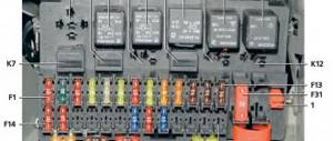
Circuit breakers
The photo above shows what a blown fuse looks like compared to a working device. The burnt out one is shown on the left side. The photo clearly shows that, compared to the working one, its jumper has burned out. However, a break in the electrical circuit may not always occur due to a burnt-out jumper. The insert knives of the device may simply oxidize and then it must be checked using a tester. If you cannot do this yourself, contact the service center.
Note: Before changing the fuse, it is necessary to find out the reason for its failure. And to do this, it is recommended to look at the entire circuit in which it is included. In particular, it is necessary to carefully examine the units and devices for the safety of which he is responsible.
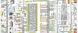
Electrical diagram of a VAZ 21013 car
Detailed explanation with photos, electrical diagram of fuse and relay blocks for VAZ cars.
1. Headlights. 2. Sidelights. 3. Side direction indicators. 4. VAZ 21013 battery. 5. Relay for the battery charge indicator lamp. 6. Relay for low beam headlights. 7. Relay for turning on the high beam headlights for VAZ 21013. 8. Generator for VAZ 21013. 9. Starter for VAZ 21013. 10. Engine compartment lamp. 11. Spark plugs. 12. Oil pressure warning lamp sensor. 13. Coolant temperature gauge sensor. 14. Sound signals. 15. Ignition distributor. 16. VAZ 21013 windshield wiper electric motor. 17. Brake fluid level warning lamp sensor. 18. Ignition coil. 19. Windshield washer electric motor 20. Voltage regulator VAZ 21013. 21. Heater electric motor VAZ 21013. 22. Glove compartment lighting lamp 23. Additional resistor for the heater electric motor 24. Plug socket for a portable lamp. 25. Parking brake warning lamp switch. 26. Brake light switch. 27. Relay - turn signal switch VAZ 21013. 28. Reversing light switch. 29. Fuse block. 30. Relay - parking brake warning lamp breaker. 31. VAZ 21013 windshield wiper relay. 32. Heater motor switch. 33. Cigarette lighter. 34. Lamp switches located in the rear door pillars. 35. Lamp switches located in the front door pillars. 36. Ceiling lamps. 37. Ignition switch. 38. Instrument cluster VAZ 21013. 39. Coolant temperature indicator. 40. Indicator lamp for high beam headlights. 41. Indicator lamp for external lighting. 42. Turn signal indicator lamp. 43. Battery charge indicator lamp. 44. Oil pressure warning lamp. 45. Indicator lamp for parking brake and brake fluid level. 46. Fuel level indicator. 47. Fuel reserve indicator lamp. 48. Instrument cluster lighting lamp 49. Headlight switch. 50. Turn signal switch. 51. Horn switch. 52. Windshield washer switch. 53. Windshield wiper switch. 54. External lighting switch. 55. Instrument lighting switch. 56. Level indicator and fuel reserve sensor. 57. Trunk lamp. 58. Tail lights. 59. License plate light. 60. Reversing light.
On the website avto-fresh.com you can find a diagram of the electrical equipment of a VAZ 21013 car, photos and descriptions of the blocks, as well as answers to questions about where it is located and what it is responsible for. The designation of electrical equipment is described in detail in the article.
The device of the VAZ 2101 generator
For its time, the design of the G-221 generator turned out to be quite successful. It was installed without modifications on subsequent models of the plant - VAZ 2102 and VAZ 2103. With proper maintenance and timely replacement of failed elements, it could be used for many years.
Structurally, the G-221 generator consists of the following main elements:
- rotor;
- stator;
- regulator relay;
- semiconductor bridge;
- brushes;
- pulley.
The G-221 generator is attached to the engine on a special bracket. This allows you to firmly fix the device and at the same time protect it from high temperatures.
Rotor
The rotor is the moving part of the generator. It consists of a shaft, onto the corrugated surface of which a steel sleeve and beak-shaped poles are pressed. This design serves as the core of an electromagnet rotating in two ball bearings. Bearings must be closed type. Otherwise, due to lack of lubrication, they will quickly fail.
The pulley can be considered either part of the generator or a separate element. It is installed on the rotor shaft and can be easily removed if necessary. When the engine is running, the pulley rotates by the crankshaft through the belt and transmits torque to the rotor. To prevent the pulley from overheating, there are special blades on its surface that provide natural ventilation.
Stator with windings
The stator consists of a number of special plates made of electrical steel. To increase resistance to loads in four places on the outer surface, these plates are connected by welding. A winding of copper wire is laid on them in special grooves. In total, the stator contains three windings, each of which consists of two coils. Thus, six coils are used to generate electricity by the generator.
Regulator relay
The regulator relay is a small plate with an electrical circuit inside, designed to control the voltage at the output of the generator. On the VAZ 2101, the relay is located outside the generator and is mounted on the rear cover from the outside.