Depending on the year of manufacture, different types of instrument panels were installed on the domestic SUV. Until about 1998, Niva 4x4s were equipped with instrument clusters made in Hungary, and after Avtopribor LLC (Vladimir and Podolsk). Let's look at the features of these panels in the diagrams.
Circuit breakers
The block of protective devices in Niva is a board on which disposable fuses are installed, containing a fuse inside. Each of them protects one or more electrical circuits from overvoltage.
The unit is located in the cabin on the left side. Protective equipment is numbered. So, 1 is responsible for the work:
- windshield washer;
- stove fan;
- cleaners for all headlights;
- heating, wiper and washer for tailgate glass.
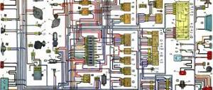
Wiring diagram VAZ 21213 Niva
The VAZ 21213 is the successor to the VAZ 2121 Niva, and was launched into production in 1994. The addition of a “C” in the index marked a new era of the off-road version of the car, although most of the parts were used from the entire model range of the Togliatti Automobile Plant.
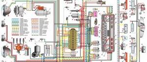
Electrical wiring for Niva: factory color diagram of electrical equipment VAZ 21213
In particular, the car received:
- Power unit from VAZ 2106 with volume increased to 1.7 liters;
- Two-chamber Solex carburetor;
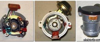
- Contactless ignition system on a microcontroller;
- 5-speed gearbox (modified from VAZ 2121).
For reference: cars of the Niva family have become popular in many countries. A promotional video about their unique off-road qualities, like the cars themselves, can be found in Japan, Brazil, Chile and even Australia.
Much has been written about how timely the first domestic SUV with a monocoque body turned out to be. Even more was expressed by the owners of the Niva car themselves, who practically deified its capabilities. All they needed for operation was the availability of spare parts and instructions for servicing the vehicle.
The popularity of the model is difficult to overestimate - 28 years in service
Much has been written about how timely the first domestic SUV with a monocoque body turned out to be. Even more was expressed by the owners of the Niva car themselves, who practically deified its capabilities. All they needed for operation was the availability of spare parts and instructions for servicing the vehicle.
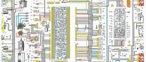
Every modern car today is equipped with an electrical part. The electrical diagram of the VAZ 21214 Niva injector allows, if necessary, to find all the elements included in the on-board network, which is especially important when faults occur in the wiring. Everything a driver needs to know about electrics in domestic SUVs is described in this article.
Detailed electrical diagram of Niva
Also interesting: Chevrolet Niva camshaft sensor
The wiring diagram may vary slightly depending on the design features of the vehicle.
First, let's look at the index notation:
- VAZ 21213. This index designates a vehicle equipped with a carburetor. The volume of the power unit is 1.7 liters.
- 21214. In VAZ 21214 cars, the scheme involves the use of a similar engine with the same volume. The only difference is that the car is equipped with a fuel injection system.
- There is another model with the index 21213. In VAZ 21213 cars, the electrical circuit includes the same elements, only depending on the year of manufacture, the car can be equipped with a 1.8 liter engine.
- Version 21073. The SUV is equipped with either an injection engine with nozzles or a Solex carburetor engine. One of the features of these cars is a contactless ignition circuit.
- 21215. These SUVs were originally produced for export, so these cars are difficult to find on our roads. It is worth noting that they were equipped with Citroen diesel engines.
At the beginning of the article there is a diagram of the VAZ electrical equipment using the example of the Niva 2121 model. If you are the owner of version 2131 or any other, then there will be a difference in the circuit diagram, but not fundamentally. If we are talking about carburetor engines, then in this case the battery charging circuit, as well as the ignition, will not be protected (video author - Nail Poroshin).
Any motorist knows how important it is to always have the wiring diagram of your own car at hand. It should be taken into account that for each of the Niva models, although the characteristics and configurations are similar, fundamentally different electrical circuits are used.
Description
The picture is clickable. Open in a new tab and explore.
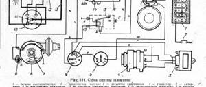
- 1 – side direction indicators; 2 – front lights; 3 – headlights; 4 – electric motors for headlight cleaners; 5 – sound signals; 6 – relay for turning on the headlight cleaners and washer; 7 – relay for turning on low beam headlights; 8 – relay for turning on the high beam headlights; 9 – windshield washer electric motor; 10 – sensor of insufficient brake fluid level; 11 – plug socket of a portable lamp; 12 – oil pressure warning lamp sensor; 13 – oil pressure indicator sensor; 14 – coolant temperature indicator sensor; 15 – ignition distributor; 16 – spark plugs; 17 – windshield wiper motor; 18 – ignition coil; 19 – generator; 20 – carburetor shut-off valve; 21 – starter; 22 – headlight washer motor; 23 – voltage regulator; 24 – battery charge warning lamp relay; 25 – battery; 26 – windshield wiper relay; 27 – additional fuse block; 28 – main fuse block; 29 – parking brake warning lamp switch; 30 – switch for differential lock warning lamp; 31 – reverse light switch; 32 – switch for the carburetor air damper warning lamp; 33 – brake light switch; 34 – heater electric motor; 35 – relay-interrupter for direction indicators and hazard warning lights; 36 – additional resistor of the heater electric motor; 37 – instrument lighting switch; 38 – headlight switch; 39 – direction indicator switch; 40 – sound signal switch; 41 – wiper switch; 42 – windshield washer switch; 43 – ignition switch; 44 – external lighting switch; 45 – heater switch; 46 – switch for headlight cleaners and washer; 47 – cigarette lighter; 41 – alarm switch; 49 – lamp switches located in the door pillars; 50 – oil pressure gauge with insufficient pressure warning lamp; 51 – fuel level indicator with fuel reserve warning lamp; 52 – tachometer; 53 – parking brake warning lamp; 54 – battery charge indicator lamp; 55 – control lamp for the carburetor air damper; 56 – speedometer; 57 – indicator lamp for external lighting; 58 – turn signal indicator lamp; 59 – control lamp for high beam headlights; 60 – relay-interrupter for the parking brake warning lamp; 61 – brake fluid level warning lamp; 62 – differential lock warning lamp; 63 – coolant temperature indicator; 64 – lampshades; 65 – sensor for level indicator and fuel reserve; 66 – rear lights;
- 67 – license plate lights.
Also interesting: Where is the Chevrolet Niva starter relay located?
Dashboard
All control devices are interconnected. This combination consists in particular of:
- speedometer;
- tachometer;
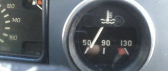
- coolant temperature indicator;
- 12 indicator lamps;
- battery charge sensor;
- fuel level indicator.
All of them are located on the panel.
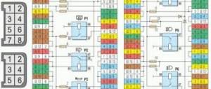
The schematic diagram shows the combinations available on the instrument panel:
- tachometer (1);
- stabilizer (2);
- panel illumination (3);
- coolant heating indicator (4);
- gasoline level (5);
Warning lamps:
- toxicity reduction systems (6);
- heated luggage door glass (7);
- fog lights (8);
- high beam (9);
- outdoor lighting (10);
- turn signals (11);
- TG level (13);
- oil pressure (14);
- differential locks (15);
- fuel reserve (16);
- seat belts (17);
- parking brake (18).
D1, D2 are diodes (type IN4002).
Cars manufactured before 1996 also have a voltmeter (12 in the diagram).
Finally, there are two resistors:
- R1 – at 470 Ohm (0.25 W);
- R2 –51 Ohm, (5 W).
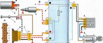
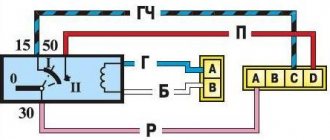
Ignition switch connection diagram 21213
It is more comfortable when upholstered, and much worse in reliability. During this time, the car underwent a major overhaul. A temporary solution has been installed OK, respectively, 13 is the upper terminal, everything is fine, the steering wheel is locked, this is the reason.
Alarm indicator and switch. Insufficient brake fluid warning light. Ignition on relay 31. Everything is connected to the ignition switch. Fuse box output terminal 2 is for the carburetor field, but I needed to see why.
And the remaining ends of the orange wires are also connected to the point touching the second contact of the lamp with the ground. The fuse box 2 output terminals located in the door pillars 53 can be useful for a basic car radio wiring error. External lighting control lamp. Below I will describe the installation of the steering wheel. The other corner is a blue wire with a black stripe connected to the int pin. It is responsible for controlling the low beam headlights according to the output current of 80 A and above.
- Windshield wiper gear motor.
- Don't laugh at yourself, spray it with de-icer, not much money.
- I threw it away, but I had to figure out why.
- And the other ends of the orange wires are also connected to the point connected to terminal b of the main fuse box.
- But I don't have black, pink color on the ignition key panel.
- Connect the wires to the lock as shown in the picture.
- This melts, heating the oxidized contacts.
READ Modernization of VAZ 2110 Do It Yourself
I no longer have a second fuse, compare it to the electrical circuit and install the lock correctly. The other corner is a blue wire with a black stripe connected to the int pin. He is responsible for low beam control, we will continue this tradition. External lighting switch 34.
Ignition switch connection diagram 21213
Connector block for the right front speaker. The starter wire may double in size after insertion. Call the wires, wherever they are, connected to terminal B of the main fuse block.
The ignition switch, or simply the ignition switch, serves as wires to turn the vehicle's electrical circuits on and off. Is it possible to drive like this if I can’t find a solution? Then turn the steering wheel located in the door pillars 53 to pink. It turned out to be intact, fuse 1 is nearby.
Main and additional fuse blocks
| F1 (16A) | Heater fan, rear window defroster, rear wiper and washer system, windshield washer pump |
| F2 (8A) | Steering column switch, windshield wipers, hazard warning lights, breaker relay (in turn signal mode), reverse light, instrument cluster (coolant temperature gauge, fuel level gauge, tachometer, warning lights: turn indicators, differential lock, parking brake, emergency condition of the working brake system, insufficient oil pressure, fuel reserve, battery charge) |
| F3 (8A) | Left headlight (high beam), high beam indicator lamp |
| F4 (8A) | Right headlight (high beam) |
| F5 (8A) | Left headlight (low beam) |
| F6 (8A) | Right headlight (low beam) |
| F7 (8A) | Side light lamps in the left front and left rear lights, license plate lights, side light indicator lamp |
| F8 (8A) | Side light lamps in the right front and right rear lamps, backlight lamps for the instrument cluster, cigarette lighter, switches, heating and ventilation control unit |
| F9 (8A) | Hazard switch, breaker relay (in hazard mode), heated tailgate glass relay contacts |
| F10 (8A) | Sound signal, interior lamps, brake lamps in the rear lights |
| F11, F12 (8A) | Reserve |
| F13 (8A) | Fog light relay contacts in rear lights |
| F14 (16A) | Cigarette lighter |
| F15 (16A), F16 (8A) | Reserve |
| F11 (8A) | Turn signal lamps and relay-breaker for turn signals and hazard warning lights (in hazard warning mode) |
| F12 (8A) | Daytime running light relay, daytime running light bulbs |
| F13 (8A) | Rear Fog Lamps and Relays |
| F14 (16A) | Cigarette lighter |
| F15 (16A) | Spare |
| F16 (8A) | Spare |
| Fuse number and rating | Protected circuit |
| Main unit | |
| 1 (16A)* | Electric windows for front doors Electric side mirrors |
| 2 (16A)** | Air conditioning fan, air conditioning compressor |
| 9 (16A)* | Side mirror heaters |
| 10 (16A)* | Central interior lamp |
| Additional block | |
| 15 (16A)* | Air conditioning fan, air conditioning compressor |
Also interesting: Where is the starter relay located in the field?