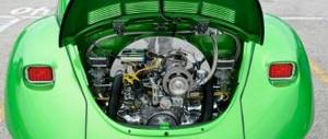
Passenger cars are equipped with different types of engines; power units may differ in volume, power, and design.
- 1 Engine piston rings
- 2 Thermal clearance of piston rings
- 3 VAZ piston rings
- 4 Signs and causes of wear (breakage) of piston rings
- 5 Piston ring sizes: table (VAZ)
- 6 Replacing piston rings
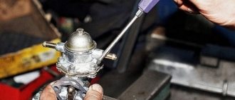
- 7 Decarbonization of piston rings
Depending on the manufacturer, each engine has its own specific resource - the most basic serious failures are considered to be failure of the crankshaft or piston group.
If oil consumption in an engine increases, the most common reason for this is worn or broken piston rings; replacing them is quite labor-intensive work, and also requires certain plumbing skills.
Engine piston rings
In an internal combustion engine (ICE), piston rings (PR) serve as a seal between the cylinder walls (liners) and the piston, due to which compression is created in the cylinders. If you forget to put the PC into the engine during assembly, the engine will not start, since the necessary compression of the working air-fuel mixture will not be ensured.
In passenger cars, three rings are standardly installed on each piston - two compression rings and one oil scraper ring, and oil scraper rings can be stacked, that is, consist of several elements. Compression piston rings (CPRs) are used to create compression in the cylinders and are always made of high-strength cast iron with various additives. The upper CPC has the greatest strength, since it operates in the most severe temperature conditions and experiences maximum loads.
Engine oil piston rings (OPRs) are needed to drain oil from the cylinder walls; if the rings do not perform their function, the engine will consume oil. MPKs can be either cast iron or steel, and cast iron PCs are almost always made in one piece, but steel oil scraper rings can only be assembled (composite). Steel MPC for one cylinder consists of:
- two spring steel rings;
- axial expander;
- radial expander.
Causes of gasket damage
The cylinder head gasket is a disposable element and must be replaced when disassembling the engine.
The structure of the cylinder head gasket consists of several layers:
- cardboard;
- fibers;
- traffic jams;
- steel edging.
When operating a vehicle, it is necessary to periodically inspect the VAZ-21124 engine and check the condition of the gasket, damage to which can lead to premature overhaul of the vehicle.
Thermal clearance of piston rings
PCs are spring discs with one cut - when installed on the piston, they expand, and in the sleeve they are pressed tightly against its walls. In order to achieve maximum compression of the working mixture, the cylinder walls must be as smooth as possible (without defects), and the shape of the internal cavity must be perfectly round. On the piston, the PCs are placed in special grooves, moreover, they are not seated tightly, and on a cold piston they move freely in the grooves.
Piston rings have thermal clearances:
- between PC and groove;
- at the junction.
The clearances must be certain; if they are larger or smaller than the required value, the piston group will quickly fail. One should take into account the fact that when heated, the metal expands, and if the thermal gap of the PC is too small, the piston group will begin to overheat. With large gaps, tightness is not ensured and power losses occur.
For passenger cars, as a rule, the following clearances are established:
- between the grooves and the PDA - from 0.02 to 0.08 mm (for the upper ring the gap should be slightly larger);
- between grooves and MPC – from 0.05 to 0.06 mm;
- at the junction - from 0.25 to 0.5 mm.
As wear occurs, the gaps in the PC increase, and they should not exceed:
- between the ring and the groove – 0.15 mm;
- at the junction – 1.0 mm.
VAZ piston rings
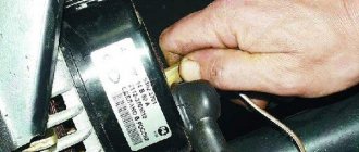
The Volzhsky Automobile Plant produces engines for front-wheel drive and rear-wheel drive cars; piston rings for VAZ engines were originally supplied by the Michurinsky plant. The Michurins produced a lot of defects in their products, and since 1986, their own production was established in Tolyatti. Currently, there are many different manufacturers that produce PCs for VAZ engines, in particular, these are:
Currently reading
Meet: Eneos 5W-30 oil
Motor oil for two-stroke engines
- AVTOVAZ (Tolyatti);
- STK (Samara);
- GOETZE (Germany);
- MAHLE (Germany);
- NPR EUROPE (formerly SM, Japan).
Signs and causes of wear (breakage) of piston rings
On VAZ cars, the engine wears out during operation, and the PCs also fail. Rings can:
- break into two or more parts;
- wear out in thickness;
- have general wear and tear.
Parts often break down due to overheating of the internal combustion engine; in this case, compression in the cylinders decreases and the engine loses power. Signs of a faulty PC are:
- bluish smoke from the muffler pipe, especially often it appears after a long period of idling when the gas pedal is sharply pressed;
- increased engine oil consumption;
- drop in power, the motor stops pulling;
- coking of spark plugs.
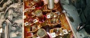
If there are signs of a malfunction in the piston group, the piston rings are replaced first. But replacing a PC does not always give the desired effect; often after repair the engine continues to smoke and consume oil. The reason for this is simple - there is wear in the cylinders themselves. In the block, the liners usually wear out unevenly - they take on an oval shape; due to wear, the piston rings do not fit tightly to the cylinder walls and do not provide a tight seal.
Piston ring sizes: table (VAZ)
VAZ-produced cars are equipped with engines of the following types:
- 2101/2103/ 2105/2106 (VAZ classic);
- 21213/21214/2130 (Niva);
- 2108/21083 (VAZ 2108-09-099);
- 2111/2112 (VAZ 2110-11-12);
- 21114 (VAZ 2113-14-15);
- 11186 (Lada Granta);
- 11194 (Lada Kalina).
There are also many other modifications of internal combustion engines, all VAZ engines are four-cylinder in-line, with a total number of valves of 8 or 16. VAZ engines have several standard cylinder sizes:
- 76 mm;
- 79 mm;
- 82 mm.
For each size, a repair increase of 0.4 and 0.8 mm is provided; factories produce repair pistons and rings of the first and second repair sizes. Piston rings with a diameter of 76 millimeters are available for engines:
- 2101;
- 2103;
- 2108;
- 1111(Oka).
The first repair size of the PC for these motors is 76.4 mm, the second repair size is 76.8 mm. Pistons, as well as 79 mm piston rings, are produced for internal combustion engines:
- 21011;
- 2105;
- 2106;
All these motors also have two repair PC sizes - 79.4 mm (first repair) and 79.8 mm (second repair). The most common PC size is 82 mm; many modern VAZ cars use a piston group of this exact size. Piston ring diameter 82 mm can be found on engines:
- 21083;
- 21213;
- 21214;
- 2130;
- 2123(Chevrolet Niva);
- 2111;
- 21114;
- 11183 (Kalina and Granta);
- 2112;
- 21124;
- 21126(Priora);
The VAZ internal combustion engine also has deviations from the typical dimensions, for example, on the 11194 engine with a volume of 1.4 liters, pistons and PCs with a diameter of 76.5 mm are installed; this internal combustion engine is equipped with the Ladv Kalina. Also there is a custom 1800cc power unit? VAZ-21128 with a nominal cylinder diameter of 82.5 mm, but the engine is not mass-produced by AvtoVAZ.
How to install rings on the piston of a VAZ 2110
Sooner or later, your engine will wear out and will require either a replacement of the piston rings or the piston as a whole.
It seems that changing piston rings is an ordinary task, accessible to anyone who is more or less familiar with the structure and operating principle of a primitive four-stroke engine. But, unfortunately, people are afraid to spend 15 minutes of their incredibly precious time reading literature and stuff everything into the engine according to the principle (and that’s how it was. It’ll probably work). Well, the flag is in your hands and contact the service as soon as possible.
Well, for those who care how their engine will work after a rebuild, you should read this article.
So, we take the piston and see 3 grooves for installing piston rings. There are no limit stops on 4-stroke engines, like on 2-stroke engines, for example.
There are two types of piston rings on 4-stroke engines. The first two, which are installed in the two upper grooves, are compression. Even from the name it is clear that they are responsible for the presence of compression in your engine and must retain the gases formed at the moment of the outbreak due to the combustion of fuel in the combustion chamber.
The next three rings are oil scraper rings. Here, too, their purpose is immediately clear. They are responsible for skimming off the oil that coats the cylinder walls as the piston returns down. If these rings leak, then the oil will remain on the cylinder walls, and this can lead to the fact that the engine will begin to consume oil, and, naturally, smoke will appear.
How to install first? Yes, in principle, as they were from the factory, in the same order, but to avoid mistakes we show them again.
Initially, we install the main oil scraper ring: the one that has a wave-like structure. Installing it could not be easier, since it is the most elastic of all.
Next, install the upper and lower THIN oil scraper rings. They are a little harder, but there shouldn't be any problems installing them either.
Now we install the piston compression rings: those that are thicker and “harder”. First install the lower one, then the upper one. They are a little more difficult to place as they are less elastic and harder. You are unlikely to be able to break them, but with completely crooked hands, bending them couldn’t be easier.
Do you think that's all? No!
The fact is that the rings still need to be correctly positioned on the piston so that the ring locks (the cut location) do not fall on each other. Simply put, it is necessary that the cut of the lower ring is not located directly above the cut of the upper ring.
We start with the upper piston rings.
We place the lock of the lower ring in the middle above the cavity of a valve, for example, an intake valve (it can also be an exhaust valve, there is no difference).
We place the lock of the upper ring strictly on the opposite side from the lower ring. Accordingly, if the lock of the lower ring is above the cavity under the intake valve, then the lock of the upper ring is above the cavity under the exhaust valve.
Now let's move on to the oil scraper rings. These rings need to be positioned in exactly the same way so that no lock matches. Therefore, we place the upper ring above the hole for the piston pin, on the right side.
We place the second one (the one at the bottom) on the opposite side, also approximately in the middle of the hole for the piston pin.
Replacing piston rings
On VAZ cars, as well as on all other models of passenger cars, it is advisable to change only the piston rings only if:
- there is no exhaust in the cylinders;
- there are no signs of damage to their inner surface.
If the liners are significantly worn, they need to be bored, and if the last size was already used before, the cylinder block needs to be relined. You can replace the PC on any VAZ engine without removing the internal combustion engine; this will require removing the cylinder head and oil sump. PCs are replaced if the gap at the joints does not exceed 1 mm.
For example, let's consider replacing piston rings on a VAZ-2114 car with an 8-valve internal combustion engine; such work must be carried out on a pit or a car lift:
- turn off the ignition, put the gearbox in neutral, disconnect the negative terminal from the battery;
- drain the antifreeze, remove the air filter housing along with the pipe (injector corrugation);
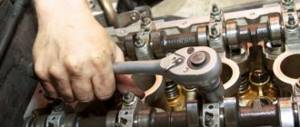
- remove the valve cover, camshaft, loosen the timing belt and move it to the side;
- disconnect the wires and cooling system pipes from the cylinder head, unscrew the head bolts;
- unscrew the nuts of the exhaust pipe of the muffler;
- We completely free the cylinder head from all fasteners that prevent it from being removed, and we remove the cylinder head;
- if there is protection under the engine, remove it;
- place a container under the engine sump, unscrew the plug on the crankcase, drain the oil;
- remove the lower hatch of the gearbox housing (three bolts);
- Using a 10 mm wrench or a socket wrench, unscrew all the oil pan bolts;
- dismantle the pan, remove the oil receiver;
- Unscrew the connecting rod nuts, remove the lower connecting rod caps, and carefully knock the pistons and connecting rods upward. Pistons should be knocked out through a soft metal drift or through a wooden block. First, you need to carefully knock out the connecting rod bolt without damaging the threads on it, then place the drift on the end of the connecting rod - in no case should you hit the bearings or the seat underneath them;
- It is recommended to remove the connecting rods one at a time, and immediately attach the caps to them; the caps should not be confused with each other, they are placed back strictly in their places, and a lock to the lock is required;
- remove the PC from the pistons, use a piece of the old ring to clean the piston grooves to bare metal. Be sure to check the cleanliness of the groove all around; there should be no coke left in it;
- We install new rings in the grooves, start with the lower MPC, then install the middle compression PK, and lastly the upper one. For installation, you can use a special device, but it is still more convenient to install the rings by hand. If the MPCs are cast iron, they cannot be bent along their axis, they can only be carefully moved apart. Compression rings also need to be bent carefully, to a minimum;
- we install the piston in place using a special mandrel, hammer it in with a wooden hammer handle or a brass or bronze drift;
- We install one piston-rod at a time, and immediately attach a connecting rod cap to each one. The connecting rod nuts should be tightened with a torque wrench, force - from 4.5 to 5.5 kg;
- then we put everything in place - the oil receiver, the engine sump, the cylinder head. We fill the radiator with antifreeze, oil into the crankcase, and start the engine to check. After replacing the PC, the internal combustion engine may initially smoke and consume oil - the engine needs to be run in for approximately 2 thousand km. It happens that despite the seemingly normal condition of the liners, the internal combustion engine continues to smoke even after replacing the rings after break-in. In this case, you will have to bore the cylinders and install a repair piston group.
Rear doors of VAZ 2110, 2111, 2112
Assembly of rear doors of VAZ 2110
I tried to assemble the rear doors. Everything needs to be done, from gluing the guides onto the new glass and ending with installing the new velvet covers. This entry most likely did not exist here now, if everything immediately turned out as it should have. And so, about everything - in order)
1. First, of course, is the procedure for preparing the parts. I had to bathe the internal locks a little in white spirit to remove the old grease mixed with road dust.
Locks
I didn’t open the door locks because they don’t seem to be removable. I blew everything out thoroughly with compressed air. Then I applied lubricant (Ciatim-203) with a large bristle brush.
2. ESP right\left production “Electrical machine-building Mede in Kirov. Window regulators manufactured in 2001, the drive is completely in a metal case.
Link to the list of products and other ESP (Kalina, Priora, etc.) www.lepse.com/products/19/ I have a modification of EPS-4.
Mechanism:
I looked at the gear and there is no visible wear after 12 years. This means you can add a little lubricant and live in peace. The gearboxes are screwed on tightly and I couldn’t remove them. All bolts are sealed with some kind of elastic sealing paint.
3. When everything is ready, you can rush to collect) There are a lot of instructions on what and how to spin on the Internet, and actually there is nothing special.
— We lower the glass in the door, turn it around and raise it up. Everything is in its place. — The space in the door is free, you can hang a padlock: an internal lock with rods, an external lock. We check, we pull. Working means excellent. — We install the lift (through the technological hole), adjust the position. We screw the guide to the glass strip. We achieve smoothness and uniformity of movement. The ESP was powered by a 12v power supply. Setup takes a little longer because... It is more difficult to check the lifting force than with a manual lift.
right left sliding glass guides
Standard lock drives were replaced with starlines
The lock rod had to be shortened by about 1cm, because the body of the new drive is slightly longer.
When checking the opening and closing, it turned out that this lock was a little jammed.
We'll have to replace it later; one bolt was broken off. I had to weld it to it, and it ended up leaking onto the body... then the grinder... basically, I lost it. Something has started inside due to the temperature and is now a little tight to snap open.
4. Put the outer velvet covers in place. To ensure that everything is done correctly, they are from Priora. The internal ones will be new, native decimal ones.
All is ready. Where necessary, I glued it with bitoplast and madeline so that nothing would rattle or rattle on the road.
So I spent one day on the right door, and did the left one the next day. At the beginning, everything went as normal, absolutely nothing new, until I got to installing the guides... Then a jamb popped up, for some reason the glass was sagging a lot on one side (((I turned the spit, I tried everything, everything doesn’t run smoothly.
In general, if you remove the short guide, everything is fine, the gaps on the right and left are the same, the glass rises smoothly. This one:
My photos:
It squeezes the velvet so tightly
There is already visible wear on the seal, the colored mark on the glass is soil. It was touched before the velvet cover was installed.
if you remove the velvet it will reach the metal
I'm already inclined to think that maybe the glass they sold was crooked, although it's original.
Elimination of distortion of the glass of the rear left door of the VAZ 2110
Yesterday I described a problem that arose during the assembly process. I struggled with this problem for several days. And this morning I decided to do some more shamanism and everything worked out. The truth is I still don’t know what’s the matter. Maybe it’s true that the glass they sold was not even.
Everything was fixed with the help of one washer (1mm thick), I placed it between the glass fastening bar and the seat to the ESP. As a result, the glass fell into place; the gap from no increased to 3-4 millimeters)
Here are photos of this case:
Puck
This is normal!
Well, in one go I twisted the fasteners, added flat washers; they weren’t there; they were locking ones with teeth.
Something like this. I am glad that all the seals are in place, the velvet is in agreement with the glass sealing rubber.
This is how they turned out
https://www.drive2.ru/l/2936183/, https://www.drive2.ru/l/2936407/, https://www.drive2.ru/l/2943549/
next article:
Tuning, sound insulation and modification of the dashboard of VAZ 2110, 2111, 2112
Contents of the article: 1. Do-it-yourself tuning of the VAZ 2111 dashboard 2. Soundproofing the VAZ 2110 dashboard 3.
Rating 0.00 [0 Vote(s)]
Decarbonization of piston rings
If the engine starts to smoke, there is a possibility that there are rings stuck in the piston grooves. Nowadays, there are many different modern means for decarbonizing piston rings, and many drivers use them to restore engine performance. Among the most popular compositions are:
- Nitrox Power;
- LAVR ML-202;
- Titanium;
- LIQUI MOLY;
- WYNN'S.
Motorists believe that if the engine starts smoking, you need to use a decarbonizer, and the engine will work as before, without oil consumption and without smoke. Indeed, sometimes these remedies help, but only in cases where the motor has stood motionless for a long time (for example, after winter), and moisture has accumulated in it. If the car is subject to long-term preservation (put in a garage for winter storage), you should remove the spark plugs and pour oil into the cylinders, and plug the spark plug holes with plugs. With such prevention, the spark plugs will not become damp and rust will not accumulate on the sleeves.
But if, after all, a forgetful car owner has not taken preventive measures, you can use a decarbonizer. We get rid of rust in cylinders as follows:
- pull off high-voltage wires;
- unscrew all spark plugs;
- rotate the crankshaft so that all pistons are in the middle position;
- pour 45 ml of liquid into each cylinder, install spark plugs;
- leave the cylinders to “soak” for 6-7 hours;
- why do we turn out the spark plugs, turn the starter a few revolutions so that all the dirt flies out of the engine;
- We put the removed parts back in place and start the engine. At first it may smoke a lot, but then the smoke will go away.
Car owners should remember that decarbonization is not a panacea for all ills, and if the piston rings are worn out, then only replacing them will help.
VAZ 2111 engine assembly
Assemble engine as follows.
Place a clean cylinder block and screw the missing studs into it. Install the generator mounting bracket and secure it with two bolts.
Lubricate the bearing shells and thrust half rings of the crankshaft, as well as the pistons and oil seals with engine oil. When assembling the engine after repair, install new crankshaft oil seals.
Rice. 1. Installing the crankshaft thrust half-rings into the middle main bearing sockets
Install liners with a groove in the 1st, 2nd, 4th and 5th seats of the cylinder block, and liners without a groove in the 3rd seat of the cylinder block and in the main bearing caps. Place the crankshaft in the main bearings and insert the thrust half rings into the seat of the middle main bearing (Fig. 1).
WARNING
The half rings should have their grooves facing the thrust surfaces of the crankshaft (an anti-friction layer is applied to the surface of the half ring on the side of the grooves). A cermet half-ring (yellow) is placed on the middle support of the crankshaft on the flywheel mounting side, and a steel-aluminum half-ring on the opposite side.
Install the main bearing caps in accordance with the marks that are marked on their outer surface. Rotate the caps so that the marks on each of them are on the side where the generator is installed. Tighten the cover bolts.
Rice. 2. Checking the axial free play of the crankshaft
Check the free axial movement of the crankshaft. To do this, turn the cylinder block with its back side up and install a stand with an indicator on it so that the indicator leg rests against the crankshaft flange. Moving the shaft up and down (for example, with screwdrivers), measure the free axial movement of the shaft with an indicator ( Fig . 2.). It should be in the range of 0.06-0.26 mm. If the stroke is greater, then bring it back to normal by replacing the old half-rings with new ones or installing half-rings of increased thickness.
Rice. 3. Crankshaft rear oil seal holder.
Arrows indicate protrusions for
centering the holder relative to the crankshaft flange
Using mandrel 67.7853.9571, press the rear crankshaft oil seal into the holder (Fig. 3.). Place the holder with the oil seal on the mandrel 67.7853.9572 and move it from the mandrel to the crankshaft flange. Place a gasket under the holder and attach it to the cylinder block with bolts and spring washers
Rice. 4. Blocking
flywheel clamp 67.7820.9526
Install the flywheel on the crankshaft so that the mark (cone-shaped hole) near the rim is opposite the axis of the crankpin of the fourth cylinder. Install the flywheel washer and bolts. Lock the flywheel with clamp 67.7820.9526 (see Fig. 4.) and tighten the fastening bolts. Apply UG-6 sealant to the flywheel mounting bolts before installation. To ensure that the sealant adheres reliably, degrease the bolts and threaded holes in the crankshaft before applying it.
Rice. 5. Installation of the piston with piston rings into the cylinder using an adjustable bushing 67.7854.9519
Select pistons to cylinders by class and one weight group and assemble the pistons with connecting rods. Using the adjustable bushing 67.7854.9519, insert the pistons with connecting rods into the cylinders (Fig. 5).
WARNING.
The hole for the pin on the piston is offset from the axis by 1.2 mm, therefore, when installing the pistons into the cylinders, the arrow on the piston bottom should face towards the camshaft drive.
Install the bearings into the connecting rods and connecting rod caps. Install the connecting rods and caps onto the crankshaft journals and tighten the connecting rod bolts. The connecting rod caps must be installed so that the cylinder number on the cap is opposite the cylinder number on the lower end of the connecting rod.
Using mandrel 67.7853.9580, press the crankshaft front oil seal into the oil pump cover. Fill the oil pump with some engine oil and rotate the drive gear several times. Install the oil pump with the crankshaft front oil seal on the mandrel 67.7853.9580 and turn the drive gear to a position so that it can be placed on the crankshaft journal. Move the pump from the mandrel to the shaft, install a gasket under the pump and attach it to the cylinder block.
Rice. 6. Oil pump guide pins
For proper installation of the pump, two guide pins are pressed into its housing, which must fit into the corresponding holes in the cylinder block.
Rice. 7. Installation of the oil pump: 1 - oil pump; 2 — oil pump gasket; 3 — oil pump receiver; 4 — crankcase gasket; 5 - crankcase; 6 - crankshaft position sensor
Insert an oil drain pan with an O-ring into the hole in the oil pump, attach it to the oil pump and to the cover of the second main bearing of the crankshaft (see Fig. 7.). Install oil sump 5 with gasket 4 and secure it.
O-ring with engine oil and install the oil filter by hand screwing it to the fitting on the cylinder block.
Rice. 8. Bushings for centering the head on the cylinder block
Insert two centering sleeves into the cylinder block (Fig. 8.) and install the cylinder head gasket over them. With a correctly installed gasket, the oil passage hole (edged with copper tape) should be in the area of the 5th cylinder head bolt.
Rotate the crankshaft so that the pistons are in the middle of the cylinders.
Install the cylinder head along the centering bushings. Tighten the cylinder head bolts in a certain sequence. To ensure a reliable seal and prevent the bolts from being tightened during vehicle maintenance, tighten the cylinder head bolts in four steps:
1st step - tighten the bolts to a torque of 20 N m (2 kgf m);
Step 2 - tighten the bolts to a torque of 69.4-85.7 N m (7.1-8.7 kgf m);
Step 3 - tighten the bolts 90°;
4th step - tighten all the bolts again by 90°;
Rice. 9. Cylinder head bolt
WARNING
The cylinder head mounting bolts may only be reused if they have been extended to a length L of no more than 135.5 mm (see Fig. 9). If the bolt is longer, replace it with a new one.
Before assembling the engine, lubricate the threads and bolt heads in advance by dipping them in engine oil. Then allow excess oil to drain by letting the bolts sit for at least 30 minutes. Remove oil or coolant from the cylinder head bolt holes in the cylinder block.
Insert the coolant pump with the gasket into the cylinder block socket. Install the rear timing belt cover and attach it together with the pump cover to the cylinder block. Additionally, attach the cover with a bolt to the cylinder block and a nut to the stud on the cylinder head.
Insert segment keys into the slots at the front ends of the crankshaft and camshaft and install the toothed pulleys. Having blocked the camshaft pulley from turning, secure it with a bolt and washer.
WARNING
It is prohibited to replace the flywheel mounting bolts with the camshaft pulley mounting bolt and vice versa due to their different coating. The flywheel mounting bolts are phosphated, and the camshaft pulley mounting bolt is oxidized.
Rice. 10 . Checking the alignment of the timing marks on the camshaft pulley and the rear protective cover
Using tool 67.7811.9509, turn the camshaft until the mark on the pulley aligns with the installation lug on the rear cover of the toothed belt (Fig. 10.)
Fig. 11. Checking the alignment of the timing marks on the crankshaft pulley
and the oil pump cover.
Turn the crankshaft towards a smaller angle of rotation until the installation mark on the pulley aligns with the mark on the oil pump cover ( Fig . 11). You can turn the crankshaft using a wrench using a bolt temporarily screwed into the front end of the crankshaft.
Install the tension roller with a spacer washer and secure it in the position of minimum belt tension.
Place the timing belt on the camshaft pulley and, while tensioning both branches of the belt, place the left branch behind the tension roller and put it on the coolant pump pulley. Place the belt on the crankshaft pulley and lightly tension it with the tension roller, turning the roller counterclockwise. When installing the belt, avoid sharp bends.
Turn the crankshaft two turns in the direction of rotation and check that the alignment marks match (see Fig. 10 and 11). If the marks do not match, then loosen the belt tension, remove it from the camshaft pulley, turn the pulley to the required angle, put on the belt, slightly tension it with the tension roller, turn the crankshaft two turns again and check that the alignment marks match.
If the marks match, adjust the belt tension as described in the “Camshaft and its drive” subsection.
Adjust the clearances in the valve mechanism as indicated in subsection. "Cylinder head". Install the front timing belt cover and secure it with bolts. On the rear side of the engine, attach a plug with a gasket to the cylinder head and to the bearing housing.
Carefully place the gasket into the groove of the cylinder head cover along the entire perimeter. Install the cover on the cylinder head, put the rubber bushings on the studs and attach the nuts and washers. If the bushings show signs of destruction, replace them with new ones. Tighten the nuts evenly in several steps until the washer rests on the stud. Remember that the tightness of the cover depends on the thoroughness of all installation operations.
Wrap the spark plugs and coolant temperature gauge and oil pressure warning light sensors into the cylinder head. Install the ignition module with bracket and high-voltage wires.
Install the cooling jacket outlet pipe with a gasket on the cylinder head and secure it with two nuts. Screw the temperature sensor into the pipe. Install the gasket and attach the coolant pump inlet pipe flange to the cylinder block. Place the hoses leading to the thermostat onto the pipe and supply pipe, install the thermostat and secure the hoses with clamps.
Install the crankcase exhaust ventilation hose and secure it with clamps to the pipes of the block and cylinder head cover. Install the oil level indicator.
Rice. 12. Installation of the receiver and inlet pipe: 1 - support bracket; 2 — inlet pipe; 3 — receiver gasket; 4 - receiver; 5 — bracket for the tip of the accelerator drive cable; b — bracket; 7 — exhaust manifold screen; 8 — support bracket
Place gaskets on the cylinder head studs, install the exhaust manifold and tighten the central nut securing it. Then install the inlet pipe with bracket 6 (see Fig. 12) and screen 7 and secure them with nuts. Install the intake pipe support and support brackets and secure them with bolts and nuts.
Rice. 13. Installation of a fuel rail with injectors: 1 — injector rail; 2 - pressure regulator; 3 - vacuum hose; 4 — inlet pipe; 5 - nozzle; 6 — nozzle latch
Install injector rail 1 (see Fig. 13) with injectors and fuel pressure regulator and bolt it to the cylinder head. Lubricate the injector sealing rings with engine oil before installation. Install the injector wiring harness and connect the wires to the injectors. Place the crankcase exhaust ventilation hoses onto the cylinder head cover pipes and secure them with clamps.