Step-by-step installation instructions.
— First of all, you need to prepare a set of tools, and of course the radio itself, before moving on to its specific installation.
— Next, you need to make room for the newest radio. For this purpose, it is necessary to remove the standard console and all elements that interfere. It is necessary to prepare a screwdriver to remove what remains to make accessible fasteners for our client.
— When the place for the new radio is ready, you need to make a mock-up of the frame. For this purpose, of course, you need to take cardboard, where you need to draw the appearance of the frame for the radio. It is necessary to accurately measure the size so that it matches the prepared space for the device.
Reorganization of the regular place for the radio.
After purchasing the desired equipment and before installing it, you need to slightly alter the standard niche for it. This can be explained by a number of unfavorable reasons.
The oven can dry out too much and cause the electronics to overheat. Many motorists have already become victims of such troubles.
Read
The scheme according to which we will work and the necessary tools.
Installing a radio on a ZHIGULI. VAZ 2106
How to install a radio in a VAZ 2107
Installing and connecting the radio
. Add to the group on VK, subscribe, leave.
You will need ten mm plywood, a jigsaw, PVA glue and self-tapping screws, you should also take leatherette, cardboard and sandpaper .
Non-standard (2Din) radio in VAZ 2107. Installation, connection diagram, test
I felt the urge to install a radio
, for busy people there is no standard place in the panel
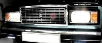
of the VAZ 2107
. But on reflection.
— Next, the prepared layout must be transferred to any material. It can be plastic, wood or other available material. Cut out the frame according to the layout.
— It is also recommended to decorate the finished frame with any material to create an attractive appearance. For example, it could be genuine leather or a substitute of the desired color.
— When the frame is ready, you can insert a new radio into it.
— You also need to take care of places to mount the radio. If they are not there, then you can use a drill to make holes for fastening in the right places.
- In addition, it is recommended to prepare self-tapping screws or screws for fastening.
Car sound system
Rarely does a driver go without music in the cabin. Depending on the owner's preferences, the system can be simple or complex. Advanced speakers. This is a separate topic, worthy of a multi-letter story with a continuation. The degree of sophistication of acoustics is limited only by the wallet of a car audiophile and his personal understanding of cool. In this article we will talk about what it is and how to install the simplest music in the VAZ interior.
Any acoustic system, including a car one, consists of a main acoustic system (MA) and speakers. In the simplest case, these functions are performed by a radio tape recorder and a pair of speakers. By default, a modern tape recorder combines a music player from digital disk media or flash drives and a radio. There is also a built-in amplifier.
The original location of the radio, as provided by the manufacturer, is on the panel above the interior fan switch. Before first use, the mounting hole is closed with a plastic plug.
Conclusion
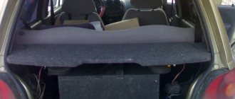
If you're planning a standard two-front, two-rear speaker setup, the front pairs of front doors are the best location. The rear ones are mounted on a shelf, for which it is better to make a special podium. The wires for the front pair are stretched under the panel, and for the rear pair near the handbrake. under the seat. Route the wiring so that the cables do not accidentally touch or become pinched during operation.
The external antenna is usually located on the windshield. The black wire of the antenna is connected to ground, the other wire. to the corresponding radio output.
These brief recommendations will allow you to connect a radio to a VAZ car. For more information about the construction process, see
Starting the installation process
How to connect a car radio to a VAZ 2106
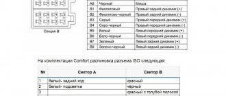
First of all, you should check the power supply wires, each of which should have its purpose written on it. The wire can simply be painted in a certain color:
- The red color of the wire will indicate the cable that provides power plus 12 V when the ignition is on.
- Yellow will indicate constant power.
- Blue power cord to antenna.
- The orange wire is for controlling the backlight.
- The black wire is always negative.
Let's consider installing the main unit, which, in addition to playing CDs, is also equipped with a radio:
- We study the speaker connection unit (see How to choose speakers for a car radio). It consists of 8 plugs. Each speaker has two plugs. This results in 4 columns x 2 = 8.
The note. The speakers can be installed as follows: two in the front door, two in the rear parcel shelf.
- We study the player's power supply, which consists of 5 plugs.
The note. This doesn't mean it always has to be this way. There are different power supplies, and they may have different numbers of plugs: 5, 8, etc.
READ Turn Signal Relay VAZ 2106 5 Contacts Connection
How to install a car radio on a VAZ 2107
The speaker and power supply are traditional. In other words, there is a predetermined purpose for them (the caps). In our case, it is assumed that these pads are included in the car kit and do not need to be purchased separately:
- We buy special connectors, which are very important when connecting a car radio. Such components a priori eliminate the need for soldering. These components are designed to connect an additional wire to the vehicle wiring. Typically the connector has two channels: the main wire goes into the through hole, and the additional wire goes into the curtain.
The note. In the contact part of the connector there are two holes for clamping conductors through which current flows.
- As for the place of insertion into the standard wiring, you can find it using the connection diagram.
- After the connector is integrated into the vehicle's wiring, it is necessary to check the voltage plus 12 V and ground. This is done on the corresponding pins of the block. We use a simple probe. a 12 V car light bulb with two wires connected or a special one.
- We connect the gaskets for the amplifier (which were not used or will not be used during installation) with electrical tape.
The note. Wiring harness. This is a kind of block, it should come out so that the wires for connecting the player are pulled out without excessive tension.
- Now you need to pass the wire harness for the turntable and antenna through the special slide of the main unit.
- We insert the curtain into the console connector on the instrument panel.
Advice. The slide must be installed without distortion. Therefore, the outer flange of the slide must be close to the edges of the turntable seat.
- Take a suitable screwdriver and bend the mounting tab of the mustache. We make sure that they sit securely in the nest and do not wobble.
How to connect a car radio to a VAZ 2101
- While we are in no hurry to install the car radio, we will once again check the voltage and ground with a homemade probe on the necessary contacts of the power supply.
- Connect the antenna cable to the radio.
- Also connect the remaining wires.
- We insert the radio into the socket on the instrument panel.
Connection diagram for car radio VAZ 2105
The note. To easily remove the radio from the slide, the installation kit includes two pullers. They are installed on both sides in the gaps that remain between the player’s walls and the sled. You just need to pull out these pullers to remove the radio.
- We install the car radio panel trim.
- We install the panel itself.
- We check the operation of the entire system.
Connection diagram for car radio on VAZ 2105
Advice. It is recommended to protect radio communication points with insulation. You can use colored tape.
At this point, the operation of installing the radio with your own hands can be considered complete. It won't hurt to use other step-by-step instructions. It is also important to review photos and materials during the process. The price of self-installation will a priori please everyone, because for comparison it will be several times lower than what you will have to pay to specialists.
How to install
When choosing a radio, it is recommended to pay attention to products manufactured under the Pioneer brand. It is characterized by high performance characteristics and can last for a long period. You can install the radio to improve the quality of music as follows:
- In the car, the radio is fixed using a standard ISO connector. This international standard has become widespread.
- When choosing a radio, you should consider its size. If they do not fit, installation will become more difficult. The seat can be changed in the machine.
- There are no problems with updating the radio if the seat has the required dimensions. All cables are fixed into a rectangular block.
- If the contacts do not fit, you can use a special adapter.
How to properly connect a radio to a VAZ 2106
Group: Zhigulists Messages: 391 Registration: 30.3.2007 From: Perth, Western Australia User No.: 26 Car: Ford Falcon BA 4.0L 6Cyl, Automatic Colour: White Year of Manufacture: 2003 Thanks said: 2 times
Because, if we say a meter (two or three) of this wire going to the radio will get pinched and frayed and end up on ground (body) without a fuse at the beginning of this wire
(where it is connected to +12) there will be a fire!
Group: Zhigulyonok Messages: 13 Registration: 1.4.2007 From: Orenburg User No.: 38 Car: VAZ 21063 Color: SAFARI Year of Issue: 1996 Thanks said: 0 times
Logbook VAZ 21074 (2006)
Hi all! Last fall, one unpleasant incident occurred - in a hurry, I forgot to turn off the radio panel, leaving it in the AUX IN position, since I usually use it instead of a pause. The radio is an old Alpine with a DVD drive.
At that time, there was still an old battery that did not hold a charge well and required regular recharging; as a result, in the evening the starter was unable to crank the engine, so I had to “light it.” After this incident, I decided to check the current leakage and the radio connection itself, since it had already been received with the car.
In the same position of the socket on the alarm, the leakage current was as much as 0.7 A, which is an order of magnitude greater than the permissible values - they write differently everywhere, but if we take the largest range, then the permissible leakage current is only 0.015-0.070 A or 15-70 mA .
I decided to remove the radio and look at the connection - as expected, the red and yellow power wires are twisted together and through the green they go to the battery, also, the ground wire goes through the twist to the negative terminal, it turns out that the chip was simply cut off and all the wires are connected with twists. Apparently, this is also why, when starting the car, the radio constantly turned off for 1-2 seconds.
I found a factory wiring diagram for the Alpine radio, which, in principle, applies to all others.
The yellow wire, as I understand it, is responsible for memory, settings and general power, and is connected directly to the battery. And the red one is responsible for managing this power, that is, for turning on the panel, and it is connected from the ignition, that is, not directly. Apparently, in order not to bother, the previous owner simply twisted them together.
I decided to check how much actually “leaks” through just one radio. I connected the multimeter to the twist gap of the yellow and red wires to the battery:
1. With the socket removed - practically no consumption.
2. With it inserted, but not turned on - already an order of magnitude higher than normal.
3. In the mode in which the panel was left, even more came out. Thus, in the 10 hours that the car was parked, up to 5-7 A could be drained from the battery, which was no longer enough to start.
4. With the radio turned off via the button - within normal limits, but still a bit much.
Now we turn off the red one and leave only the yellow one, as it should be when the ignition is turned off - the radio now does not turn on and the leakage is minimal.
Therefore, I decided to run the red wire according to the factory circuit and protect myself from repeating this situation with discharge, especially since it would not be very good for a new battery.
At first, I thought about connecting to the free INT output on the ignition switch, but it turns out that it has a constant + there, but there is no ACC mode, like on foreign cars.
I didn’t want to cut the adjacent wire on which the variable + appears, much less disassemble and modify the contact group. Therefore, after rummaging on the Internet, I found out that the mounting block has free contacts that can be connected to and they are already protected by fuses.
At first I wanted to connect to plug Ш13-6 from the passenger compartment, but it was already occupied, so I had to route the red wire through the engine panel and connect to plug Ш10-8.
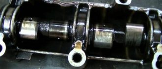
The second plug on the left is black when looking at the block, although for some reason it appears under brown in some diagrams. I soldered a “mother” terminal with a tendril to the wire so that it would stay in the chip.
The remaining contacts were also soldered and insulated with heat shrink.
There was no need to pull the yellow and black ones, since the cross-section of the ones already standing was sufficient; it is recommended to install the power and mass sections with a cross-section of 2.5-4 mm.
I ran the yellow (green) wire from the battery through a 10 A fuse, temporarily wrapped it with electrical tape, while special chips for the fuses are coming from China. It turns out that now both power wires are protected, not counting the fuse in the radio itself. Also, I replaced and soldered the round terminals to the battery.
I assembled everything in place, hooked up a multimeter to the battery - the total leakage is only 0.02 A, with or without the socket inserted. And the radio stopped turning off when starting the car.
However, with this connection there is a small drawback - in order to listen to music, you must turn on the ignition, which on top of everything else results in quite a lot of consumption on the injector. It was possible, of course, to simply put a button in the gap of the red wire, but, after all, you could forget to turn it off. So, I left it like that for now, maybe I’ll come up with something later.
Let's do the math:
Wire 1m - 30r
Clamps, heat shrink - 20 rub.
Fuse 10A - 10p
Total - 60 rub.
Subscribe! Good luck on the roads!