Heating VAZ 2110, design and principle of operation of the stove
The heating system of a VAZ 2110 car consists of: an electronic control unit for the heater, operating from the passenger compartment, air ducts that extend from the stove, and a heater unit that provides heating for the interior.
The heater unit is represented by the following elements:
- An electric motor on which a fan is attached to pump hot air.
- A radiator, without which the system will not work. At the same time, unlike the old-style heater, the radiator of the new VAZ 2110 stove does not have a tap that shuts off the flow of antifreeze (antifreeze) through the radiator. As a result of this, it is always (whether in summer or winter) heated. This was done to eliminate leaks, which are often observed through this faucet, and also to heat the interior as quickly as possible, if necessary. In the summer, fresh air ventilation goes past the radiator, but some VAZ 2110 car owners add this valve to the system when repairing the stove.
- Three dampers, one of which closes/opens the heater duct, the second is responsible for air intake recirculation, and the third, most important for the interior, controls the heater.
- A resistor that regulates the blowing speed.
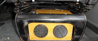
All elements are contained in a block with additional fittings, shields and valves. This entire unit is dressed in a housing and located in the engine compartment closer to the dashboard.
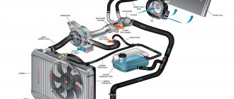
Operating principle and design of the VAZ-2110 stove
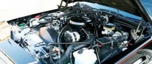
The VAZ-2110 heater includes many different components. Under the hood of the car is the main operating element - the radiator. It is thanks to the radiator that warm air enters the car interior through a special distributor with pipes. In most cases, the heated air flow is directed to blow on the windshield, so the stove is also considered one of the key elements of safe driving in the winter.
It is possible to control the operation of the interior heater thanks to the SAUO unit. This unit works in conjunction with a cabin temperature sensor. Both devices depend on each other, since it is the sensor that sends the temperature to the unit, after which the received indicators are compared with the conditions set on the handle. Using the control lever, you can set intermediate and two extreme positions - MIN and MAX. If the lever is placed in the extreme position, the heater will operate without using a temperature sensor.
Another very important component of the stove is a special drive that drives the dampers. It is this device that is responsible for opening and closing them. Failure of the drive most often leads to the stove starting to blow cold. If the dampers were in the closed position and the drive stopped performing its direct duties, then the heater will not function at all.
Speaking about the design of any car heater, it is worth highlighting, first of all, the following components:
- Radiator – helps heat the air;
- Distributor – supplies warm air into the cabin through pipes;
- SAUO block – heater operation control unit;
- Heating system control lever;
- Dampers – allow you to regulate the air temperature;
- Drive – drives the dampers.
The stove on the “ten” works on the principle of recirculation. This means that all the air involved in the circulation is not taken from the street, it is constantly located inside the heating system of the VAZ-2110. The obvious advantage of this operating principle is that large amounts of dirt, dust and other impurities that quickly clog the filters do not come in from the street. But such a system is not without its drawbacks. When the VAZ-2110 interior heating system is operating, the windows fog up heavily.
Air ducts VAZ 2110, structure and why they are needed
Air ducts provide:
- Interior ventilation through central nozzles.
- The air distributor is responsible for supplying heat or regular air for the purpose of ventilation.
- There is a whole system for heating the feet, which consists of five nozzles.
- Two air ducts are directed to the rear of the car interior.
- Two side air ducts are responsible for heating the side windows, as well as part of the interior, which provides better heating.
- There are also 2 nozzles for ventilation.
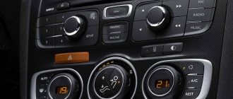
Furnace electronic control unit
The electronic control unit includes:
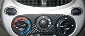
- Controller handle. This device makes it possible to set the temperature in the cabin, which is produced by the stove unit. The controller handle sets the air temperature, which corresponds to that outside, and is turned on by turning the handle (up to 30 degrees Celsius). This part is usually called the ACS controller.
- The temperature sensor controls the activation of the heater when the air temperature in the cabin decreases by 2 degrees against the set one. The sensor has a microfan, and when the control knob is located in position A, a micromotor in the stove block turns on, after which the damper begins to operate, which ensures proper heating. Therefore, before repairing the heating system, you need to check the operation of this sensor. It is located near the heating lamp on the ceiling. Since its repair is not provided, if it breaks, this device must be replaced immediately.
Stove fan.
Stove 2110, how the new stove differs from the old stove
- The main difference between the new stove and the old-style stove is in the design of the radiator. Therefore, if, when repairing the heating system, you decide to install a new radiator, you should take into account some nuances.
- In addition, the ACS controller also has certain differences. Thus, 4 and 5 position controllers produced before the fall of 2003 have already been discontinued and they are not suitable for new heater models.
- Micro gearboxes manufactured before September 2003 also differ. The main difference is the resistors, so you need to pay attention to whether the resistor in the MMR model you purchased is interchangeable.
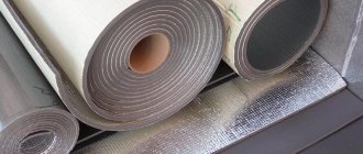
Heater resistor
Diagram and design of the heating system in the VAZ-2110
The heating unit itself is represented by several components:
- Electric motor. A ventilation device is fixed on it, designed to pump a hot air flow.
- A radiator device, the failure of which will lead to the inoperability of the stove. On old-style heating systems, the radiator assembly is not equipped with a valve designed to shut off the flow of coolant through the device. Therefore, the unit practically does not leak, since leaks are usually associated with the faucet. The absence of this element ensures the fastest heating of the car interior.
- Three dampers. One of them is designed to close and open the heating channel, the second is used for recirculation, and the third is necessary to control the heater.
- The resistor device is designed to regulate the blowing speed.
Components of the heating system
Main parts of the heating system for the interior of a VAZ 2110 car:
- 1 - electro-pneumatic valve device;
- 2 — front housing of the air intake of the heating unit;
- 3 - water deflector device, presented in the form of an air intake flap;
- 4 — valve device for controlling the damper of the air flow recirculation system;
- 5 — recirculation system damper;
- 6 — rear part of the air intake housing of the heating unit;
- 7 — heating channel damper;
- 8 — damper of the heating unit control system;
- 9 — radiator unit;
- 10 - protective plastic casing of the radiator device;
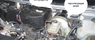
- 11 - bushing installed in the steam outlet pipe;
- 12 — bushing for the supply line of the heating unit;
- 13 — bushing of the outlet pipe;
- 14 - electric motor of the heating system;
- 15 — electric motor housing;
- 16 - supporting surface of the damper drive lever used to control the stove;
- 17 — drive handle for controlling the damper of the heating system;
- 18 — gear motor of the drive device, presented in small sizes;
- 19 - resistor element;
- 20 - protective cover for the heating unit lining.
Connection diagram for blowers and controls
Main components of the stove:
- 1 - air ducts designed to warm up the rear of the car;
- 2 — plastic lining running from the center console to the rear seats;
- 3 - blowers designed to blow feet;
- 4 - main nozzles for ventilation of the car interior;
- 5 — side nozzles for interior ventilation;
- 6 — nozzles intended for heating the glass installed in the front doors;
- 7 — control knob for the interior heating unit;
- 8 — plastic housing of the air distribution device;
- 9 — damper for the foot warming system;
- 10 - plastic flap designed to warm up the windshield;
- 11 - heating unit.
The difference between old and new stoves
Old and new type heating systems have some features in connection diagrams as a result of the following differences:
- Radiator design. Heats in cars of different years of manufacture have different radiator assembly designs. In older heating systems, radiators are equipped with taps to drain the refrigerant.
- Different designs of SAUO controllers. Cars manufactured before 2003 used five position controllers. In newer versions of the car, devices numbered 4 and 5 were removed from the design.
- Micro-gearbox design. The main difference is the different type of resistor elements. When replacing elements, you need to consider whether these parts are interchangeable or not.
Causes of furnace malfunction
- The oven temperature is not regulated. The reason must be sought in the control unit or in the damper.
- The ceiling sensor does not work.
- The heater does not work, only cold air enters the cabin.
- Hot air does not flow well to the side windows and/or to the feet.
- The coolant level drops, which can happen either obviously (when it flows from the pipes or radiator) or covertly.
- The stove works, but is very noisy.
Tuning the VAZ 2110 stove
Hello! The post is not mine, posted at the request of one of the visitors! I’m ready to share the results of the experiment conducted on my car)))
The other day
I upgraded my stove . Before that, I carefully read on the forums who does what and finally decided to do a little work on the cooling system according to the recommendations in one of the articles.
Now about the main thing, as we all know, the hole in the bypass channel is 11 mm and it is from it that heat comes into the cabin, our task is to reduce it by 5 mm. As a result, we get increased circulation of coolant in the heater radiator and, as a result, an increase in temperature. We were lucky with the weather: it was sunny and -10 degrees, I went to my garage. On the way, I stopped at a car shop and bought an F16 hose and several clamps. It’s probably very simple to talk in detail about how the antifreeze is drained. After the antifreeze was drained, a problem arose - the hoses and the thermostat “stuck” to each other. It took a long time to separate them and spent a lot of time, but the result was worth it - the hoses were disconnected and at the same time remained completely intact. Next, I attached a hose from the expansion tank to the outlet of the heater radiator and had to shorten it by about 4-5 cm. The hose seemed to be in order. Removing the thermostat was easy; you just need to unscrew the 2 nuts that are secured with studs. The thermostat was immediately thoroughly cleaned, washed and divided in two (preferably with a hexagon). Now the next step is to make the plate. First, I cut out a paper model - the size was correct. Then, on an iron sheet (an old radio tape recorder was useful for the material), I marked the contour of the future part. Scissors for cutting iron and then it is better to process the edges using a file. Next you need to drill holes, having previously marked them on the plate. Finally, I got to work on the thermostat housing, drilled holes there too (better take a longer drill) and screwed everything in with self-tapping screws. Now about what happened: the size of the bypass channel was 1.1 cm, made it 0.6 cm. I assembled the thermostat using sealant and there is quite a bit of work left. A hose (about 35 centimeters) needs to be screwed to the heater radiator; the thermostat also needs to be screwed there where the expansion tank hose was. Assembly is the same as disassembly, only in reverse order. This is clear to everyone, I won’t describe it in detail. That seems to be all. Time to check the result of the work, I turn the ignition key and the BC lights up - cool temperature. liquids -1. I start the car, after five minutes it shows 46, most likely the liquid has not yet been distributed throughout the system. This is clear. I turn the stove on to second speed with maximum temperature, warm air is already coming out. I inspected the car, looked under the hood - nothing was leaking. Everything was fine. A couple more minutes pass and it already displays 60 degrees. As a result, about twenty minutes have passed, the temperature has risen to 85, but it doesn’t rise any further, I waited some more, collected the tool, I think it’s idling, I need to take it for a ride. I drove around the city for two hours or even more, it stays stable at about 90. The stove really started to warm up, if anyone has problems with the onset of cold weather, I advise you to try it. I hope that everything described in detail above will help someone as much as it did me)
Thanks for subscribing!
If the temperature is not regulated, reasons and how to fix it
If you cannot adjust the temperature of the air that enters the cabin, the fault may lie in the temperature sensor located on the ceiling, near the ceiling light. To check it, turn the control all the way to the right, then bring your hands to the air flow that comes from the heating system. If heat flows no matter what position the regulator is in (in the red part), then the problem is not with the sensor. But, if air flows only when the regulator is located in the maximum heating position, it must be replaced (or the regulator itself needs to be replaced).
Gearmotor
You also need to check the condition of the damper. You get to it through the engine compartment - you need to remove the central deflectors and move the flap by hand. If you have to remove it, it is better to replace the plastic one, which comes standard, with an aluminum one, since it does not freeze and deform so quickly.
VAZ 2110, stove device
The car has a flow-exhaust ventilation and heating system, and all the air enters the cabin through the windshield lining, either under natural pressure while the car is moving, or forcefully, under the action of a heater supercharger. The inlets are equipped with valves that prevent warm air from escaping from the passenger compartment. The air flow is formed so that it can exit between the cracks in the panel onto the windshield, into the deflectors at the ends of the doors and through the ventilation holes in the driver's and passenger's feet.
The air that enters the cabin can be heated by passing through the heater radiator if the air duct damper is placed in a certain position. Warm air is also supplied to the windshield, to the front side windows through the deflectors, at two points to the driver's and front passenger's feet and to the rear of the cabin through the trim on the tunnel and through the air duct under the front seats. The stove can operate in air recirculation mode, but only if the engine is turned on.
The gearmotor is faulty, how to replace the gearmotor, step-by-step instructions
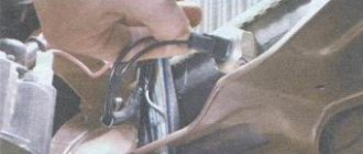
- We dismantle the wipers.
- We remove the frill.
- Using a short Phillips screwdriver, unscrew the three screws that secure the gearbox.
- Unfasten the wires.
- We install a new gear motor in place of the old one, for which you should ask an assistant to switch the positions of the regulator while you are installing this part.
- We install the frill and wipers back.