Here I found useful information on typical parameters. Made essentially as a note to myself.
For many novice diagnosticians and ordinary car enthusiasts who are interested in the topic of diagnostics, information about typical engine parameters will be useful. Since VAZ car engines are the most common and easiest to repair, we’ll start with them. What should you pay attention to first when analyzing engine operating parameters? 1. The engine is stopped. 1.1 Coolant and air temperature sensors (if equipped). The temperature is checked to ensure that the readings correspond to the actual engine and air temperatures. It is better to check using a non-contact thermometer. By the way, one of the most reliable in the injection system of VAZ engines are temperature sensors.
1.2 Throttle position (except for systems with an electronic gas pedal). The gas pedal is released - 0%, the accelerator is pressed - according to the opening of the throttle valve. We played with the gas pedal, released it - it should also remain 0%, while the ADC with a dpdz of about 0.5V. If the opening angle jumps from 0 to 1-2%, then as a rule this is a sign of a worn out valve. Less common are faults in the sensor wiring. With the gas pedal fully pressed, some units will show 100% opening (such as January 5.1, January 7.2), while others such as Bosch MP 7.0 will show only 75%. This is fine.
1.3 MAF ADC channel in rest mode: 0.996/1.016 V - normal, up to 1.035 V is still acceptable, everything above is already a reason to think about replacing the mass air flow sensor. Injection systems equipped with feedback from an oxygen sensor are able to correct, to some extent, incorrect readings of the mass air flow sensor, but there is a limit to everything, so you should not delay replacing this sensor if it is already worn out.
2. The engine is idling.
2.1 Idle speed. Typically this is 800 - 850 rpm with a fully warmed up engine. The idle speed value depends on the engine temperature and is set in the engine control program.
2.2 Mass air flow. For 8-valve engines, the typical value is 8-10 kg/h, for 16-valve engines - 7-9.5 kg/h with a fully warmed-up engine at idle. For the M73 ECU these values are slightly higher due to a design feature.
2.3 Length of injection time. For phased injection, the typical value is 3.3 - 4.1 ms. For simultaneous – 2.1 – 2.4 ms. Actually, the injection time itself is not as important as its correction.
2.4 Injection time correction factor. Depends on many factors. This is a topic for a separate article, but it’s worth mentioning here that the closer to 1,000 the better. More than 1,000 means the mixture is further enriched, less than 1,000 means it is leaner.
2.5 Multiplicative and additive components of self-learning correction. A typical multiplicative value is 1 +/-0.2. The additive is measured as a percentage and should be no more than +/- 5% on a working system.
2.6 If there is a sign of engine operation in the adjustment zone, based on the signal from the oxygen sensor, the latter should draw a beautiful sinusoid from 0.1 to 0.8 V.
2.7 Cyclic filling and load factor. For “January” typical cyclic air consumption: 8 valve engine 90 - 100 mg/stroke, 16 valve engine 75 -90 mg/stroke. For Bosch 7.9.7 control units the typical load factor is 18 – 24%.
Now let's take a closer look at how these parameters behave in practice. Since I use the SMS Diagnostics program for diagnostics (hi to Alexey Mikheenkov and Sergey Sapelin!), all the screenshots will be from there. The parameters were taken from practically serviceable cars, with the exception of specially stated cases.
VAZ 2110 8-valve engine, control unit January 5.1 Here, the CO correction coefficient has been slightly adjusted due to slight wear of the mass air flow sensor.
VAZ 2107, control unit January 5.1.3
VAZ 2115 8 valve engine, control unit January 7.2
Engine VAZ 21124, control unit January 7.2
VAZ 2114 8 valve engine, Bosch control unit 7.9.7
Priora, VAZ 21126 1.6 l engine, Bosch control unit 7.9.7
Zhiguli VAZ 2107, control unit M73
Engine VAZ 21124, control unit M73
VAZ 2114 8 valve engine, M73 control unit
Kalina, 8 valve engine, M74 control unit
Niva VAZ-21214 engine, Bosch ME17.9.7 control unit
And in conclusion, let me remind you that the above screenshots were taken from real cars, but unfortunately the recorded parameters are not ideal. Although I tried to record parameters only from serviceable cars.
Optimal operation of a car engine depends on many parameters and devices. To ensure normal operation, VAZ engines are equipped with various sensors designed to perform different functions. What you need to know about diagnosing and replacing controllers and what are the parameters of sensors for VAZ injection engines is presented in the table in this article.
Features, diagnostics and replacement of elements of injection systems on VAZ cars
Below we will look at the main controllers!
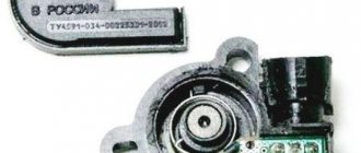
Hall
There are several options for how you can check the Hall sensor of a VAZ:
- Use a known working device for diagnostics and install it instead of the standard one. If after replacement the problems in engine operation cease, this indicates a malfunction of the regulator.
- Using a tester, diagnose the controller voltage at its terminals. During normal operation of the device, the voltage should be from 0.4 to 11 volts.
The replacement procedure is performed as follows (the process is described using the example of model 2107):
- First, the switchgear is dismantled and its cover is unscrewed.
- Then the slider is dismantled; to do this, you need to pull it up a little.
- Remove the cover and unscrew the bolt that secures the plug.
- You will also need to unscrew the bolts that secure the controller plate. After this, the screws that secure the vacuum corrector are unscrewed.
- Next, the retaining ring is dismantled and the rod is removed along with the corrector itself.
- To disconnect the wires, you will need to move the clamps apart.
- The support plate is pulled out, after which several bolts are unscrewed and the manufacturer dismantles the controller. A new controller is being installed, assembly is carried out in the reverse order (the author of the video is Andrey Gryaznov).
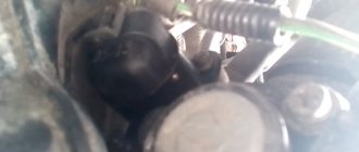
Speeds
The following symptoms may indicate a failure of this regulator:
- at idle, the speed of the power unit floats, if the driver does not press on the gas, this can lead to an arbitrary shutdown of the engine;
- the speedometer needle readings float, the device may not work as a whole;
- fuel consumption has increased;
- the power of the power unit has decreased.
The controller itself is located on the gearbox. To replace it, you only need to jack up the wheel, disconnect the power wires and remove the regulator.
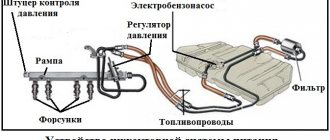
Fuel level
The VAZ or FLS fuel level sensor is used to indicate the remaining volume of gasoline in the fuel tank. Moreover, the fuel level sensor itself is installed in the same housing with the fuel pump. If it malfunctions, the readings on the dashboard may be inaccurate.
The replacement is done like this (using the example of model 2110):
- The battery is disconnected and the rear seat of the car is removed. Using a Phillips screwdriver, unscrew the bolts that secure the fuel pump hatch and remove the cover.
- After this, all wires leading to it are disconnected from the connector. It is also necessary to disconnect all the pipes that are supplied to the fuel pump.
- Then the nuts securing the clamping ring are unscrewed. If the nuts are rusty, treat them with WD-40 before unscrewing.
- Having done this, unscrew the bolts that directly secure the fuel level sensor itself. The guides are pulled out from the pump casing, and the fasteners need to be bent with a screwdriver.
- At the final stage, the cover is dismantled, after which you will be able to gain access to the FLS. The controller is replaced, the pump and other elements are assembled in the reverse order of removal.
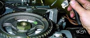
Video “Briefly about replacing the camshaft sensor on a VAZ”
You can learn more about where the VAZ camshaft sensor is located and how to replace it in a garage from the video below (the author of the video is Vitashka Ronin).
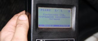
VAZ-ten, VS 5.1 (Russia-83), 8kl. When viewing the channels, the ADC found that Ubrt = 0.8v. As I understand it, an ADC (Analog-to-Digital Converter) is a chip (or several chips) in the controller that is used to convert analog signals from sensors to digital ones. And naturally, this ADC receives power from the on-board network. Tell me, is this power supplied directly from some controller leg or through its own stabilized power source in the controller? It turned out that I did not have this scheme. The car drives, the idle speed is slightly increased (about 860 - 950 rpm), the CO and CH are normal, the consumption is also low, sometimes during acceleration it seems as if someone is holding it. Arrived with the error “Low level of TPS signal.” I checked the sensor with an oscilloscope - no comments. After removal the error did not appear. MAF ADC when on. ignition=1.07v. Voltage on the “ground” of the mass flow sensor = 0.7V, when mass is applied to it, the output does not change. To clear my conscience, I replaced the TPS, MAF, IAC with serviceable ones, cleaned Dr. Pipe - the idle speed remains high, the ADC signals are the same. XX smooth. I used the F-16 scanner, the Autoas-Scan program, a USB oscilloscope and a multimeter. I'm most interested in the ADC voltage level Ubrt, how can everything work at such a low voltage? Where to look? Get into the controller? But other than blowing off the dust and checking the integrity of the tracks and parts, I can’t do anything else there. P.S. — the TPS had a seal made of microporous rubber, the print shows that it was clamped, probably because of this there was an error. Enlarged the inside with scissors. hole. Here is a picture from the ADC channel program, I hope that I have already learned how to cut a frame. Attached image (click to enlarge)
Typical operating parameters of VAZ injection engines.
For many novice diagnosticians and ordinary car enthusiasts who are interested in the topic of diagnostics, information about typical engine parameters will be useful. Since VAZ car engines are the most common and easiest to repair, we’ll start with them. What should you pay attention to first when analyzing engine operating parameters? 1. The engine is stopped. 1.1 Coolant and air temperature sensors (if equipped). The temperature is checked to ensure that the readings correspond to the actual engine and air temperatures. It is better to check using a non-contact thermometer. By the way, one of the most reliable in the injection system of VAZ engines are temperature sensors.
1.2 Throttle position (except for systems with an electronic gas pedal). The gas pedal is released - 0%, the accelerator is pressed - according to the opening of the throttle valve. We played with the gas pedal, released it - it should also remain 0%, while the ADC with a dpdz of about 0.5V. If the opening angle jumps from 0 to 1-2%, then as a rule this is a sign of a worn out valve. Less common are faults in the sensor wiring. With the gas pedal fully pressed, some units will show 100% opening (such as January 5.1, January 7.2), while others such as Bosch MP 7.0 will show only 75%. This is fine.
1.3 MAF ADC channel in rest mode: 0.996/1.016 V - normal, up to 1.035 V is still acceptable, everything above is already a reason to think about replacing the mass air flow sensor. Injection systems equipped with feedback from an oxygen sensor are able to correct, to some extent, incorrect readings of the mass air flow sensor, but there is a limit to everything, so you should not delay replacing this sensor if it is already worn out.
2. The engine is idling.
2.1 Idle speed. Typically this is 800 - 850 rpm with a fully warmed up engine. The idle speed value depends on the engine temperature and is set in the engine control program.
2.2 Mass air flow. For 8-valve engines, the typical value is 8-10 kg/h, for 16-valve engines - 7-9.5 kg/h with a fully warmed-up engine at idle. For the M73 ECU these values are slightly higher due to a design feature.
2.3 Length of injection time. For phased injection, the typical value is 3.3 - 4.1 ms. For simultaneous – 2.1 – 2.4 ms. Actually, the injection time itself is not as important as its correction.
We are doing renovations in the apartment. Helpful information
To help car owners, many different scanners have appeared on sale for self-diagnosis of modern engines. But without knowledge of the basics of how the injection system works, it is unlikely that such a device will provide significant assistance.
Before starting and during engine operation, the controller evaluates the coolant temperature and intake air temperature
. If the coolant temperature sensor gives incorrect readings, the control unit will excessively enrich or, conversely, lean the mixture, which will lead to unstable engine operation and difficulty starting. The coolant temperature value before starting is used to evaluate the operation of the thermostat based on the engine warm-up time. The serviceability of the sensors can be assessed before a cold start, when the coolant temperature is equal to the outside air temperature. The sensor readings in this case should also differ by no more than 1-2 degrees. If both sensors are turned off, the controller will take the values set in the “emergency” program. If the air temperature sensor is faulty, it will be difficult to start the engine, especially at low temperatures.
value in the on-board network
is also under the constant control of the control unit. Its value depends on the generator parameters. If the voltage is below normal, the controller increases the duration of energy accumulation in the ignition coils and the injection time.
Using a scanner you can take readings from the speed sensor
and compare them with the speedometer readings, thus assessing its performance.
At elevated idle speeds of a warm engine, the scanner checks the degree of throttle valve
. It is measured as a percentage, and varies from 0% when closed to at least 70% when fully open.
The volatile memory of the controller stores data on the voltage value on the throttle position sensor (TPS) in the closed state. If you install a different sensor, the voltage may be different, and therefore the controller will adjust the idle speed differently. To prevent such an error from occurring, you must remove the terminal from the battery before replacing the sensor.
Mass air flow sensor readings
(MAF), expressed in kg/h, are used by the controller to calculate most parameters. At the same time, the controller calculates the theoretical amount of air depending on the load. These two readings on a working engine should not differ much. Too large a difference between the mass air flow sensor data and the calculated value of the amount of air required indicates an engine malfunction.
The controller calculates and, if necessary, adjusts the ignition timing
(UOZ). Using a scanner you can check its size. If detonation occurs, the control unit will “correct” the OZ, which will be clearly visible on the scanner screen.
Engine load
The controller evaluates the size and speed of the throttle valve opening. It is measured as a percentage. For a warmed-up engine running at idle speed, the “engine load” parameter is a constant value. Therefore, it is very useful to remember this meaning. If it decreases sharply, this indicates the presence of extraneous air leaks. If the value of this parameter increases from the standard, the cause should, first of all, be sought in the mass air flow sensor. Also, this parameter may increase with increased resistance to rotation of the generator rotor or coolant pump. Modern engine control systems even take into account such parameters as altitude when calculating the load, reducing the opening time of the injectors with increasing altitude.
Checking the open time of the injectors
, remember that in modern phased injection systems the nozzle opens once every two revolutions of the crankshaft. In outdated ones, where the injectors fire simultaneously or in pairs - in parallel, injection is performed twice. In this case, the control pulse is twice as long in duration.
In engine braking mode, the fuel supply is either stopped or reduced to a minimum. You can check whether the fuel supply is turned off using a special parameter that has only two values: “yes” or “no”.
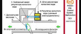
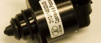
An important part of the control system is the idle speed regulator.
(RHH). But it is involved not only in idle mode, but also in other operating modes. The IAC reacts sensitively to any load changes, for example, when lighting fixtures are turned on. When checking with a scanner, the amount of movement of the IAC rod is set, while monitoring the change in engine speed.
Based on the signal level from the knock sensor
You can evaluate the noise level of the engine. It is measured in volts. In a working engine, its value ranges from 0.3 to 1 volt. In a worn engine this value will be higher.
One of the “ecological” systems of a modern car is a gasoline vapor recovery system.
. Its actuator is a solenoid valve controlled by a controller. The valve is located in the engine compartment, and clicks are heard when it operates. When checking with a scanner, the valve opening time is changed and at the same time the operation of the IAC is monitored. If it closes, then, therefore, an additional portion of purge air has entered the intake tract through the valve.
The control system settings are stored in non-volatile memory in the form of a checksum (a set of letters and numbers), and it is impossible to correct them using a scanner. This requires special software. The checksum may change if there is a failure in the controller operating program. In this case, the controller will have to be replaced, or at best, reprogrammed. The operating time of the controller is also recorded in memory, but when the battery terminal is removed, this parameter is reset to zero.
Using data on the amount of air entering the engine from the mass air flow sensor (MAF), the controller calculates the required amount of fuel and the time the injectors are open. The correctness of the calculations is checked using an oxygen sensor (lambda probe)
installed in the exhaust system in front of the catalytic converter. This process of correcting the composition of the mixture according to the readings of the oxygen sensor (OS) is called lambda regulation (or feedback).
Immediately after start-up, when the lambda probe is not warmed up to operating temperature (300°C), it does not participate in the process of regulating the composition of the working mixture, and the signal at its output is constant and equal to approximately 0.5 volts. Additional electrical heating of the sensor allows you to reduce the warm-up time. As soon as the sensor signal changes value, the controller will immediately “notice” this and include the lambda probe in the process of adjusting the mixture composition.
During operation, the DC signal constantly changes within 0.1 - 0.9 V. A high voltage level corresponds to a rich mixture, a low voltage level corresponds to a lean mixture. This is clearly visible on the scanner screen. If the screen is not large enough, you can connect the scanner to a computer monitor - the sensor signal resembles a sine wave with rectangular edges.
The controller “converts” the DC signal into an injection duration correction factor (CD). In normal condition, this parameter ranges from 0.98 to 1.02. The maximum permissible limits are from 0.85 to 1.15. Smaller values correspond to a richer mixture, larger values indicate a leaner mixture. If the coefficient is less than one, the controller reduces the injection time; if it is greater, it increases it. Values outside the specified range indicate a malfunction in the engine.
But lambda regulation alone is not enough to ensure the desired mixture composition. In modern engines, designers have taught the control unit to take into account changes in parameters - “aging” of sensors, a gradual decrease in compression in the cylinders, differences in the quality of the fuel filled and other factors. Thus, the controllers received a self-learning function. To implement it, two components were introduced - additive and multiplicative. Additive correction
(AK) self-learning “works” at idle, and
multiplicative
(MK) - in partial load mode.
AK is measured as a percentage. Its limits are from -10% to +10%. MK is a dimensionless value and can vary from 0.75 to 1.25. If any of these self-learning components approaches the limit values (in any direction), the controller will light up the “Check engine” lamp and record error PO171 or PO172 (the mixture is too lean or rich).
The meaning of self-learning correction coefficients is to maintain the injection duration coefficient (ID) close to unity (0.98-1.02). Let's look at an example. Let’s say that as a result of aging of the mass air flow sensor, the mixture becomes leaner by 15%. The controller will increase the injection duration, as a result of which the CD will increase to 1.13-1.17 (with an average value of 1.15). At this time, the adaptation mode is turned on, bringing the CD to the nominal value. The MK value is stored in the volatile memory of the controller, and during subsequent engine starts, the coefficient will regulate the mixture composition taking into account the mass air flow sensor error. AK works similarly, but in idle mode. When the malfunction is eliminated, there is no need to wait for adaptation again - just disconnect the battery so that the values of CD, AK and MK are reset to the initial ones. The second option is to use the scanner’s “reset adaptations” function.
| Parameter | Unit change | Controller type and typical values | ||||
| January4 | January 4.1 | M1.5.4 | M1.5.4N | MP7.0 | ||
| UACC | IN | 13 — 14,6 | 13 — 14,6 | 13 — 14,6 | 13 — 14,6 | 13 — 14,6 |
| TWAT | hail WITH | 90 — 104 | 90 — 104 | 90 — 104 | 90 — 104 | 90 — 104 |
| THR | % | 0 | 0 | 0 | 0 | 0 |
| FREQ | rpm | 840 — 880 | 750 — 850 | 840 — 880 | 760 — 840 | 760 — 840 |
| INJ | msec | 2 — 2,8 | 1 — 1,4 | 1,9 — 2,3 | 2 — 3 | 1,4 — 2,2 |
| RCOD | 0,1 — 2 | 0,1 — 2 | +/- 0,24 | |||
| AIR | kg/hour | 7 — 8 | 7 — 8 | 9,4 — 9,9 | 7,5 — 9,5 | 6,5 — 11,5 |
| UOZ | gr. P.K.V | 13 — 17 | 13 — 17 | 13 — 20 | 10 — 20 | 8 — 15 |
| FSM | step | 25 — 35 | 25 — 35 | 32 — 50 | 30 — 50 | 20 — 55 |
| QT | l/hour | 0,5 — 0,6 | 0,5 — 0,6 | 0,6 — 0,9 | 0,7 — 1 | |
| ALAM1 | IN | 0,05 — 0,9 | 0,05 — 0,9 | |||
| Parameter | Unit change | Motor type and typical values | ||||
| ZMZ - 4062 | ZMZ - 4063 | ZMZ - 409 | UMZ - 4213 | UMZ - 4216 | ||
| UACC | 13 — 14,6 | 13 — 14,6 | 13 — 14,6 | 13 — 14,6 | 13 — 14,6 | |
| TWAT | 80 — 95 | 80 — 95 | 80 — 95 | 75 — 95 | 75 — 95 | |
| THR | 0 — 1 | 0 — 1 | 0 — 1 | 0 — 1 | ||
| FREQ | 750 -850 | 750 — 850 | 750 — 850 | 700 — 750 | 700 — 750 | |
| INJ | 3,7 — 4,4 | 4,4 — 5,2 | 4,6 — 5,4 | 4,6 — 5,4 | ||
| RCOD | +/- 0,05 | +/- 0,05 | +/- 0,05 | +/- 0,05 | ||
| AIR | 13 — 15 | 14 — 18 | 13 — 17,5 | 13 — 17,5 | ||
| UOZ | 11 — 17 | 13 — 16 | 8 — 12 | 12 — 16 | 12 — 16 | |
| UOZOC | +/- 5 | +/- 5 | +/- 5 | +/- 5 | +/- 5 | |
| FCM | 23 — 36 | 22 — 34 | 28 — 36 | 28 — 36 | ||
| PABS | 440 — 480 | |||||
The engine must be warmed up to the TWAT temperature indicated in the table.
| Idle mode (all consumers are turned off) | ||
| Crankshaft rotation speed rpm | 840 — 850 | |
| Zhel. speed XX rpm | 850 | |
| Injection time, ms | 2,1 — 2,2 | |
| UOZ gr.pkv. | 9,8 — 10,5 — 12,1 | |
| 11,5 — 12,1 | ||
| IAC position, step | 43 | |
| Integral component of pos. stepper motor, step | 127 | |
| Correction of injection time according to DC | 127-130 | |
| ADC channels | DTOZH | 0.449 V/93.8 deg. WITH |
| Mass air flow sensor | 1.484 V/11.5 kg/h | |
| TPDZ | 0.508 V /0% | |
| D 02 | 0.124 - 0.708 V | |
| D children | 0.098 - 0.235 V | |
| 3000 rpm mode. | ||
| Mass air flow kg/hour. | 32,5 | |
| TPDZ | 5,1% | |
| Injection time, ms | 1,5 | |
| IAC position, step | 66 | |
| U Mass air flow sensor | 1,91 | |
| UOZ gr.pkv. | 32,3 | |
| Idle speed | 770-870 |
| Fuel pressure | 2.8 - 3.2 atm. |
| Minimum pressure developed by the fuel pump | 3 atm. |
| Injector winding resistance | 14 - 15 ohm |
| TPS resistance (terminals A and B) | 4 kOhm |
| Voltage between terminal B of the air pressure sensor and ground | 0.2 - 5.0 V (various modes) |
| Voltage at terminal C of the air pressure sensor | 5.0 V |
| Air temperature sensor resistance | at 0 degrees C - 7.5/12 kOhm |
| at 20 degrees C - 3.1/4.0 kOhm | |
| at 40 degrees C - 1.3/1.6 kOhm | |
| IAC valve coil resistance | 8.5 - 10.5 Ohm |
| Resistance of ignition coil windings, terminals 1 - 3 | 1.0 ohm |
| Short circuit secondary winding resistance | 8 - 10 kOhm |
| DTOZh resistance | 20 degrees C - 3.1/4.1 kOhm |
| 90 degrees C - 210/270 Ohm | |
| HF Sensor Resistance | 150 - 250 Ohm |
Readings were taken with a 5-component gas analyzer only from 1.5-liter engines. In principle, each engine had different readings, so only the readings of those cars that had 14.7 ALF on the gas analyzer at 1% CO were taken into account. Even for such machines, the readings vary slightly, so we had to average some data.
| A.L.F. | CO% | A.L.F. | CO% | A.L.F. | CO% | A.L.F. | CO% |
| 17,00 | 0,1 | 14,93 | 0,8 | 14,12 | 2,0 | 13,58 | 3,4 |
| 16,18 | 0,2 | 14,81 | 0,9 | 14,03 | 2,2 | 13,41 | 3,6 |
| 15,83 | 0,3 | 14,7 | 1,0 | 13,94 | 2,4 | 13,22 | 3,8 |
| 15,58 | 0,4 | 14,57 | 1,2 | 13,87 | 2,6 | 13,05 | 4,0 |
| 15,38 | 0,5 | 14,42 | 1,4 | 13,80 | 2,8 | 12,80 | 4,6 |
| 15,20 | 0,6 | 14,30 | 1,6 | 13,72 | 3,0 | Measurements (c) WIND | |
| 15,05 | 0,7 | 14,20 | 1,8 | 13,65 | 3,2 | ||
Currently, it is common practice to rush to seek help from specialists of various levels at the slightest malfunction that occurs on cars with injection engines, who often offer to get rid of the problem using an untested tuning method. Meanwhile, such a solution often only brings harm, and if you have a certain amount of knowledge, you can determine the cause of the injector failure independently and with minimal losses.
Lighting up and other risky actions with food are very dangerous for injectors. If this situation fails, you must completely disconnect the terminals from your battery - in this case the danger is minimal.
It is not recommended to disconnect the main ground wire unless absolutely necessary - such an action can lead to erasing the ECM adaptation information. If you have to make a shutdown, you need to try to ensure that it takes no more than a minute. When reconnecting the ground, let the engine idle for about three minutes.
A charging starting device of unknown origin can damage the ECM due to excessive starting voltage surges.
If the vehicle's power plant is equipped with a neutralizer, when starting by towing, fuel may enter the catalyst, ignite in it and, accordingly, damage the neutralizer.
The presence of a lambda probe places increased demands on the quality of gasoline (excessively leaded fuel leads to over-enrichment of the mixture, ECM failures, engine overheating, etc.).
The starter turns over, but the engine does not start
We check the condition and functionality of the crankshaft sensor, for which, first of all, we visually assess the integrity of the shielding braid and wire. The internal resistance of the sensor should be between 600 and 1000 Ohms. The distance between it and the toothed synchronization disk should not exceed 1.5 mm.
We check the fuel pump by the sound of its operation. If there is no sound, then to check the circuits we apply 12V to it directly. When the pump is turned on, pressure should be felt in the rubber tubes, and when it is turned off, the pressure should not drop too quickly. The smell of gasoline may indicate a failure of the pressure regulator.
When checking the spark, we ensure reliable contact of the spark plugs with the ground (otherwise we risk burning the ECM). We also measure the presence of input voltage at the coil terminals, as well as the resistance of the secondary winding (4-6 Kom).
When checking the power supply network, the voltage with the engine running should be about 14 V (at least 8 V when the starter is running).
Don't forget to just reconnect the ECM connectors.
We try to start the engine with the gas pedal slightly pressed. If the engine starts, then the problem lies in the RDV or one of the sensors is faulty (most often the coolant sensor). If the engine stalls when you release the pedal, check the adjustment of the XX regulator cable.
Using a special probe, we evaluate the control of the injectors. When controlled by a tester, the resistance of serviceable injectors is 12-20 Ohms.
Alternatively, you can experiment with disconnecting the maximum number of sensors (with the exception of the synchronization sensor) and try to start the engine with various combinations.
The engine is difficult to start
We check the ignition circuits and, first of all, the high-voltage part (the condition of the spark plugs, high-voltage wires, the absence of carbon deposits, cracks, etc.).
We check the readings of the coolant sensor (TWAT parameter) - the deviation should not exceed 5-6°C.
We check the readings of the throttle position sensor (THR parameter) - as you press the gas pedal, the readings should change from 0% to 95-100%.
We check the air temperature sensor (TAIR parameter).
Dips, jerks, low throttle response
Again, check the condition of the injectors. In particular, at 2500 rpm we turn off the injectors one at a time and measure the drop in rpm - if when one of the cylinders is turned off the rpm drop is too different, then perhaps the reason is in this injector.
It wouldn't hurt to evaluate the ignition timing setting.
In the event of a sudden change in speed without your intervention, it is necessary to check the shielding of the wires going to the phase and HF synchronization sensors.
Excessive fuel consumption
Possible reasons:
- It's time to change the spark plugs;
- The injectors are stuck;
- Coolant sensors and mass air flow sensors are capricious;
- The phase sensor (if equipped) is faulty.
Unstable idle
We check the air leakage bypassing the mass air flow sensor and, of course, the mass air flow sensor itself.
Checking the L-probe. It may be necessary to adjust the composition of the mixture using the CO potentiometer.
Checking the coolant temperature sensor.
We check the throttle position sensor at zero position.
We carry out a full range of ignition testing.
January 4; January 5.1,VS 5.1,Bosch 1.5.4; Bosch MP 7.0; January 7.2,Bosch 7.9.7
table of tightening torques for threaded connections
January 4
| Parameter | Name | Unit or condition | Ignition on | Idling |
| COEFFF | Fuel correction factor | 0,9-1 | 1-1,1 | |
| EFREQ | Frequency mismatch for idle speed | rpm | ±30 | |
| FAZ | Fuel injection phase | deg. by k.e. | 162 | 312 |
| FREQ | Engine speed | rpm | 0 | 840-880(800±50)** |
| FREQX | Idle speed | rpm | 0 | 840-880(800±50)** |
| FSM | Idle air control position | shag | 120 | 25-35 |
| INJ | Injection pulse duration | ms | 0 | 2,0-2,8(1,0-1,4)** |
| INPLAM* | Sign of operation of the oxygen sensor | Yes/No | RICH | RICH |
| JADET | Voltage in the detonation signal processing channel | mV | 0 | 0 |
| JAIR | Air flow | kg/hour | 0 | 7-8 |
| JALAM* | Input-reduced filtered oxygen sensor signal | mV | 1230,5 | 1230,5 |
| JARCO | Voltage from CO potentiometer | mV | by toxicity | by toxicity |
| JATAIR* | Voltage from air temperature sensor | mV | — | — |
| JATHR | Throttle Position Sensor Voltage | mV | 400-600 | 400-600 |
| JATWAT | Coolant temperature sensor voltage | mV | 1600-1900 | 1600-1900 |
| JAUAC | Voltage in the vehicle's on-board network | IN | 12,0-13,0 | 13,0-14,0 |
| JDKGTC | Dynamic correction coefficient for cyclic fuel filling | 0,118 | 0,118 | |
| JGBC | Filtered cyclic air filling | mg/stroke | 0 | 60-70 |
| JGBCD | Unfiltered cyclic air filling based on the air flow sensor signal | mg/stroke | 0 | 65-80 |
| JGBCG | Expected cyclic air filling if the mass air flow sensor readings are incorrect | mg/stroke | 10922 | 10922 |
| JGBCIN | Cyclic air filling after dynamic correction | mg/stroke | 0 | 65-75 |
| JGTC | Cyclic fuel filling | mg/stroke | 0 | 3,9-5 |
| JGTCA | Asynchronous cyclic fuel supply | mg | 0 | 0 |
| JKGBC* | Barometric correction factor | 0 | 1-1,2 | |
| JQT | Fuel consumption | mg/stroke | 0 | 0,5-0,6 |
| JSPEED | Current vehicle speed value | km/h | 0 | 0 |
| JURFXX | Table setting of frequency at idle. Resolution 10 rpm | rpm | 850(800)** | 850(800)** |
| NUACC | Quantized on-board voltage | IN | 11,5-12,8 | 12,5-14,6 |
| RCO | Fuel supply correction coefficient from CO potentiometer | 0,1-2 | 0,1-2 | |
| RXX | Idle sign | Yes/No | NO | EAT |
| SSM | Installing the idle air control | step | 120 | 25-35 |
| TAIR* | Air temperature in the intake manifold | deg.C | — | — |
| THR | Current throttle position value | % | 0 | 0 |
| TWAT | deg.C | 95-105 | 95-105 | |
| UGB | Setting the air flow for the idle air control | kg/hour | 0 | 9,8 |
| UOZ | Ignition timing | deg. by k.e. | 10 | 13-17 |
| UOZOC | Ignition timing for octane corrector | deg. by k.e. | 0 | 0 |
| UOZXX | Ignition timing for idle speed | deg. by k.e. | 0 | 16 |
| VALF | The composition of the mixture determines the fuel supply in the engine | 0,9 | 1-1,1 |
* These parameters are not used to diagnose this engine management system.
** For distributed sequential fuel injection system.
January 5.1,VS 5.1,Bosch 1.5.4
(for engines 2111, 2112, 21045)
Table of typical parameters for the VAZ-2111 engine (1.5 l 8 cl.)
| Parameter | Name | Unit or condition | Ignition on | Idling |
| IDLING | Not really | No | Yes | |
| ZONE REG.O2 | Not really | No | Not really | |
| TRAINING O2 | Not really | No | Not really | |
| PAST O2 | Poor/Rich | Poor | Poor/Rich | |
| CURRENT O2 | Poor/Rich | Poor | Poor/Rich | |
| T.OHL.J. | Coolant temperature | deg.C | (1) | 94-104 |
| AIR/FUEL | Air/fuel ratio | (1) | 14,0-15,0 | |
| FLOOR D.Z. | % | 0 | 0 | |
| OB.DV | rpm | 0 | 760-840 | |
| OB.DV.XX | rpm | 0 | 760-840 | |
| YELLOW.FLOOR.IXX | step | 120 | 30-50 | |
| CURRENT POSITION IAC | step | 120 | 30-50 | |
| COR.VR.VP. | 1 | 0,76-1,24 | ||
| U.O.Z. | Ignition timing | deg. by k.e. | 0 | 10-20 |
| SK.AVT. | Current vehicle speed | km/hour | 0 | 0 |
| BOARD NAP. | On-board voltage | IN | 12,8-14,6 | 12,8-14,6 |
| J.OB.XX | rpm | 0 | 800(3) | |
| NAP.D.O2 | IN | (2) | 0,05-0,9 | |
| DAT.O2 READY | Not really | No | Yes | |
| RELEASE N.D.O2 | Not really | NO | YES | |
| VR.VR. | ms | 0 | 2,0-3,0 | |
| MAS.RV. | Mass air flow | kg/hour | 0 | 7,5-9,5 |
| CIC.RV. | Cycle air flow | mg/stroke | 0 | 82-87 |
| C.RAS.T. | Hourly fuel consumption | l/hour | 0 | 0,7-1,0 |
Note to the table:
Table of typical parameters for the VAZ-2112 engine (1.5 l 16 cl.)
| Parameter | Name | Unit or condition | Ignition on | Idling |
| IDLING | Sign of engine idling | Not really | No | Yes |
| TRAINING O2 | Fuel supply learning sign based on oxygen sensor signal | Not really | No | Not really |
| PAST O2 | State of the oxygen sensor signal in the last calculation cycle | Poor/Rich | Poor | Poor/Rich |
| CURRENT O2 | Current state of the oxygen sensor signal | Poor/Rich | Poor | Poor/Rich |
| T.OHL.J. | Coolant temperature | deg.C | 94-101 | 94-101 |
| AIR/FUEL | Air/fuel ratio | (1) | 14,0-15,0 | |
| FLOOR D.Z. | Throttle position | % | 0 | 0 |
| OB.DV | Engine rotation speed (discreteness 40 rpm) | rpm | 0 | 760-840 |
| OB.DV.XX | Engine rotation speed at idle (discreteness 10 rpm) | rpm | 0 | 760-840 |
| YELLOW.FLOOR.IXX | Desired idle speed control position | step | 120 | 30-50 |
| CURRENT POSITION IAC | Current position of the idle air control | step | 120 | 30-50 |
| COR.VR.VP. | Injection pulse duration correction coefficient based on DC signal | 1 | 0,76-1,24 | |
| U.O.Z. | Ignition timing | deg. by k.e. | 0 | 10-15 |
| SK.AVT. | Current vehicle speed | km/hour | 0 | 0 |
| BOARD NAP. | On-board voltage | IN | 12,8-14,6 | 12,8-14,6 |
| J.OB.XX | Desired idle speed | rpm | 0 | 800 |
| NAP.D.O2 | Oxygen sensor signal voltage | IN | (2) | 0,05-0,9 |
| DAT.O2 READY | The oxygen sensor is ready for operation | Not really | No | Yes |
| RELEASE N.D.O2 | Availability of a controller command to turn on the DC heater | Not really | NO | YES |
| VR.VR. | Fuel injection pulse duration | ms | 0 | 2,5-4,5 |
| MAS.RV. | Mass air flow | kg/hour | 0 | 7,5-9,5 |
| CIC.RV. | Cycle air flow | mg/stroke | 0 | 82-87 |
| C.RAS.T. | Hourly fuel consumption | l/hour | 0 | 0,7-1,0 |
Note to the table:
(1) — The parameter value is not used for ECM diagnostics.
(2) — When the oxygen sensor is not ready for operation (not warmed up), the voltage of the sensor output signal is 0.45V. After the sensor warms up, the signal voltage when the engine is not running will be less than 0.1V.
Table of typical parameters for the VAZ-2104 engine (1.45 l 8 cl.)
| Parameter | Name | Unit or condition | Ignition on | Idling |
| IDLING | Sign of engine idling | Not really | No | Yes |
| ZONE REG.O2 | Sign of operation in the oxygen sensor control zone | Not really | No | Not really |
| TRAINING O2 | Fuel supply learning sign based on oxygen sensor signal | Not really | No | Not really |
| PAST O2 | State of the oxygen sensor signal in the last calculation cycle | Poor/Rich | Poor/Rich | Poor/Rich |
| CURRENT O2 | Current state of the oxygen sensor signal | Poor/Rich | Poor/Rich | Poor/Rich |
| T.OHL.J. | Coolant temperature | deg.C | (1) | 93-101 |
| AIR/FUEL | Air/fuel ratio | (1) | 14,0-15,0 | |
| FLOOR D.Z. | Throttle position | % | 0 | 0 |
| OB.DV | Engine rotation speed (discreteness 40 rpm) | rpm | 0 | 800-880 |
| OB.DV.XX | Engine rotation speed at idle (discreteness 10 rpm) | rpm | 0 | 800-880 |
| YELLOW.FLOOR.IXX | Desired idle speed control position | step | 35 | 22-32 |
| CURRENT POSITION IAC | Current position of the idle air control | step | 35 | 22-32 |
| COR.VR.VP. | Injection pulse duration correction coefficient based on DC signal | 1 | 0,8-1,2 | |
| U.O.Z. | Ignition timing | deg. by k.e. | 0 | 10-20 |
| SK.AVT. | Current vehicle speed | km/hour | 0 | 0 |
| BOARD NAP. | On-board voltage | IN | 12,0-14,0 | 12,8-14,6 |
| J.OB.XX | Desired idle speed | rpm | 0 | 840(3) |
| NAP.D.O2 | Oxygen sensor signal voltage | IN | (2) | 0,05-0,9 |
| DAT.O2 READY | The oxygen sensor is ready for operation | Not really | No | Yes |
| RELEASE N.D.O2 | Availability of a controller command to turn on the DC heater | Not really | NO | YES |
| VR.VR. | Fuel injection pulse duration | ms | 0 | 1,8-2,3 |
| MAS.RV. | Mass air flow | kg/hour | 0 | 7,5-9,5 |
| CIC.RV. | Cycle air flow | mg/stroke | 0 | 75-90 |
| C.RAS.T. | Hourly fuel consumption | l/hour | 0 | 0,5-0,8 |
Note to the table:
(1) — The parameter value is not used for ECM diagnostics.
(2) — When the oxygen sensor is not ready for operation (not warmed up), the voltage of the sensor output signal is 0.45V. After the sensor warms up, the signal voltage when the engine is not running will be less than 0.1V.
(3) - For controllers with later software versions, the desired idle speed is 850 rpm. The table values of the OB.DV parameters change accordingly. and OB.DV.XX.
Bosch MP 7.0
(for engines 2111, 2112, 21214)
Table of typical parameters, for engine 2111
| Parameter | Name | Unit or condition | Ignition on | Idling (800 rpm) | Idle speed (3000 rpm) |
| TL | Load parameter | msec | (1) | 1,4-2,1 | 1,2-1,6 |
| UB | On-board voltage | IN | 11,8-12,5 | 13,2-14,6 | 13,2-14,6 |
| TMOT | Coolant temperature | deg.C | (1) | 90-105 | 90-105 |
| ZWOUT | Ignition timing | deg. by k.e. | (1) | 12±3 | 35-40 |
| DKPOT | Throttle position | % | 0 | 0 | 4,5-6,5 |
| N40 | Engine speed | rpm | (1) | 800±40 | 3000 |
| TE1 | Fuel injection pulse duration | msec | (1) | 2,5-3,8 | 2,3-2,95 |
| MOMPOS | Current position of the idle air control | step | (1) | 40±15 | 70-85 |
| N10 | Idle speed | rpm | (1) | 800±30 | 3000 |
| QADP | Idle air flow adaptation variable | kg/hour | ±3 | ±4* | ±1 |
| M.L. | Mass air flow | kg/hour | (1) | 7-12 | 25±2 |
| USVK | Control oxygen sensor signal | IN | 0,45 | 0,1-0,9 | 0,1-0,9 |
| FR | Correction coefficient for fuel injection time based on UDC signal | (1) | 1±0,2 | 1±0,2 | |
| TRA | Additive component of self-learning correction | msec | ±0,4 | ±0,4* | (1) |
| FRA | Multiplicative component of self-learning correction | 1±0,2 | 1±0,2* | 1±0,2 | |
| TATE | Canister purge signal fill factor | % | (1) | 0-15 | 30-80 |
| USHK | Diagnostic oxygen sensor signal | IN | 0,45 | 0,5-0,7 | 0,6-0,8 |
| TANS | Intake air temperature | deg.C | (1) | -20…+60 | -20…+60 |
| BSMW | Filtered rough road sensor signal value | g | (1) | -0,048 | -0,048 |
| FDKHA | Altitude adaptation factor | (1) | 0,7-1,03* | 0,7-1,03 | |
| RHSV | Shunt resistance in the UDC heating circuit | Ohm | (1) | 9-13 | 9-13 |
| RHSH | Shunt resistance in the DDC heating circuit | Ohm | (1) | 9-13 | 9-13 |
| FZABGS | Counter of misfires affecting toxicity | (1) | 0-15 | 0-15 | |
| QREG | Idle air control air flow parameter | kg/hour | (1) | ±4* | (1) |
| LUT_AP | Measured amount of rotational unevenness | (1) | 0-6 | 0-6 | |
| LUR_AP | Threshold value of uneven rotation | (1) | 6-6,5(6-7,5)*** | 6,5(15-40)*** | |
| A.S.A. | Adaptation parameter | (1) | 0,9965-1,0025** | 0,996-1,0025 | |
| DTV | The influence of injectors on mixture adaptation | msec | ±0,4 | ±0,4* | ±0,4 |
| ATV | Integral part of the feedback delay for the second sensor | sec | (1) | 0-0,5* | 0-0,5 |
| TPLRVK | Signal period of the O2 sensor in front of the catalyst | sec | (1) | 0,6-2,5 | 0,6-1,5 |
| B_LL | Sign of engine idling | Not really | NO | YES | NO |
| B_KR | Knock control active | Not really | (1) | YES | YES |
| B_KS | Anti-knock function active | Not really | (1) | NO | NO |
| B_SWE | Bad road for diagnosing misfires | Not really | (1) | NO | NO |
| B_LR | Sign of operation in the control zone using the control oxygen sensor | Not really | (1) | YES | YES |
| M_LUERKT | Misfires | Yes/No | (1) | NO | NO |
| B_ZADRE1 | Gear adaptation carried out for speed range 1 … Continuation " |
Related materials:
- What are the Crusades?
- Chronology of the nuclear power plant accident
- UFO during World War II
- How Prince Vasily II became “Dark”