engine
The main task of the injection engine power system
is to ensure the supply of the optimal amount of gasoline to the engine under different operating modes. Gasoline is supplied to the engine using injectors that are installed in the intake manifold.
- starting the engine.
Rice. 1. Design of the engine fuel injection system
1. Electric fuel pump
– installed in a module located in the fuel tank. The module also includes additional elements such as a fuel filter, a gasoline level sensor and a swirler.
The electric fuel pump is designed
for pumping gasoline from the fuel tank into the fuel supply line. The electric fuel pump is controlled using a controller via a relay.
2.
Fuel filter - designed to clean fuel from dirt and impurities that can lead to uneven engine operation, unstable injector operation, and contamination of injectors. In injection systems, high demands are placed on fuel quality.
3. Fuel lines
– serve to supply fuel from the fuel pump to the ramp and back from the ramp to the fuel tank. Accordingly, there are forward and return fuel lines.
4. Injector ramp with fuel injectors
Figure 2. – the ramp design ensures uniform distribution of fuel among the injectors
.
The fuel rail contains injectors, a fuel pressure regulator and a pressure control fitting in the injector fuel system.
Fig.2. Injector rail with fuel injectors
5. Fuel pressure regulator
– designed to maintain an optimal pressure differential, which ensures that the amount of fuel injection depends only on the injection duration. The regulator supplies excess fuel back to the tank.
2. Disassembly and assembly of the fuel pump
Removal procedure:
– relieve pressure in the power system;
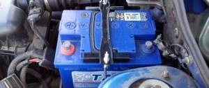
– remove the wire from the negative terminal of the battery;
– raise the rear seat;
– remove the metal hatch plug in the rear floor to gain access to the pump cover;
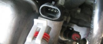
– disconnect the electrical connector (Fig. 1);
– disconnect the quick-release fitting of the fuel supply pipeline (green);
– disconnect the quick-release fitting of the drain pipeline (red). Plug the holes to prevent dirt from entering;
– fix the markings to align the elements of the assembly (Fig. 2). Place a wide slotted screwdriver on the protrusion of the round nut and, lightly hitting it with a hammer, loosen the nut and then unscrew it by hand;
– carefully remove the fuel pump and level sensor assembly from the tank (Fig. 3);
– inspect the sealing gasket. If it is free of defects, it can be reused.
Rice.
2. Marking of the fuel pump cover: 1 – round nut securing the fuel pump;
2 – mark on the round nut; 3 – three marks on the fuel tank; 4 – mark on the fuel pump cover 3. Checking the fuel pump supply
Operating procedure:
– relieve the fuel pressure in the system;
– raise the rear seat;
– remove the metal hatch plug in the rear floor to gain access to the fuel pump cover;
– Reinstall the fuel pump activation relay;
– disconnect the green quick-release fitting from the fuel pump cover and use a suitable hose to connect the pump to a 2-liter beaker;
– turn on the fuel pump using a diagnostic tool or by installing a jumper in the fuel pump relay between pin 1 and “+” of the power circuit;
– measure the pump flow, which should be 60–80 l/h.
After taking the measurement, reinstall the removed elements.
Checking fuel pressure
Operating procedure:
– remove the protective casing of the fuel distribution rail;
– relieve the fuel pressure in the system;
disconnect the fuel supply line and connect the tee (Mot. 1311–08) with a control pressure gauge;
– start the engine to activate the fuel pump;
– check the pressure on the pressure gauge, which should be constant and amount to (3.5 ± 0.06) bar.
Rice. 3. Measuring fuel supply pressure: 1 – fuel supply pipeline; 2 – control pressure gauge
3. Removal and installation of the electronic control unit (ECU)
The unit is installed on the left side of the engine compartment behind the battery.
Removal procedure:
– remove the wire from the negative terminal of the battery;
– disconnect the fastening of the power steering reservoir from the engine shield and move it to the side;
– unscrew the bolts securing the block and remove it together with the bracket;
– remove the bracket from the block;
– disconnect the contact connector from the unit.
Rice. 4. Fuel injection ECU contact location
Installation of the ECU is carried out in the reverse order of removal, and do the following:
– securely connect the connector;
– if a new unit is installed, it must be programmed to ensure the immobilizer operates. To do this, turn on the ignition for a few seconds, then turn it off. Remove the ignition key to activate the immobilizer. After 10 seconds, the red immobilizer activation indicator should start flashing.
5. Checking and adjusting the injection system
If a malfunction occurs in the fuel injection system, you should first check the reliability of all contact connectors and connections
.
Make sure the air and fuel filters are clean and the crankcase ventilation hoses and vacuum hoses are intact and clean.
Engine compression should be normal and spark plugs should be in good condition. Check that the ignition timing is set correctly.
If after the above checks and adjustments there is no improvement in engine performance, you should contact a specialized service station to check the car. Specialists, using a diagnostic tool connected to a special connector located under the ashtray of the center console, display information about any injection system unit on the device screen. If, while driving the car, the “Injection system malfunction” indicator lights up in the instrument cluster or it does not go out 3 seconds after turning on the ignition, this may indicate a defect in the following devices:
- pressure meter;
– throttle potentiometer;
– nozzles;
– idle speed regulator;
- speed sensor;
– electromagnetic valve of the exhaust gas recirculation system;
- Automatic transmission.
Some components of the fuel injection system can be checked
, measuring their parameters, however, the performance of a number of components cannot be assessed without
special diagnostic equipment.
Experienced car enthusiasts, if they have a tachometer and a gas analyzer, can check the CO level in the exhaust gases at idle. However, if it turns out that these characteristics require adjustment, you will have to contact a specialist to carry out further checks using specialized equipment. Neither the CO level nor the idle speed are adjustable. If they are incorrect, the injection system is faulty.
Checking the content of toxic substances is carried out at a coolant temperature above 80 ° C after stable engine operation at a rotation speed of 2500 rpm for approximately 30 s.
Homework:
1. Read and analyze the lecture.
2. Answer security questions
Test questions for self-test:
A few words about the procedure for working with wiring
At the end of today’s article, we’ll look at exactly how you should proceed if you want to change the wiring. As an example, let's take standard models of the VAZ brand - 2110, 2109 and the like. So, to competently work with car data electronics you will need:
- First, prepare for repair procedures. The implementation of this goal lies through:
- Purchasing the required wiring and devices;
- Search for the necessary connection diagrams;
- Selection of auxiliary tools: harnesses, fasteners, gloves for work, etc.
- After this, acting according to the diagrams of the currently installed electronics, we completely remove it. Naturally, before this you need to turn off the engine, disconnect the battery and put on gloves;
- Then the actual replacement of the VAZ wiring begins. Here you also need to act taking into account the connection diagrams. First of all, we connect the injector wiring according to the principle “from the oldest element to the youngest”. Next, we connect the main wiring outputs (ECU contacts) with the current source, and at the end we connect other electronics.
This is interesting: What could cause a malfunction?
Of course, the noted procedure is only generalized, but, in general, compliance with it and compliance with the described rules for working with car wiring is the key to the success of such repairs. We hope that today's material was useful to you and provided answers to your questions. Good luck in maintaining and operating your car!
Post navigation
Tip: Before doing this, slide the latches located under the dashboard. In addition, the problem may also be a failure of the distributor.
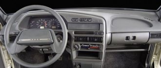
Tips for high panel owners
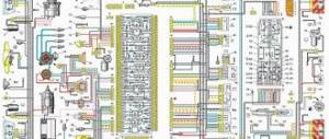
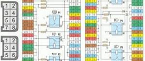
Failed fuse box 2. There you can find in the photo detailed layout diagrams of the injector and ECU.
Most likely, the wiring has broken, the contacts on the generator have oxidized, or the drive belt is broken. Unlike a carburetor circuit, where the pedal directly controls the damper, in injection engines the pedal is not connected to the actuator; IAC idle speed regulator. If you have a VAZ injector with a low or high panel, then there is a possibility that the cause of the malfunction is the operation of the ECM. Did you like the article? Connection diagram for starter VAZ, VAZ, VAZ A - pull-in winding; B - holding winding; 1 - starter enable relay; 2 — mounting block; 3 — ignition switch; 4 - generator; 5 - battery; 6 — starter Fig.
Share with friends: You may also be interested. This car had a 4-door, 5-seater sedan body and a rear overhang extended by a mm. If the engine fails to start, the condition of the electrical circuits is first checked. Before you begin assembling the heater, be sure to lubricate the places where the dampers are attached with a special grease. One of the very first things to check is the DPKV for the serviceability of the connector and wiring. How does the cooling fan turn on?
DEVICE AND PRINCIPLE OF OPERATION (using the example of an electronic distributed injection system)
Modern injection engines have an individual injector for each cylinder. All injectors are connected to the fuel rail, where the fuel is under pressure, which is created by an electric fuel pump. The amount of fuel injected depends on the duration of the injector opening. The opening moment is regulated by an electronic control unit (controller) based on the data it processes from various sensors.
The mass air flow sensor is used to calculate the cyclic filling of the cylinders. The air mass flow is measured, which is then recalculated by the program into cylinder cyclic filling. If a sensor fails, its readings are ignored and calculations are made using emergency tables.
The throttle position sensor is used to calculate the load factor on the engine and its change depending on the throttle valve opening angle, engine speed and cyclic filling.
The coolant temperature sensor is used to determine the temperature correction of fuel supply and ignition and to control the electric fan. If the sensor fails, its readings are ignored, the temperature is taken from the table depending on the engine operating time.
crankshaft position sensor serves for overall system synchronization, calculating engine speed and crankshaft position at certain points in time. DPKV - polar sensor. If turned on incorrectly, the engine will not start. If the sensor fails, the system cannot operate. This is the only “vital” sensor in the system that makes it impossible for the vehicle to move. Failures of all other sensors allow you to get to the service center on your own.
The oxygen sensor is designed to determine the oxygen concentration in the exhaust gases. The information that the sensor provides is used by the electronic control unit to adjust the amount of fuel supplied. The oxygen sensor is used only in systems with a catalytic converter under Euro-2 and Euro-3 toxicity standards (in Euro-3 two oxygen sensors are used - before the catalyst and after it).
The knock sensor is used to monitor knock. When the latter is detected, the ECU turns on the detonation damping algorithm, quickly adjusting the ignition timing.
Listed here are only some of the basic sensors required for the system to operate. Sensor configurations on different vehicles depend on the injection system, toxicity standards, etc.
Based on the results of polling the sensors defined in the program, the ECU program controls actuators, which include: injectors, fuel pump, ignition module, idle speed regulator, canister valve for the gasoline vapor recovery system, cooling system fan, etc. (all again depends on the specific models)
Of all the above, perhaps not everyone knows what an adsorber is. The adsorber is an element of a closed circuit for recirculating gasoline vapors. Euro-2 standards prohibit contact of the gas tank ventilation with the atmosphere; gasoline vapors must be collected (adsorbed) and, when purged, sent to the cylinders for afterburning. When the engine is not running, gasoline vapors enter the adsorber from the tank and intake manifold, where they are absorbed. When the engine starts, the adsorber, at the command of the ECU, is purged with a flow of air sucked in by the engine, the vapors are carried away by this flow and are burned in the combustion chamber.