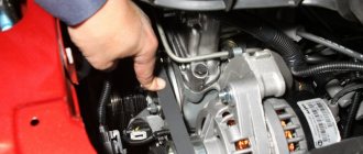
For normal operation of the car, you need to promptly diagnose and repair the Chevrolet Niva chassis with your own hands or at a service center. To save money, it is better to do it yourself according to the instructions that we have prepared for you in this material.
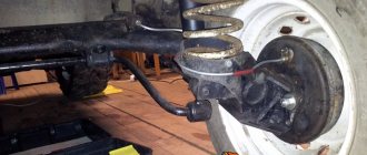
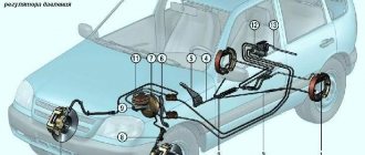
The front suspension of the domestic SUV has an independent design. On each side there are two wishbones, coil springs, telescopic shock absorbers and anti-roll bars.
Diagnostics of Niva chassis
To check the technical condition of the car's suspension elements, you need to lift it on a lift or place it over a hole and go down. It is important to suspend the front wheels. The rubber elements should not show any signs of aging or mechanical damage. There should also be no cracks, signs of aging, one-sided bulging of the rubber or its separation from the reinforcement on the rubber-metal hinges. All damaged parts must be replaced.
Be sure to check the condition of the protective covers of the ball joints and supports. If they are damaged, you will have to replace the entire hinge assembly.
Take a good look at the rubber cushions of the upper hinges and check the condition of the rubber bushings of the lower hinges. Do not forget to inspect the rubber-metal bushings of the levers - lower and upper. Inspect the rubber bushings of the anti-roll bar and the quality of the attachment of the stabilizer brackets to the arms and side members.
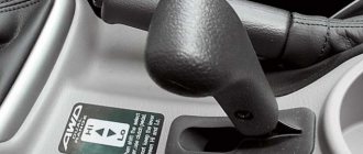
60 REAR SUSPENSION Niva Chevrolet Fig. 6.2. Rear suspension parts: 1 – transverse rod; 2 – lower spring gasket; 3 – lower longitudinal rod; 4 – bolt for fastening the lower rod; 5 – rubber bushing of the hinge; 6 – spacer sleeve; 7 – nut; 8 – bracket; 9 – upper longitudinal rod; 10 – additional compression progress buffer; 11 – upper spring gasket; 12 – compression stroke buffer; 13 – rear shock absorber The rear suspension of the car is dependent, includes a guide device, elastic elements and devices that dampen body vibrations. The rear axle beam is pivotally connected to the body using reaction rods - two lower 3 (Fig. 6.2) and two upper 9 longitudinal rods and one transverse rod 1. The longitudinal rods transmit pushing and braking forces from the drive wheels through the rear axle beam to the body. The cross bar keeps the body from moving laterally. The reaction rods are attached to the body brackets and the rear axle beam through rubber-metal hinges, which are structurally identical and differ only in size. The hinge consists of a rubber bushing 5 installed in the eye of the rod, a spacer bushing 6, which passes through the hole of the rubber bushing, a thrust washer and a bolt securing the rod. The elastic elements of the suspension consist of twisted cylindrical springs, two main buffers 12 of the compression stroke and an additional compression buffer 10. The spring installed in the suspension rests with its upper end on the support cup through a rubber insulating gasket 11, which is placed in a stamped steel cup of the body. The lower end of the spring rests on the cup of the rear axle beam through an insulating gasket 2. The main buffers 12 are installed inside the springs and secured with a mushroom-shaped clamp in the holes of the upper supports. The additional buffer 10 is mounted on a bracket bolted to the underbody. The damping device consists of two hydraulic shock absorbers. Rear suspension from the bottom behind the car: 1 – rear axle beam; 2 – compression progress buffer; 3 – additional compression progress buffer; 4 – transverse rod Rear suspension from below in front: 1 – spring; 2 – upper longitudinal rod; 3 – lower longitudinal rodChecking the technical condition of the rear suspension
on a car Check the condition of the rear suspension from below the car, mounted on a lift or inspection ditch. The following are not allowed on rubber suspension parts: – signs of rubber aging; - mechanical damage. Signs of aging, cracks, and one-sided bulging of the rubber mass are not allowed on rubber-metal hinges. Replace defective parts. Check for mechanical damage (deformation, cracks, etc.) to the suspension elements, especially the suspension bars and the crossbar bracket on the body. When checking, carefully inspect: 1. Rubber bushings of the lower hinges and... 2. ...cushions of the upper hinges of the shock absorbers. 3. Shock absorbers. Liquid leaks and “sweating” are not allowed.
SHOCK ABSORBERS Design features The shock absorbers of the front and rear suspensions differ in size and method of fastening the upper part. In addition, the front shock absorber has different performance parameters. The internal structural elements and operating principle of shock absorbers are almost the same. Rice. 6.3. Shock absorbers of the front and rear suspensions: 1 – lower eye; 2 – compression valve body; 3 – compression valve discs; 4 – throttle disk of the compression valve; 5 – compression valve spring; 6 – compression valve cage; 7 – compression valve plate; 8 – recoil valve nut; 9 – recoil valve spring; 10 – shock absorber piston; 11 – recoil valve plate; 12 – recoil valve discs; 13 – piston ring; 14 – recoil valve nut washer; 15 – throttle disc of the recoil valve; 16 – bypass valve plate; 17 – bypass valve spring; 18 – restrictive plate; 19 – reservoir; 20 – rod; 21 – cylinder; 22 – casing; 23 – rod guide bushing; 24 – reservoir sealing ring; 25 – rod seal race; 26 – rod seal; 27 – gasket of the rod protective ring; 28 – rod protective ring; 29 – tank nut; 30 – upper shock absorber eye; 31 – nut securing the upper end of the front shock absorber for the suspension; 32 – spring washer; 33 – shock absorber mounting pad washer; 34 – pillows; 35 – spacer sleeve; 36 – front suspension shock absorber casing; 37 – rod buffer; 38 – rubber-metal hinge The rear shock absorber consists of a reservoir 19 (Fig. 6.3) with an eye, a compression valve (items 2, 3, 4, 5, 6, 7), a working cylinder 21, a rod 20 with a piston 10 and recoil and bypass valves and casing 22 with eyelet. Reservoir 19 is made of a steel pipe, to the lower end of which eye 1 is welded, and in the upper part a thread is cut for nut 29. The compression valve body 2, assembled with valve discs, is inserted into the recess of the eye. It is pressed against the recess by working cylinder 21. The annular space between the reservoir and the cylinder is filled with liquid. Inside the working cylinder there is a rod 20 with a piston 10. The piston has vertical channels located in two circles. The channels on the small circle are closed from below by discs 12 and 15 of the recoil valve, and on the large circle - from above by plate 16 of the bypass valve. The compression valve is located at the bottom of the cylinder. In the valve body 2 there is a socket, to which disks 3 and 4 are pressed by a spring 5 through a plate 7. The throttle disk 4 has a cutout through which the liquid is throttled at a low speed of movement of the piston. In the lower part of the valve body there is a cylindrical groove and four vertical channels, and in cage 6 there are six side and one central holes through which the liquid passes from the reservoir to the cylinder and back. A guide bushing 23 is installed on top of the cylinder, which is sealed in the reservoir with a ring 24, and the output of the rod is with an oil seal 26 with a holder 25. All parts located in the upper part of the cylinder are tightened with a nut 29. Rubber-metal hinges 38 are pressed into the shock absorber eyes. USEFUL ADVICE For repairs Shock absorbers require special equipment; in addition, this work requires the performer to have experience in such work. Repairing a shock absorber in a garage usually does not lead to the desired result. Therefore, have shock absorbers repaired in a specialized workshop. Checking shock absorbers on a car The condition of shock absorbers is checked: – by external inspection. If shock absorber fluid leaks are detected, remove the shock absorbers for repair in specialized workshops; – subjectively – in terms of the effectiveness of damping vehicle vibrations when driving. If the efficiency of vibration damping decreases or frequent hard impacts occur during rebound and compression (“breakdowns”) of the suspension, remove the shock absorbers for inspection and repair in specialized workshops; – the most correct way is to check shock absorbers on special stands (both shock absorbers installed on the car and those removed). HELPFUL ADVICE Replace faulty shock absorbers only in pairs (front, rear) or as a set (all four). 1. Place the car on a level surface (or a level garage floor). Turn off the engine and engage the gearbox in 1st gear or reverse gear. Do not use the parking brake. 2. Rock the car around the corner (wing) up and down with an amplitude of at least 50 mm. 3. At the bottom point, release your hands. 4. If the car made one oscillation up, then half a move down and stopped, the shock absorber is working. 5. Repeat steps 2–4 for the remaining three shock absorbers. Checking shock absorbers on a stand To determine the performance of the shock absorber, remove it from the car (see subsections “Front Suspension” and “Rear Suspension”) and check its working diagram on a dynamometer stand. Take operating diagrams according to the instructions supplied with the stand, after performing at least 5 working cycles at a temperature of the shock absorber working fluid of 20±5 °C, a stand flywheel rotation speed of 60 min-1 and a rod stroke length of 100 mm for the front shock absorber. Rice. 6.4. Shock absorber operating diagram: 1 – force during recoil stroke; 2 – force during the compression stroke The curve of the diagram (Fig. 6.4) should be smooth, and at the transition points (from the recoil stroke to the compression stroke) without sections parallel to the zero line. Evaluation of results using the diagram. The resistance point of the recoil stroke at a scale of 47 N (4.8 kgf) per 1 mm should be from the zero line at a distance A equal to: 33.3–40.7 mm for front shock absorbers, 23.5–30.5 mm for rear shock absorbers. The highest point of the compression stroke curve at the same scale should be located from the zero line at a distance B equal to 3.5–6.5 mm for front and rear shock absorbers. The control values of the ordinates on the diagrams of the front and rear shock absorbers are specified for cold shock absorbers at a shock absorber fluid temperature of 20±5 °C. After checking, remove the shock absorber from the stand and, if necessary, reassemble and replace damaged parts. Repeat the test to ensure the shock absorber is working properly. Next page""""""
- 10. 11. 12. 13. 14. 15. 16. 17. 18. 19. 20. 21. 22. 23. 24. 25. 26. 27. 28. 29. 30. 31. 32. 33. 34. 35. 36. 37. 38. 39. 40. 41. 42. 43. 44. 45. 46. 47. 48. 49. 50. 51. 52. 53. 54. 55. 56. 57. 58. 59. 60. 61. 62. 63. 64. 65. 66. 67. 68. 69. 70. 71. 72. 73. 74.
coming
Adjusting the wheel bearing clearance
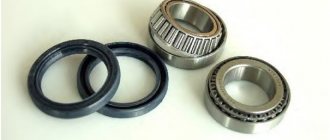
Wheel bearing
If the clearance in the front wheel wheel bearings is increased, you will feel vibration in the steering wheel at certain speeds. Because of this, the tires will wear unevenly (spots will form), and the life of the bearings will be reduced. Their service life can also be reduced by the complete absence of clearance, which causes tight rotation of the hub. The clearance in the wheel bearings of the front wheels of the Chevrolet Niva should not exceed 0.15 mm. To adjust the front bearings, use a wheel wrench, a 27mm wrench, and a hammer.
Try swinging a suspended wheel in a vertical plane. If you feel any play, you will have to adjust the gap. Also ask a helper to press the brake and hold the pedal while you swing the wheel vertically again. If the play is gone, there is definitely some play in the bearings.
Remove the decorative cap and unscrew the hub locknut. Holding it with a knob to prevent it from turning, unscrew the nut. In the process of adjusting the hub when repairing the Niva chassis, it is recommended to install new hub nuts, since the old nuts may, even after adjustment, take the old position, and you will not lock it with sufficient reliability. As a last resort, you can take a used nut from another car.
Screw and tighten the hub nut to a torque of 19.6 Nm, turning the hub 90 degrees in two directions 2-3 times. This will ensure the bearings self-align. Loosen the adjustment nut and retighten it to 6.8 Nm, then back it out 25 degrees.
Push the collar of the nut into the two grooves on the outer drive joint journal, thus locking the hub nut. Install the removed parts in reverse order.
After adjusting the clearance in the Chevrolet Niva bearings, make sure that the wheel rotates easily. The final adjustment check should be assessed by the degree of heating of the hubs after traveling one kilometer without braking.
Replacing grease in wheel bearings
When repairing the Chevrolet Niva suspension, the lubricant in the bearings should be changed at the intervals indicated in the service manual. If there is little lubricant or it is dirty, the bearings will wear out quickly. To work, you will need a pair of 13mm wrenches, a wrench for wheel bolts, a torque wrench, a hammer, a screwdriver, Litol-24 and a container for washing the elements.
Lubrication process
First you need to remove the wheel and brake pads. The caliper is dismantled without disconnecting the hydraulic hoses. Just move it to the side and hang it on a wire so as not to load the hose. Pull the rubber holder out of the hose bracket.
Replace the grease in the bearings at the intervals specified in the service book. If the lubricant is insufficient or contaminated, the bearings will quickly fail. To replace, you will need 13" keys (two), a torque wrench, a wrench for wheel nuts, pliers, a screwdriver, a hammer, clean Litol-24 lubricant, and a container for washing parts. Remove the wheel and brake pads.
Next, you need to loosen the pin nut of the outer joint of the side link and unscrew it. Install the puller and press out the steering joint pin that is held in the steering arm boss. Unscrew the three nuts of the bolts that hold the ball joint and the support on the arms, and unscrew the hub nut. Remove the bolts and remove the steering knuckle and joint assembly. Using a suitable bushing, press the hub out of the bearing races.
Use a screwdriver to pull the oil seal out of the hub, but keep in mind that it will have to be replaced after this. Pull out the spacer and inner races of the bearing, and then wash all the elements with kerosene and fill the internal cavity with lubricant. Also apply Litol to the inner and outer rings of the bearings.
Insert the inner and spacer rings into the steering knuckle, and then press the oil seal into the steering knuckle socket. Reinstall everything in the reverse order and adjust the wheel bearing clearance according to the instructions described above.
Replacing wheel bearings
Replacing the Niva Chevrolet wheel bearing on the front wheel is quite difficult work, but we will tell you how to do it further. The need for this may arise if noise occurs when the wheel rotates, as well as the inability to achieve the desired clearance using adjustments.
To dismantle and install the front hub bearings, you will need a wheel wrench, a screwdriver, a hammer, a wrench for 13 and 17, a bit, a torque wrench, a mandrel for pressing the oil seal, Litol-24, kerosene and a container for washing the elements.
Bearing replacement
Dismantle the steering knuckle and pull out the hub, spacer ring, oil seal and inner races with the bearing, and then thoroughly wash everything with kerosene. Inspect the inner and outer races of the bearings and check the condition of the running surfaces of the rollers.
Noticeable wear of cages, rings, rollers, all kinds of chips and cavities - all this is unacceptable. If all these defects are discovered during the repair of the Chevrolet Niva suspension, the bearings need to be replaced.
Using a punch and a hammer, begin to lightly tap around the perimeter of the outer ring and press the ring out of your fist. Then, with gentle blows with a hammer along the perimeter of the ring through a soft metal drift, you need to press the outer ring of the new outer bearing until it stops against the shoulder of the seat in the steering knuckle. It is necessary to fill the internal cavity with grease and apply it to the outer rings of the bearings.
Install all dismantled elements into the steering knuckle. When repairing the Niva suspension, the steering knuckle must be installed in the reverse order of disassembly. After this, adjust the clearance in the wheel bearings.
Niva front suspension operation
Operation of the Niva front suspension in extreme conditions.
Read news about the new Niva
- Front lower suspension arms VAZ-2121 - Drawings, 3D Models, Projects, Cars and automotive industry (Car service)
- Suspension lift in the field yourself | Niva Repair
- Niva 2121 suspension lift do-it-yourself drawings
- Tuning Niva 2121 with your own hands: body, interior, suspension
- Chevrolet Niva suspension lift: rules, methods and step-by-step instructions
- Do-it-yourself Niva suspension lift. How to lift the front and rear suspension of a Niva car?
- Diagram and location of the fuse box Niva VAZ-21213 and 21214
- Timing marks on a Chevrolet Niva car
Replacing the upper ball joint
Repairing the front suspension of a Chevrolet Niva sometimes involves replacing the hinge. To dismantle and install it, you will need keys 13 and 22, a wheel wrench for removing wheels, a support in the form of a jack, a mounting blade, a metal brush and a hammer.
First you need to remove the wheel and place a support under the lower arm, and then lower the car. This way the suspension will be loaded and the position of the arms will correspond to their position under load. Clean the dirt from the ball joint, remove the brake hose clamp from the bracket
Loosen the hinge pin nut and unscrew it completely. If the pin rotates due to wear or a loose cone fit, the lever should be pressed down with a pry bar, resting against the last coil of the spring.
Remove the brake hose bracket and install a ball joint remover, and then press the pin out of the steering knuckle boss.
Unscrew the three nuts that secure the hinge to the lever and disconnect the hinge from it. Installation of the upper ball is carried out in the reverse order of disassembly.
Signs of trouble
Chevrolet Niva suspension parts are designed for different service life.
The levers, beam and anti-roll bar do not need to be changed even after 100-200 thousand kilometers.
But rubber-metal hinges, boots and bushings gradually lose their properties even while parked.
VAZ-2123 owners have to deal with the following malfunctions:
- Wear of silent blocks, ball joints.
- Damage or cracking of anthers.
- Reduced performance of shock absorbers.
- Breakage of jet rods.
In addition to replacing faulty parts, it is necessary to regularly check and adjust the angles of the front wheels.
Otherwise, the car's handling deteriorates, and the tires begin to wear out rapidly. Wheel alignment is checked every 10-15 thousand kilometers and after very strong impacts when falling into road potholes.
Some problems can be identified by hearing while driving. Worn ball joints or silent blocks, faulty shock absorbers or broken rods knock, squeak or ring when driving on uneven roads.
In addition to extraneous sounds, suspension malfunctions manifest themselves as follows:
- Rocking or jumping of the body when driving over uneven surfaces.
- Pulling the car to the side.
- Increased braking distance.
- Deterioration in controllability.
- Accelerated or uneven tire wear.
We are replacing the lower ball joint
Lower ball
If, when diagnosing the chassis of a Chevrolet Niva with your own hands, you determine the need to replace the ball joint, you will need a small set of tools:
- keys for 13, 22 and 27;
- wheel nut wrench;
- metal brush;
- mount;
- jack;
- hammer.
Remove the wheel and place a support under the lower arm, thereby loading the suspension and aligning the position of the arms. Remove the hub cap and unscrew the nut. It is always tightened very tightly, so use a head with a reliable knob.
Unscrew the nut that is screwed onto the ball joint pin, and then press the pin out of the steering knuckle boss. Unscrew the nuts of the bolts that hold the lever on the support and remove the bolts by moving the steering knuckle away. Remove the wheel hub from the splines of the outer wheel drive joint. Remove the ball joint and then install in the reverse order of assembly.
Pros and cons of chassis
Significant advantages are:
- Components for the Chevrolet Niva chassis are always available at most dealers. The cost of these spare parts is much lower than that of competitors' cars.
- High maneuverability in all conditions.
- The chassis has a large departure angle of 350 degrees and entry angle of 370 degrees. The presence of such characteristics allows you to overcome any obstacles on the road.
- Smooth and easy movement on the highway.
- Soft ride in off-road conditions thanks to reduction gear and forced locking of the center differential.
Along with the benefits that the owner of Shnivy receives, he is also rewarded with the following disadvantages, by the way, coming from the advantages:
- Noticeable vibration of the body when driving, especially from the rear axle.
- High fuel consumption due to the heavy rear suspension and permanent all-wheel drive. For example, a car engine “eats” about 8 liters of gasoline on the highway and 14 liters in the city. Such consumption, for example, is equal to the fuel requirement for a Toyota LC 200.
- The chassis is equipped with poor quality seals, bushings, silent blocks and ball joints. You need to pay attention to these parts after 15,000-20,000 km.
- Wheels move to the side when driving after 25,000 km due to broken wheel bearings.
And also interesting: Niva 2121, Niva 2131 and Niva Chevrolet. Let's compare?
Along with the benefits that the owner of Shnivy receives, he is also rewarded with the following disadvantages, by the way, coming from the advantages:
- Noticeable vibration of the body when driving, especially from the rear axle.
- High fuel consumption due to the heavy rear suspension and permanent all-wheel drive. For example, a car engine “eats” about 8 liters of gasoline on the highway and 14 liters in the city. Such consumption, for example, is equal to the fuel requirement for a Toyota LC 200.
- The chassis is equipped with poor quality seals, bushings, silent blocks and ball joints. You need to pay attention to these parts after 15,000-20,000 km.
- Wheels move to the side when driving after 25,000 km due to broken wheel bearings.
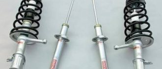
Changing front shock absorbers
It is not so difficult to change shock absorbers on a Chevrolet Niva with your own hands. This has to be done when a leak occurs or vibration damping deteriorates when driving over uneven surfaces. Worn shock absorbers are always replaced in pairs or all four at once. To dismantle and install the shock absorber you will need 17 and 6 keys.
Using one 17mm wrench, secure the shock absorber rod from turning, and with another one, unscrew the nut and remove the thrust washer with the rubber cushion. Unscrew the bolt nut on the lower hinge and pull out the bolt, after which you can remove the shock absorber. Remove the lower cushion from the shock absorber rod and inspect the condition of the rubber cushions and shock absorber.
Remove the lower hinge, and if necessary, replace the cushion and bushing of the lower hinge. When repairing the suspension, Chevrolet Niva shock absorbers are installed in the reverse order. Before installation, the rod must be pulled out to its full stroke. When working on a lift, you need to lower the car before assembling the upper mount so that the suspension is loaded under the weight of the car.
Installing a lift kit on Niva 2121
Hello, dear friends! Today I propose to talk to you about the elevator kit for the Niva. This could be a Chevrolet Niva, that is, series 2123, or the more “our” Niva Urban, 2131 or 4x4, and representatives of the 2121 series, that is, 21213, 21214. It all depends on what kind of car you have at your disposal.
Russia, Ukraine, Belarus and a number of other countries are the greatest admirers of Niva cars. They are affordable and provide many benefits.
Some people prefer to do everything themselves. I can’t say that modifying the front and rear suspension of a Niv car will be an easy job in a minute. No, you will have to spend a lot of effort, time and patience on this.
You can find out how much such a service costs at a service station. The price for a professional lift is steep, so not every owner of a not-so-expensive crossover like the Niva is willing to spend that kind of money, having the opportunity to do everything themselves. And if you put a power bumper and an expeditionary trunk on top, it will turn out great. At least now on a round-the-world trip on Niva.
Increasing the ground clearance of the VAZ 2121 (lifting) allows you to increase the vehicle's off-road capability. Thanks to simple manipulations, the ground clearance increases significantly by changing the suspension height (the Niva lift kit will help you here, which makes the work very easy to do even with your own hands without the help of a service center) and installing slightly larger diameter wheels.
Also interesting: Tuning Niva: 145 photos of ideas on how to improve the VAZ 2121 with your own hands "
Lifting - increasing the vehicle's ground clearance by upgrading the suspension. Performed in order to increase cross-country ability.
We propose to consider this issue in more detail.
As a rule, a lift kit for Niva 2121 includes:
- Rear and front springs.
- A set of spacers for the upper ball joint.
- Front oil shock absorber.
- Adjustable Panhard rod.
How to replace front suspension springs?
Replacing Chevrolet Niva springs may be necessary in case of mechanical damage or severe sagging. Signs of precipitation include:
- violation of smoothness;
- suspension breakdowns on uneven surfaces;
- noticeable distortion of the front part of the car;
- difference in height of the front and rear parts of the car;
- traces of collision of spring coils.
Front springs
To dismantle and install the front springs, you need two 13, two 17 and one 24 wrenches, as well as a jack and a wrench for unscrewing the wheel nuts. First, remove the wheel and loosen the lower arm axle nut with a wrench.
Unscrew the nut of the bolt that secures the shock absorber from below and remove the bolt. Next, unscrew two more nuts of the stabilizer pad bracket and remove the bracket. Raise the front suspension with a jack to release the compression stop. Next, unscrew the three nuts on the ball joint mounting bolts and remove the bolts.
Slowly lowering the lever, you need to release the spring and remove it. Next, remove the lower and upper spring gaskets. If necessary, the compression stroke limiter must be removed. When repairing the Chevrolet Niva suspension, install the springs in the reverse order.
Niva suspension lift yourself drawing
We will tell you how to properly perform tuning modifications in this material.
Do-it-yourself elevator - drawings, diagrams, sizes, types of kits. Lifting varies in the degree of intervention in the standard structure. For some, it is enough to raise the SUV by a few centimeters, and for others by as much as 20.
Extreme tuning – maximizing cross-country ability for traveling on severe off-road conditions.
- Regular jack
- Hijack jack
- Spring puller
- Balloon wrench
- Ratchet socket set
- Set of open-end wrenches
- Mount
- Wooden deck (stump)
It is advisable to perform such work with a partner. First of all, it's safer. Secondly, some lifting work is performed with four hands. Let's take the front suspension as an example.
Raise the front end. You can safely cling to the standard bumper, only the jack is installed under the pipe securing it. By removing the wheel, we get full access to the lever and spring. The front suspension 21214 is made using a double wishbone design, which simplifies the task.
The lever travel is limited by the shock absorber. Unscrew its fastening and move it to the side. Next you need to free the suspension from the anti-roll bar. The mounting bolts may become stuck due to corrosion, so we will use a penetrating liquid (such as WD-40). The stabilizer silent block clamp can be pryed off with a pry bar.
Then disconnect the hub from the lower arm. To do this, you need to jack up the suspension and fix the steering knuckle of the wheel. You can tie it with wire. Then unscrew the 3 mounting bolts and release the ball joint.
We fix the spring with ties and lower the jack. We remove the old elastic element. In some cases, it is enough to simply lower the lever with your foot, and the spring will come out without the use of ties.
Remove the upper support rings from the old springs. With their help, the elastic element is centered in the cups.
They come together easily with a hammer and screwdriver. We install the rings on new, longer springs. We put the elastic elements in their regular places and jack up the lower arm until it is completely aligned with the lower cup. At the same time, an assistant centers the shock absorber eye and moves the steering knuckle to the mounting location of the lower ball joint. We tighten the ball “triangle” and attach the shock absorber mounting axis.
By manipulating the jack, we “catch” the mounting holes for the stabilizer bar clamp. With its bolts it should get into the normal place without distortion. After such modernization, the clearance increases by 30-50 mm. This is enough to install wheels of larger diameter, and the bottom will still rise above the ground.
The rear axle of the Niva can be lifted by installing spacer supports of increased height. When using a size of up to 50 mm (according to changes in front end height), no modifications to the rear axle are required. By lifting the rear axle, maintenance can be carried out on the axle and brake system.
The handbrake cable may need to be replaced. It is lengthened by a couple of centimeters. Otherwise, the Niva lift will lead to increased wear of the brake pads in the rear drums. Disconnect the lower shock absorber mounts and lower them until the springs stretch.
We take out the elastic elements and knock off the support rings from them. We clean the upper cup and carry out anticorrosive treatment. We install new supports of increased size and seat the springs using a jack. We fasten the shock absorbers, assemble the axle, and mount the wheels.
Also interesting: Niva Chevrolet transfer case: device, connection diagram and how to use?
Such a lift will not arouse suspicion among traffic police inspectors, and the cross-country ability of your NIVA 2121 will improve. No drawings, much less homemade parts, are required. You buy new springs and about the rates, the rest is a matter of technology. Labor costs for an elevator of one NIVA are two people/one day off.
Making a Niva-2121 elevator with your own hands, the drawings, the dimensions of which are freely available, will not be difficult. Thanks to such a trick, you can make your car more stable on the road and overcome a lot of obstacles with it. Of course, to bring a truly high-quality Niva elevator to life with your own hands, you will have to work hard.
The process will take time and require effort, because even the easiest elevator requires a significant immersion in the technical aspects of the issue. However, the end result will live up to all expectations, allowing the modest Niva to show its exceptional side.
For lovers of hunting, fishing and country travel, as well as those eager to try themselves and their own “Niva” in driving a vehicle in difficult-to-pass places, we have the opportunity to offer an increase in ground clearance, which increases the cross-country ability of your car.
Niva tuning – suspension lifting.
At the moment, there are at least 6 types of suspension lifting for Niva and Sh/Niva, each is interesting in its own right and is negotiated during the preparation of the car for “off-road” at the request of the visitor, taking into account the distinctive features of the operation of his car and the sizes of wheels and tires he uses wants to put it on his car.
We often use a kit from the Russian club 'Korovka' as a base. This lift kit was made at the factory and was tested at competitions in Russia. The ground clearance increases by 5 centimeters, which actually makes it possible to install R15 235/75 or R16 235/70 tires (on the right wheels). In addition, this will provide a rise of another 4 centimeters.
In total, the increase in ground clearance will be 9-10 cm! In this version, “NIVA”, without loss of comfortable qualities, has the ability to be used both on paved highways and off-road, being in no way inferior to foreign-made SUVs.
Consequently, at the lower point of the RZM the clearance is 25 cm, and at the cut of the threshold - 44.5 cm.
Front suspension lift.
The lift is performed by installing targeted washers under the lower spring pad (they create a sufficient angle for the front spring). Under the upper arm (between it and the ball) another spacer washer is placed (i.e., we unload the arm).
The levers of the steering knuckles are swapped and the tips of the control rods already go from top to bottom (since subsequently the work done before, when the rod is fully turned, they will rest against the stabilizer, although at the request of the visitor it is possible to leave it as it was by changing the fastening of the stabilizer).
During lifting work, it is often necessary to change shock absorbers, springs, and resins on request. spacers, internal CV joint boots on tuning suspensions modified for this type of lift and create adjustments. spring bumpers.
Lifting the Niva suspension at the rear.
The lift is carried out by installing new rear spring cups, which are bolted on top of the standard ones, and brackets for moving the mounting points of the rear shock absorbers up 5 centimeters (bolted).
The short upper rods of the rear axle are lengthened or made adjustable (for easy rotation of the shank, so as not to bite the crosspiece), the reaction rods of the rear axle are either reinforced with an angle or installed double; at the request of the visitor, a rear axle stabilizer “Tehnomaster” (Tolyatti) is added, although it will be needed adjust to the elevator machine, digest.
Similarly, it is preferable, on lifted cars, to use a rear CV joint. Those who begin to lift old or worn-out cars need to remember about the internal CV joints (the balls leave their place) and will need to prepare for their replacement. The solution to this difficulty is quite possible by reducing the drive angle by untying the front axle.
The outer CV joints are too little susceptible to this, it will be worse for them if the wheel becomes larger in offset, width and weight, and then they can “crunch”. Although even then the hub bearing has a hard time, especially if it had play before.
Also interesting: Wheels for the Niva (VAZ 2121): what kind of tires should the Niva have?
Although we have avoided this problem, since we install steering knuckles with 2 ball bearings (from the rear axle shaft), they do not need to be adjusted; they are tightened all the way, although it is much better with a torque wrench. The unit comes out maintenance-free, the hub is unloaded, rolling is easier and the dynamics of the car are much better. Steering knuckles are naturally of domestic production and with a guarantee.
When installing wide wheels after a lift, you will need to keep in mind the ball ones (when the weak ones “fly”), the pendulum will also be able to fly, and the installation of the latest gas shock absorbers results in a stiffening of the upper bracket of the lane. shock absorber (otherwise it tears, especially when the front end is heavier), the mounting of the rear shock absorbers can also be strengthened. It is preferable when lifting, replace the suspension with p/urethane instead of rubber.
Economical Niva suspension lift of 1.5-2 centimeters. In such a situation, we resort to replacing the rubber spacers for the springs with tuning ones (of greater thickness), installing washers, spacers for the upper ball joints and adjusting the spring bumpers (at the visitor’s request). In this implementation, the Niva gets wheels (correct) in size R15 215/75.
Replacing the lower front suspension arm
When repairing the Niva chassis, it is necessary to remove the lower arm if there is mechanical damage on it or in order to replace silent blocks. To work you will need:
- two keys for 13;
- two keys for 17;
- key to 22;
- two keys for 24;
- jack;
- hammer with a beard.
First you need to dismantle the spring and unscrew the lower arm axle nut. Knock out the axle with a punch, paying attention to the location of the adjusting washers. Pull out the axle, but hold the lever as you do so. If necessary, you will have to unscrew the nuts that hold the spring support cup.
Before installation, the axle and bushings must be lubricated in the front suspension cross member using grease. Next, the removed lower arm is put back in place in the reverse order.
Front suspension of Chevrolet Niva from 2009.
The front suspension of the Chevrolet Niva is independent, on upper and lower wishbones, with coil springs, double-acting telescopic hydraulic shock absorbers and a stabilizer bar.
The upper and lower arms have a similar design: at the ends of the “fork” there are eyes with cylindrical holes for rubber-metal hinges (silent blocks), and on the opposite side there is a platform with three holes for attaching the ball joint housing. On the front branch of the upper arm there is a boss, against which the rebound buffer rests at maximum suspension travel, and on the lower arm there are four holes for attaching the lower spring support cup.
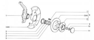
Front suspension: 1 — brake disc; 2 — wheel hub; 3 — hairpin; 4 — lower ball joint; 5 - cap; 6 — housing of the external drive hinge; 7 — adjusting nut; 8 — conical bushing; 9 — hub bearings; 10 — oil seals; 11 — mud ring; 12 — rubber cushion of the stabilizer bar; 13 — clip for attaching the stabilizer bar; 14 — steering knuckle; 15 — body; 16 - stretching; 17 — protective cover of the ball pin; 18 — upper ball joint; 19 — shock absorber rod mounting pads; 20 — upper lever; 21 — cross member; 22 — adjusting washers; 23 — axis of the upper arm; 24 — rubber-metal hinge (silent block) of the upper arm; 25 — rebound buffer; 26 — bracket; 27 - spring; 28 — washers of the lower arm; 29 — axis of the lower arm; 30 — rubber-metal hinge of the lower arm; 31 — lower arm; 32 — lower insulating gasket of the spring; 33 — lower spring support cup; 34 — compression stroke buffer; 35 — shock absorber; 36 — bracket for fastening the stabilizer bar to the body; 37 — rubber cushion of the stabilizer bar; 38 — stabilizer bar.
The ball joints of the upper and lower control arms are interchangeable. The support is attached to the lever with three bolts. The threaded ends of the pins of the upper and lower bearings point downward and fit into the tapered holes of the steering knuckle. The pins are secured with self-locking nuts. Thus, the steering knuckle can rotate about an axis passing through the centers of the spheres of the ball joint pins. The suspension arms, in turn, can rotate on their axes within the range of the rubber-metal hinges. The upper arm axle has two holes and threads on both ends. Bolts pass through the holes, securing the axle to the suspension cross member. Washers are installed on the bolts between the axle and the cross member to adjust the camber angles and the longitudinal inclination of the wheel rotation axis. The threaded ends of the axle fit into the rubber-metal hinges of the lever. There are washers on both sides of each hinge: the smaller one (flat) is on the inside, the larger one (convex outward) is on the outside.
The self-locking nuts of the upper arm axle are finally tightened only with the vehicle loaded, otherwise the hinge will be constantly tightened and quickly fail. The lower arm axle is a bolt that passes through a bushing in the suspension cross member and the rubber-to-metal joints of the arm.
Just like the upper arm joints, each lower arm joint is tightened between two washers, but another thrust washer (thick) adjacent to the bushing and several adjusting washers (thin) are added between the inner washer and the bushing.
The thickness of the washers is selected at the factory; when dismantling the lever, you must remember their number and location. Changing the location of the washers is permissible only if it is necessary to restore the suspension geometry (for example, after an accident, replacing a cross member). In this case, the distance between the outer washer and the flange of the bushing of the rubber-metal hinge after tightening the nut should be in the range of 3.0-7.5 mm. In the event that it is impossible to adjust the longitudinal inclination of the steering axis with working suspension parts, you can move some of the washers from one end of the lever to the other.
The suspension cross member is a curved tubular steel beam, to which forged steel brackets are welded on both sides. In the lower part of the bracket there is a bushing for the lower arm axis, and the upper part is made as a vertical platform with three pairs of holes for mounting bolts. The top pair of bolts secures the upper arm axle to the crossmember. The middle pair of bolts secures the power unit support bracket, the cross member and its bracket. The bracket is attached to the body side member and serves as a support for the upper coil of the spring and the shock absorber rod. The bottom pair of bolts secures the cross member and its bracket. Two brackets for fastening the front axle gearbox are welded to the tubular front part of the cross member. Two brace brackets are welded to the tubular rear of the cross member. Guys are bolted to them, increasing the longitudinal rigidity of the structure. The rear (threaded) end of the brace is attached to the bracket on the car body with two nuts and washers.
When installing the extension, tighten the inner nut until the washer touches the bracket, and the outer nut with the recommended torque. At the bottom, the suspension spring rests on the lower spring support cup through a plastic spacer. A rubber insulating gasket is installed between the upper spring support cup and the cross member bracket. The compression stroke buffer support strut (it faces down) and the rebound buffer cup (it faces up) are welded to the cross member bracket. At maximum suspension travel, the compression stroke buffer rests against the lower spring support cup, and the rebound buffer rests against the boss on the upper arm. The lower spring support cup is attached to the lower arm with four bolts, nuts and spring washers.
The mounting brackets for the lower end of the shock absorber and anti-roll bar (behind the spring) are also welded to the lower cup. A rubber-metal hinge is pressed into the shock absorber eye, so the lower mounting bolt can only be tightened with the car under load. The shock absorber rod is attached to the cross member bracket through two rubber cushions with a nut and washers. The nut can be tightened in any suspension position. The anti-roll bar (bar) is a curved rod made of spring steel. It reduces car roll when cornering. Through rubber pads, pressed by steel clips, the rod is attached at two points to the body and at two points to the brackets on the lower spring support cups. The lower cover of the front axle gearbox is attached to its middle part through rubber cushions. Suspension repair mainly involves replacing worn and damaged parts. Pay special attention to the condition of the protective covers of the ball joints (boots). If the boot is torn, immediately replace it and the lubricant, otherwise the support will quickly fail. Replace silent blocks when rubber bulges, tears, cracks or severe wear.
Information relevant for Chevrolet Niva cars 2009, 2010, 2011, 2012, 2013, 2014, 2020, 2020, 2020, 2020 model year.
Replacing the upper arm
Removing the upper arm
If, when diagnosing the front suspension of a Chevrolet Niva, you find mechanical damage or decide to replace worn silent blocks, you will have to remove the upper arm. To work, you will need two 13mm wrenches, one 22mm wrench, a jack and a wheel wrench. Jack up the car and remove the wheel, then place a support under the lower control arm and load the suspension by lowering the car.
Remove the three nuts that hold the ball joint to the upper arm. Then unscrew a couple of nuts from the upper arm axle bolts. When turning the bolts, they must be held with a wrench.
Remove the upper arm, paying attention to the number and location of the adjustment washers that are installed on the axle mounting bolts. Installation of the upper arm into silent blocks is carried out in the reverse order.
Replacing the silent blocks of the upper arm
Upper arm silent blocks
The silent blocks in the upper lever are changed for the same reasons as in the lower one. To work you will need a 22mm wrench and a puller. First, remove the upper arm with all silent blocks and the machine axle. Unscrew the upper arm nuts and remove the washers and nuts from the axle.
Using a puller, you need to press the silent blocks out of the lugs and press new ones in here. After that, put everything back together and adjust the wheel alignment. You won’t be able to do this on your own, since you probably don’t have special equipment.