The Chevrolet Niva is the product of a joint development of two companies, and the result is a car that is quite comfortable and completely ready for driving on our roads. This amazing synthesis has become very widespread among us and is quite satisfactory for the majority of our consumers. Today we are interested in the braking system of this car, which is designed for off-road driving conditions and the shortest possible braking distance when driving in urban conditions. Let’s figure out what systems are installed here and how the mechanisms differ from others.
General device
Chevrolet Niva combines two subsystems. Each brake system has its own purpose, they are called:
- Working.
- Parking lot.
The purpose of the latter is extremely clear; this braking system ensures that the Chevrolet Niva jeep is held in one position when parked on an uneven surface for a long time. The brake system, called the service brake, is regularly used when the car is moving. With its help, the driver slows down at traffic lights and stops the car where he needs it. You can control its operation using the foot pedal, which is located to the left of the gas pedal and to the right of the clutch, if, of course, there is one.
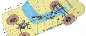
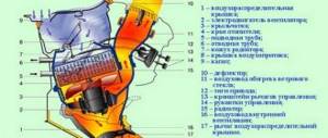
Brake system diagram and maintenance
- rear brake wheel (working) cylinder;
- rear parking brake cable;
- rear cable guide;
- front parking brake cable;
- parking brake lever;
- brake pedal;
- vacuum booster;
- pipeline;
- master cylinder;
- front brake wheel cylinder block;
- master cylinder reservoir;
- pressure regulator;
- pressure regulator drive lever
Checking and adjusting brakes
Checking pipelines and connections
1. To prevent sudden failure of the brake system, carefully check the condition of all pipelines.
- metal pipelines should not have dents, cracks and should be located away from sharp edges that could damage them;
- brake hoses must not have through cracks in the outer shell and must not come into contact with mineral oils and lubricants that dissolve rubber; by pressing the brake pedal firmly, check to see if any swelling appears on the hoses, indicating a malfunction;
- all brake lines must be properly secured; loosening of the fastening leads to vibration, causing breakdowns;
- Liquid leakage through pipeline connections is not allowed; If necessary, tighten the fittings until they are tight without subjecting the pipelines to deformation.
2. Replace parts with new ones if there is the slightest doubt about their suitability.
3. Regardless of their condition, replace flexible hoses with new ones after 100,000 km or after 5 years of vehicle operation to prevent sudden ruptures due to aging.
Principle of operation
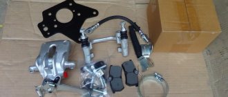
On the Chevrolet Niva, it was decided to use a standard hydraulic drive for the system and a combined mechanism. A disc brake was installed on the front axle, and a drum brake on the rear, as in the classic version of this car. But, unlike the original version of the car, the drive was modified. This brake system received a vacuum booster for the force applied to the pedal and a more advanced master cylinder.
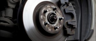
The disc mechanism of a Chevrolet Niva car has two main parts: a disc and a caliper. The disk has a tight engagement with the wheel hub and rotates with it, that is, the disk is a moving element. The caliper is mounted on a special bracket above the disc. Pads and working cylinders are inserted inside it, which press the pads to the disc. The drum has a slightly different design; here the moving part is the drum body itself, which hides wider pads inside. Here, too, the working cylinders press the wider pads against the horizontal plane of the drum. This design has a higher efficiency due to wider and longer pads. In addition, here all the mechanisms are hidden inside the drum and are completely protected from external influences. This is very convenient if the car is often used in off-road conditions.
Brake system Chevrolet Niva
- Repair manuals
- Repair manual for Chevrolet Niva 2002+.
- Brake system
Design Features
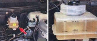
| Rice. 11.5. Main brake cylinder and vacuum booster: 1 – main cylinder; 2 – master cylinder reservoir; 3 – vacuum booster; 4 – locking bracket; 5 – finger |
The vehicle can be equipped with brake master cylinder 1 ( ) with reservoir 2 and vacuum booster 3, used on front-wheel drive VAZ vehicles.
| Rice. 11.6. Device of a vacuum brake booster: 1 – vacuum booster housing; 2 – amplifier housing cup; 3 – rod; 4 – adjusting bolt; 5 – rod seal; 6 – sealing ring of the master cylinder flange; 7 – diaphragm return spring; 8 – amplifier pin; 9 – bushing for fastening the check valve; 10 – check valve; 11 – hose mounting fitting; 12 – diaphragm; 13 – amplifier housing cover; 14 – sealing cover; 15 – piston; 16 – protective cover of the valve body; 17 – air filter; 18 – pusher; 19 – pusher return spring; 20 – valve spring; 21 – valve; 22 – valve body bushing; 23 – rod buffer; 24 – valve body; A – vacuum chamber; B – atmospheric chamber; C, D – channels |
Vacuum booster.
The rubber diaphragm 12 ( ) together with the valve body 24 divides the cavity of the vacuum amplifier into two chambers: vacuum A and atmospheric B. Chamber A is connected to the engine inlet pipe through the check valve of the tip 11 and a hose.
The 24 valve body is plastic. At the outlet of the cover, it is sealed with a corrugated protective cover 16. The valve body contains the main cylinder drive rod 3 with a support sleeve, rod buffer 23, valve body piston 15, valve assembly 21, pusher and valve return springs 19 and 20, air filter 17 , pusher 18.
When you press the pedal, pusher 18 and piston 15 move, followed by valve 21 until it stops against the seat of the valve body. In this case, cameras A and B are separated. As the piston moves further, its seat moves away from the valve and through the resulting gap, chamber B is connected to the atmosphere. The air entering through filter 17, the gap between the piston and the valve and channel D creates pressure on the diaphragm 12. Due to the difference in pressure in chambers A and B, the valve body moves along with the rod 3, which acts on the piston of the main cylinder.
When the pedal is released, valve 21 moves away from the body seat and through the resulting gap and channel C of chambers A and B communicate with each other.
| Rice. 11.7. Brake master cylinder structure: 1 – master cylinder body; 2 – low pressure sealing ring; 3 – drive piston of the left front–right rear brake circuit; 4 – races porn ring; 5 – high pressure sealing ring; 6 – pressure spring of sealing rings; 7 – spring plate; 8 – piston return spring; 9 – washer; 10 – locking screw; 11 – drive piston of the right front–left rear brake circuit; 12 – connecting sleeve; 13 – tank; 14 – brake fluid emergency level sensor; A – gap |
Master cylinder
with a sequential arrangement of pistons ( ). A tank 13 is fixed to the main cylinder body, in the filler plug of which a sensor 14 for emergency brake fluid level is installed. O-rings 5 of the main cylinder and similar rings of the rear wheel cylinder are interchangeable.
Removing and installing a vacuum booster
| 1. Disconnect the block with wires from sensor 14 (see. ) emergency brake fluid level. |
| 2. Unscrew the nuts securing the master cylinder to the amplifier, remove it from the studs and move it to the side, carefully bending the pipelines so as not to damage them. |
| NOTE When removing the booster, do not disconnect the main cylinder of the hydraulic brake drive from the hydraulic system so that air does not get into it. |
| 3. Disconnect the hose from the booster check valve. |
| 4. Disconnect the vacuum booster from the brake pedal by removing the locking bracket 4 (see. ) and removing finger 5. |
| 5. Unscrew the nuts securing the vacuum booster to the brake pedal bracket and the body. |
| 6. Remove the vacuum booster. |
| 7. Install the vacuum booster in the reverse order of removal. |
| WARNING The brake booster is a critical component that directly affects traffic safety. Repairing an amplifier requires special installation and monitoring equipment and requires highly qualified performers. Therefore, do not disassemble the faulty amplifier, but replace it with a new one. |
Removing and installing the master cylinder
The master cylinder is removed from the vehicle for replacement or repair. However, if the contractor does not have the skills to perform disassembly and assembly work, reassembling the master cylinder often does not lead to the desired results, so we recommend replacing the faulty cylinder assembly.
| 1. Use a rubber bulb to pump out the liquid from the tank. |
| 2. Disconnect the lines from the master cylinder. |
| NOTE Seal the holes at the pipes and at the master cylinder to prevent fluid leakage and dust and dirt from entering them. |
| 3. Disconnect the block with wires from the terminals of the emergency brake fluid level sensor. |
| 4. Unscrew the two nuts securing the cylinder to the vacuum booster and carefully remove the cylinder and reservoir assembly from the studs. |
| 5. Unscrew the filler cap and drain the remaining brake fluid from the reservoir and cylinder. |
| NOTE If you have removed the reservoir from the master cylinder, inspect the rubber bushings that secure the reservoir. Replace bushings that are torn, cracked or have lost elasticity. |
| 6. Install the master cylinder, tighten the nuts securing it and fill the brake fluid into the reservoir. Place a container or rag under the master cylinder to catch the brake fluid. |
| 7. Close the holes for the brake pipes in the master cylinder with your fingers. An assistant should slowly press the brake pedal until brake fluid . |
| 8. At this moment, connect the tubes to the front holes of the cylinder and tighten the nuts securing them. In this case, the assistant must keep the pedal pressed. Connect the tubes to the rear holes of the cylinder in the same way. Install all removed parts in reverse order. Press the brake pedal and, if it is “soft”, bleed the brake system (see section 8 “Brake system”, “Bleeding the brake system hydraulic drive”). |
Dismantling and assembling the master cylinder
| 1. Remove the master cylinder from the vehicle (see “Removing and installing the master cylinder”). |
| 2. Using a wooden spatula as a lever, remove tank 13 (see Fig. ) from the cylinder. |
| 3. Remove connecting sleeves 12 from the main cylinder body. |
| Rice. 11.8. Parts of the master cylinder: 1 – cylinder body; 2 – low pressure sealing ring; 3 – drive piston of the left front-right rear brake circuit; 4 – spacer ring; 5 – high pressure sealing ring; 6 – pressure spring of the sealing ring; 7 – spring plate; 8 – piston return spring; 9 – washer; 10 – locking screw; 11 – drive piston of the right front–left rear brake circuit; 12 – sealing gasket |
| 4. Remove two locking screws 10 ( ) |
| 5. By hand, remove the pistons of the first and second chambers with cuffs, washers and springs from the body. In this case, the piston 11 of the second chamber may not come out freely. To remove it with the remaining parts, hit the end of the body from the side of the first chamber on a clean board and push it through the first chamber. To remove the piston, you can also use compressed air, which must be supplied to the outlet of the second chamber, while closing the hole under the tank. |
| 6. Carefully inspect and make sure that bore and the working surface of the pistons are completely clean, and that there is no rust, marks or other irregularities. Otherwise, replace the parts with new ones. |
| 7. Replace cuffs that are torn, swollen, or have lost elasticity. It is recommended to replace the seals with new ones each time the master cylinder is disassembled, regardless of their condition. |
| 8. Check the elasticity of the piston springs, the length of which should be under a load of 38.26–46.1 N (3.9–4.7 kgf) - 41 mm, under a load of 81.81–99.47 N (8.34– 10.14 kgf) - 21 mm, in a free state - 59.7 mm. Replace springs that have lost their elasticity. |
| 9. Gaskets 12 (see ) under the locking screws, it is recommended to replace them with new ones. |
| 10. Before assembly, wash all parts with clean brake fluid. Do not allow parts to come into contact with mineral oils, gasoline or diesel fuel, as even residual traces of these liquids can lead to destruction of the rubber seals. |
| 11. Reassemble the cylinder in the reverse order of disassembly. In this case, lubricate all parts with brake fluid. |
↓ Comments ↓
1. Car structure
1.0 Car structure 1.1 General information about cars 1.2 Passport data 1.3 Car keys 1.4 Controls 1.5 Heating and ventilation 1.6 Doors 1.7 Seat belts 1.8 Adjusting the position of the front seats 1.9 Adjusting the steering wheel
2. Recommendations for use
2.0 Recommendations for operation 2.1 Safety rules and recommendations 2.2 Tools and accessories 2.3 Running in the car 2.4 Operating the car during the warranty period 2.5 Checking the car before leaving 2.6 Replacing the air filter entering the cabin 2.7 Using a jack 2.8 Towing the car
3. Problems along the way
3.0 Malfunctions along the way 3.1 The engine does not start 3.2 Malfunctions of the fuel injection system 3.3 No idle speed 3.4 Interruptions in engine operation 3.5 The car moves jerkily 3.6 The car accelerates poorly 3.7 The engine stalls while driving 3.8 The oil pressure has dropped
4. Engine
engine piston of the fourth cylinder to the TDC position of the compression stroke
5. Transmission
5.0 Transmission 5.1 Clutch 5.2 Possible malfunctions of the clutch, their causes and solutions 5.3 Gearbox 5.4 Possible malfunctions of the gearbox, their causes and solutions 5.5 Transfer case 5.6 Possible malfunctions of the transfer case, their causes and solutions 5.7 Driveshaft 5.8 Possible malfunctions of the driveshaft , their causes and solutions 5.9 Front wheel drives
6. Chassis
6.0 Chassis 6.1 Front suspension 6.2 Possible malfunctions of the front suspension, their causes and solutions 6.3 Rear suspension 6.4 Possible malfunctions of the rear suspension, their causes and solutions 6.5 Shock absorbers
7. Steering
7.0 Steering 7.1 Design features 7.2 Inspecting and checking the steering on the vehicle 7.3 Checking the tension and adjusting the power steering pump drive belt 7.4 Replacing the fluid in the power steering hydraulic system 7.5 Replacing the power steering hydraulic system reservoir 7.6 Bleeding the power steering system 7.7 Adjusting the gap in the roller engagement with worm 7.8 Removing and installing the steering wheel 7.9 Replacing steering shafts
8. Brake system
8.0 Brake system 8.1 Device features 8.2 Useful tips 8.3 Checking and adjusting the brake system 8.4 Replacing brake fluid 8.5 Bleeding the hydraulic brake system 8.6 Master brake cylinder 8.7 Vacuum brake booster 8.8 Pressure regulator 8.9 Replacing hoses and pipelines of the hydraulic brake system
9. Electrical equipment
9.0 Electrical equipment 9.1 Design features 9.2 Fuses and relays 9.3 Generator 9.4 Possible generator malfunctions, their causes and solutions 9.5 Starter 9.6 Possible starter malfunctions, their causes and solutions 9.7 Ignition switch (lock) 9.8 Replacement and maintenance of spark plugs 9.9 Engine control system
10. Body
10.0 Body 10.1 Design features 10.2 Removing and installing front fender liners 10.3 Removing and installing front fenders 10.4 Removing and installing decorative trims on the front fenders and doors 10.5 Replacing buffers 10.6 Removing and installing radiator trim 10.7 Removing and installing the hood 10.8 Removing, installing and adjusting the lock and hood lock drive 10.9 Tailgate
11. Vehicle options
11.0 Vehicle options 11.1 Clutch release master cylinder 11.2 Electromechanical power steering 11.3 Brake system
12. Car care
12.0 Car care 12.1 Checking the car before leaving 12.2 Washing the car
13. Purchase of spare parts
13.0 Purchasing spare parts 13.1 Engine oil 13.2 Greases 13.3 Coolants 13.4 Brake fluid
14. A trip to the service station
14.0 A trip to the service station 14.1 Useful tips
15. Winter operation of the car
15.0 Winter operation of a car 15.1 How to prepare a car for winter 15.2 Recommendations for starting the engine in severe frost 15.3 What is useful to buy for winter 15.4 Useful winter tips
16. Preparation for technical inspection
16.0 Preparation for technical inspection 16.1 Recommendations 16.2 List of malfunctions and conditions under which the operation of vehicles is prohibited 16.3 Changes to state standards regulating the maximum permissible content of harmful substances in the exhaust gases of vehicles 16.4 Standard form of diagnostic card for instrumental control points
17. Applications
17.0 Appendix 17.1 Appendix 1. Tightening torques for threaded connections 17.2 Appendix 2. Basic data for adjustments and control 17.3 Appendix 3. Fuels and lubricants and operating fluids 17.4 Appendix 4. Filling volumes 17.5 Appendix 5. Lamps used on vehicles 17.6 Appendix 6. 17.7 Appendix 7.