Device and features
The plant equips cars with synchronous generators Iskra, Pramo Electro or BATE, equipped with a silicon rectifier unit and an automatic voltage corrector. A pulley is installed on the rotor shaft, which is secured with a key and a nut. Torque is transmitted from the engine crankshaft using a belt drive with a manual tension mechanism.
When adjusting, you should follow the manufacturer's recommendations, since excessive tension leads to premature failure of the bearing supports.
The diode rectifier unit is removable, which simplifies the equipment repair procedure. The straightening device is hermetically sealed, i.e., it is ensured that it remains operational when water enters. The rated output voltage is 14 V, the current does not exceed 80-90 A (on cars with air conditioning, the parameter is increased to 110-120 A).
The rotor is mounted on 2 ball bearings and rotates to the right (as viewed from the drive side). The external casing of the generator is made of aluminum alloy, and a fan is provided for cooling.
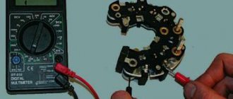
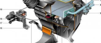
Diode bridge
A semiconductor diode bridge mounted on the outer part of the back cover of the electric generator is designed to convert alternating current into direct current. The design of the unit uses silicon diodes, which allow voltage to be conducted in only one direction.
To prevent short circuits, the parts are located in a sealed casing. During operation, the device is cooled by convection and air flow created by a fan mounted on the rotor.
Semiconductor diode bridge for UAZ Patriot.
Three-level regulator
The factory-assembled generator design uses a standard rectifier unit, which operates without taking into account the ambient temperature. As a result, there is a voltage drop and incomplete charging of the battery.
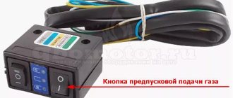
To increase the operating parameters of the electric generator, a modernized 3-level regulator is used. The device automatically adjusts the current parameters in the generator output circuit, focusing on the air temperature. The design includes a mechanical toggle switch to switch to winter operation mode.
Patriot vehicles do not charge the battery due to the alternator rotor speed decreasing when driving off-road (putting additional load on the electrical circuits).
The situation is corrected by replacing the pulley (to increase the rotor speed) or installing a more powerful generator produced by alternative suppliers. The use of a 3-level regulator allows you to improve the operation of the electric generator; installation of an additional device is carried out independently.
What is included in the electrical circuit?
What features do automotive electrics have on old cars produced by the Ulyanovsk Automobile Plant?
Electronic components
The electrical circuit of the UAZ 452 itself is quite simple - single-wire.
By its design, the wiring diagram of a UAZ390995 or other model is characterized by the following solutions:
- The vehicle body is used as the mass.
- Any electrical equipment of the old-style circuit on a UAZ 409 or other model, as well as actuators, are equipped with a negative terminal, which is connected to the car body. According to experts, in general this scheme is imperfect.
According to the operating instructions for electrical equipment, the driver must periodically diagnose the condition of the integrity of the contacts. We are also talking about their oxidation. If the driver notices the presence of oxidation on the terminals, he should treat them using fine-grained sandpaper.
Engine compartment
In this case, the engine compartment is located directly in the passenger compartment in accordance with the design of the car.
Access to the electrical circuit and other mechanisms and assemblies is made from the interior, as a result of dismantling the cover, which:
- Designed to protect the motorist and passenger from exhaust gases entering the cabin.
- Allows you to protect the car interior from the penetration of dirt and dust.
- Performs the function of an additional heating device, in particular passively, as a result of heating.
Engine compartment of an AUZ car
Previously, the UAZ 396255 and other models with a carburetor used an engine from the legendary Pobeda, which was later replaced with a more improved and modern unit. In particular, it means a Volga engine. This decision at one time, back in 1964, was facilitated by the serial launch of a production line at the ZMZ enterprise. Despite the fact that many domestic car enthusiasts claim that the UAZ 390994 injector circuit in the engine compartment is located in an inconvenient place due to the lack of a hood, this is not so. Decades of operation have proven that the absence of a hood in no way affects the diagnosis and maintenance of the car.
Passive safety
The very design of the domestic Loaf with the absence of a hood at first raised many questions in terms of the safety of the driver and passengers. As a result of several dozen crash tests that were carried out back in the early 70s of the last century, it was revealed that the car is no less safe when compared with other domestic cars. As the results showed, in the event of an accident, both the driver and passengers of the car have a good chance of avoiding injury in an accident.
Removing the generator
Algorithm for removing the generator from Patriot cars with a ZMZ 409 gasoline engine:
Step-by-step removal of the generator from a UAZ Patriot.
- Disconnect the negative cable from the battery.
- Disconnect the plug with cables connected to the field windings.
- Unscrew the nut securing the wire to the positive terminal of the electric generator.
- Loosen the tension roller by turning the roller mounting bolt, and then rotate the screw that reduces the tension of the belt drive.
- Remove the belt from the pulleys, and then unscrew the generator housing locking bolt.
- Unscrew the nut designed to secure the upper part of the device to the adapter bracket.
- By analogy, the lower attachment point is unscrewed and the fixing bolt is removed from the hole.
- Disconnect the bracket from the cylinder block (secured with 2 nuts) and dismantle the generator for repair or maintenance.
On cars with a 4CT90-1 diesel engine (Andoria), a single belt is used to drive the generator, rotating a fan pulley connected to the water pump rotor. Before dismantling the electric generator, you will need to remove the impeller, which prevents the removal of the belt and blocks access to the bolts.
Additionally, the air pipes are removed, blocking access to the generator. The generator housing is used to tension the belt, the adjusting bolt is located at the top, and an additional support is mounted at the bottom.
troubleshooting
On any domestic car, problems periodically arise in the operation of electrical equipment. If you notice that the UAZ wiring is not working correctly, you need to diagnose it and check all the elements. If there are any malfunctions in the operation of electronic devices, first of all you need to check whether the fuses in the mounting block have burned out. If everything is fine with these elements, but the equipment still does not function, for example, if we talk about optics, then you need to check whether the light bulbs are working. If the lamps themselves are working, it is necessary to ring the electrical part using a tester (the author of the video about ringing is Ramil Abdullin).
If the Loaf refuses to start at all, you need to do the following:
- First of all, check the functionality of the battery.
- With the battery charged, use a tester to test the circuit from the coil to the generator; often the reason for the inability to start the engine is breaks in the wiring. If there are breaks, the wires should be changed. If there is oxidation on the contacts, they should be cleaned.
- Starting the power unit will be impossible if there is no spark. To diagnose the presence of a spark, remove the high-voltage cable from the spark plug and bring it to the body. When you try to start the engine, a spark should jump between the cable and the body.
- If there is no spark, the problem may be carbon deposits and deposits on it. By the way, carbon deposits are often the cause of unstable engine operation and tripping. To get rid of such a malfunction, it is advisable to clean the spark plugs; step-by-step instructions for this process are presented.
The main command vehicle of the armed forces - this is how the UAZ 469 SUV can be described. And indeed, having replaced the GAZ-69 in 1972, it secured this honorable duty for many years, proving the correctness of the design and main components with its endurance and reliability.
Traditionally, the UAZ 469 was produced in two versions:
- Cargo-passenger version – 7 seats and 100 kg of luggage;
- Commander version - 2 seats for passengers and 600 kg of luggage.
For reference: regardless of the version, the UAZ 469 can tow a trailer with a total weight of 850 kg.
Industry standard 1945
According to the old vehicle classification system, in force since 1945, the UAZ 469 was produced under this name, using an alphanumeric name:
- The letter abbreviation UAZ stood for Ulyanovsk Automobile Plant;
- 469 is a serial factory index assigned by the enterprise itself to its models and developments.
For reference: according to the industry standard of 1945, each automobile plant was assigned a specific numbering. For MZMA, which produced Moskvich 408 and 412, these are numbers from 400 to 449, for the Ulyanovsk Automobile Plant these are numbers from 450 to 484, etc.
1966 Industry Standard
Although at the time of the release of the UAZ 469 (1972) a new industry classification system was adopted (industry standard OH 025270-66), the car plant continued to use the name according to the old standard.
However, in 1985, the automaker was forced to change its name in accordance with current requirements:
- the car was assigned a four-digit number - 3151;
- According to the new system, the car can be called in the documentation as UAZ 3151.
For reference: industry standard OH 025270-66 prescribes determining the type of vehicle by engine displacement, length and weight. The first digit indicates the class of the car, the second – the type (truck or passenger car), the third and fourth – the factory model index.
The car plant named all further modifications and new models in accordance with current standards. In particular, the UAZ Patriot, which appeared in 2005, according to the industry classification, received the “correct” designation - UAZ-3163. For greater identification, the factory instructions contained both names.
Installation of a three-level regulator
Algorithm for installing equipment on UAZ Patriot gasoline and diesel engines:
- Dismantle the generator, and then remove the protective casing located on the rear cover.
- Disconnect the standard voltage regulator and inspect the condition of the collector plates on the generator rotor.
- Install the upgraded unit into place, which is secured and connected with standard nuts and wires.
- Route the additional cable with corrugated protection through the additional hole in the protective cover.
- Install the control controller on the wall of the engine shield. Enable the operating mode appropriate for the operating conditions.
- Install the generator in its original place.
It should be borne in mind that the use of a 3-level regulator is not a panacea. It is not recommended to connect additional electrical devices to a vehicle with the engine running at idle speed.
To power external equipment, it is recommended to use portable gas generators equipped with rectifier units.
Connection diagram
The regulator body is connected to the car body, the plug with the letter Ш is used to connect to the modernized brush assembly. The second output from the brushes goes to the third contact B of the regulator. Block B is connected to the positive pole of the battery through a relay operating from the ignition switch.
A resistor is installed in the instrument panel so that the indicator does not show errors at idle speed.
Period from 1965 to 1984
During this period, the automaker equipped its products with electrical components available to the domestic industry. Some of them were known for a long time, others were experimental, as evidenced by videos from previous years, and which had to prove their suitability.
Lighting control
In particular, the controls and a number of main units migrated from its predecessor, the GAZ-69. Thanks to this, the price of the car remained the same.
On models of the first years of production, a foot light switch was installed, which had several operating modes:
- The first position activated the circuit for switching the low beam headlights and side lights;
- In the second position, the low and high beam headlight circuit was activated.
For reference: Turning on the headlights (low or high beam) led to the turning off of the front side lights.
The modernized light switch has a different operating algorithm:
- The first position supplies power to the side lights only;
- The second position is side lights and low (high) beam headlights.
Caution: This algorithm with non-switchable dimensions is a mandatory requirement for passing MOT. The factory instructions give recommendations for reworking the old circuit, in which it is important not to mix up the contacts of the foot switch.
The most correct option is to replace the old switch with a modern one, which uses only 3 contact groups.
Also, on older versions of the “452” there was no alarm, so in the electrical diagram:
- An RS-57 breaker relay was installed (mounted in the wiring gap from the “+” terminal of the battery to the direction indicator switch);
- The middle contact of the relay closed the indicator light on the instrument panel.
Ignition system
Also on the “452” contact ignition was installed:
- The “+” wire from the battery supplied power to the ignition coil;
- From the coil, the high-voltage wire transmitted the impulse to the breaker (distributor) and further to the spark plugs.
The operation of electrical equipment in any modern car directly depends on the performance and integrity of the wiring. That is why every car owner should understand. In particular, we are talking about the legendary domestic UAZ cars. What the electrical circuit of the old-style UAZ-3303 is and what malfunctions are typical for it - we will talk about this below.
[Hide]
Generator bearing
The generator rotor is mounted on 2 ball bearings located in the end caps. The bearings are equipped with protective washers to prevent dirt from entering the treadmills and to retain lubricant. When the elements wear out, the rotor wobbles and noise occurs during rotation.
To carry out repairs, the electric machine is removed from the motor and then disassembled. Worn bearings are pulled together with a screw puller. New parts are pressed in using mandrels; it is recommended to check the amount of lubricant under the protective covers.
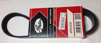
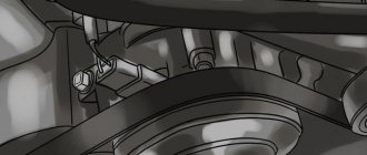
Belt replacement
To drive the generator rotor, a poly-V-belt is used, which has a limited service life. The unit must be replaced during routine maintenance or when cracks appear on the inner surface. To access the belt drive, you will need to remove the plastic diffuser and the viscous fan.
Then the tension roller is loosened with a wrench and the old belt is removed from the pulley. After installing the new part, the correctness of the branches is checked, and a roller is used to adjust the tension.
Electrical wiring components for UAZ 469, UAZ 390945 and other models
The electrical circuit of the UAZ 3151 4 includes 69 positions; it is possible to additionally connect special fog lights, but the installation of a switch type 343.01.03 is required. It will be mounted directly on the dashboard in a convenient location. The general wiring diagram of a machine includes an extensive list of different devices.
This is a front light, headlights that are easy to replace if necessary. An audio signal is also connected to the general system. Further, the UAZ wiring diagram includes a special fuse and additional resistance. The circuit has a connection to the side direction indicators, and a switch for the heater is located right there.
The wiring supplies the generator, there are connection points for the light that illuminates the engine compartment, and outputs for the heater fan motor. Modern UAZ electrical wiring includes spark plugs powered by it. A relay is installed for indicators; it is used to ensure the operation of emergency and turn signals.
The electrical circuit has outputs to a coil, a starter relay, there is a special sensor-distributor, and a switch. In one area there are the following points: turn off the masses, hazard warning lights, battery, electric washer. There is a separate connection for the fuse box and the following sensors:
- emergency pressure for oil;
- fuel readings;
- for oil pressure indicator;
- overheating of used coolers;
- temperatures of the coolers used;
- determining the brake fluid level.
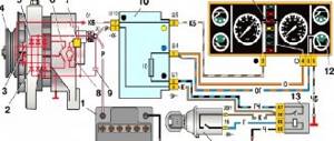
1.Low voltage ignition coil; 2.Transistor electronic switch; 3. Sensor-distributor (distributor); 4.Electric spark plugs; 5.Fuse block; 6.Emergency breaker; 7.Additional electrical resistance.
The electrical diagram includes connection points for the starter, speedometer, windshield wiper and relay for it, EPH unit, voltmeter. There are the following components:
- relay for car headlights;
- sockets used to power portable lamps;
- parking brake switches, braking systems.
For electrical equipment of UAZ 31512(14) or UAZ 390945, the following switches are installed:
- for brake signal;
- for parking brake;
- alarm;
- interior light lamps;
- sound signal;
- rear fog lamp;
- ignition;
- reverse lights.