Any car has its own on-board autonomous electrical network with all the inherent elements, energy source, storage device and consumers. Each of the nodes is functionally complete, they are connected by electrical wiring, and the network parameters are clearly standardized thanks to the accumulated experience in the production of automotive electrical equipment.
The power source for the electronics is a generator, which will be discussed in this article.
Kinds
There are two main types of car generators:
- Direct current, a voltage of a certain polarity is generated directly on the windings;
- Alternating current, since a constant voltage is still required, the generator is equipped with an internal semiconductor rectifier.
Currently, only the second type is used, since it has undeniable advantages, and its windings produce three-phase voltage, which is easier to smooth out ripples and allows more efficient use of the weight and size of the device.
We will look at what is inside this device below.
Device
Externally, all generators are similar at first glance, but those who are familiar with electrical engineering can easily determine which device they are dealing with. The situation is simplified by the fact that DC machines were used only on very relic cars, long out of production.
DC generator
The DC dynamo includes:
- frame;
- field windings on a stator fixedly fixed in the housing;
- power windings on a rotating armature;
- brush assembly with copper-graphite or carbon brushes that remove current from the rotating armature commutator;
- a voltage regulator that stabilizes the output by regulating the excitation current in the stator electromagnet windings;
- drive pulley on the armature shaft;
- bearings in which the armature shaft rotates.
To create acceptable output power, the entire unit had to be massive and metal-intensive, so with the advent of high-quality rectifier semiconductor devices, DC generators were no longer used in cars.
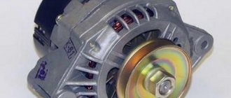
Alternator
In principle, it is designed similarly, but the output power is generated by multiphase stator windings, made of thick wire and not requiring powerful and unreliable current collectors.
The composition of the equipment is also similar:
- housing with mounting brackets and electrical terminals;
- stator windings installed in the housing can be removed when its halves are disconnected;
- rotor with soft electrical iron poles, copper windings and commutator;
- brush assembly, where a pair of carbon brushes is usually installed and an integrated semiconductor voltage regulator is built in, through which excitation power is supplied to the brushes;
- a rectifier block, where a three-phase bridge of six power valves (diodes) and three relatively low-power additional diodes for powering the field winding is located; the number of diodes may differ in specifically designed modern designs;
- bearings on the rotor shaft;
- output connectors, power and control, the second power contact is the metal housing of the generator;
- drive pulley and forced cooling impeller.
The entire structure is attached to the front of the engine for convenient organization of belt drive from the crankshaft pulley. Often, by deflecting the generator to the side, the belt tension is adjusted in cases where the more complex design of the drive of mounted units does not imply the presence of a separate tensioner with a roller.
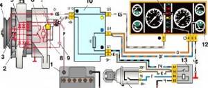
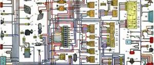
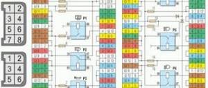
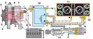
When repairing a VAZ 2107 car generator, you will need this generator set diagram and a detailed current path in the field winding circuit.
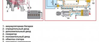
1. Battery. 2, 5. Basic rectifier semiconductor diodes. 6. Generator stator winding coils. 7. Semiconductor integrated voltage regulator (charging relay). 8. Excitation winding (rotor) of the generator. 9. Noise filtering capacitor. 10. Mounting block (relays and fuses). 11. “Battery charging” indicator lamp. 12. Voltmeter (on-board voltage indicator). 13. Ignition relay (ignition switch relay). 14. Ignition switch.
Current path of the excitation winding with the ignition on and the engine not running: Terminal “+” of the battery – pink wire – terminal “30” of the generator – pink wire – contact “1” of connector “Ш10” of the mounting block – internal current-carrying tracks of the mounting block – contact “4” » connector “w1” of the mounting block – brown wire – pin “30” of the ignition relay (installed under the dashboard) – closed contacts of the ignition relay – pin “87” of the ignition relay – black and blue wire – pin “6” of connector “w1” of the mounting block – fuse “pr 10” of the mounting block – contact “1” of connector “w 4” of the mounting block – orange wire – contact “4” of the instrument panel connector (black) – conductors and conductive tracks of the instrument panel – contacts of the “battery charging” warning lamp holder - filament of the "battery charging" lamp - socket contacts - instrument panel conductive tracks - contact "2" of the instrument panel connector (white) - white-brown wire - contact "3" of the mounting block connector "w5" - internal conductive tracks of the mounting block - contact “7” connector “Ш10” of the mounting block – white-brown wire – terminal “61” of the generator – connecting bus for additional rectifier diodes – short conductor – charging relay terminal – internal semiconductor junctions of the charging relay – first brush – first contact ring of the rotor – generator excitation winding – the second contact ring of the rotor – the second brush – the “minus” contact – car body parts – the “-” terminal of the battery.
After starting the engine, a positive potential appears at the point “connecting bus of additional rectifier diodes”, current flows from it further to the brushes. The control lamp is shunted (shorted) by open additional diodes and goes out.
Read, it may come in handy: How to replace the mass air flow sensor on the “seven”
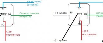
Connection diagram
The circuit is divided into power and control circuits. The powerful output of the generator is connected directly to the positive terminal of the battery through a power connector made of a large cross-section wire secured with a nut on a stud.
The thin control wire is most often simply connected to the ignition circuit through a control light. There are also other schemes when the light bulb has its own control from a specially designed contact on the body.
Principle of operation
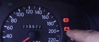
Before starting work, the ignition is turned on in the car, and voltage is supplied to the control contact of the generator through the light bulb. Since the generator is not generating energy at this moment, there is no voltage at the contact, and the light bulb is at battery potential. The indicator lights up and the initial current flows through the field winding.
After the motor starts, the rotating field of the excitation winding on the rotor creates a response induction in the stator windings and the generator begins to generate electricity. Additional diodes raise the voltage at the contact of the light bulb, there is no drop across it, and it stops lighting, signaling that everything is in order, the generator is working.
An electronic circuit in the brush assembly relay-regulator monitors the output voltage, increasing or decreasing the excitation current, thus maintaining the output at a given level, usually 14-15 volts, depending on the type of battery used and its temperature.
The battery at this voltage stops delivering current and goes into charge or hold mode, acting as an additional filter element, since the generator voltage pulsates with the frequency of a three-phase rectifier.
If many consumers are turned on and the engine speed is low, the device is not able to deliver the required power, the voltage decreases, and some consumers begin to be powered by the battery.
When you add speed, the generator increases power, powers consumers, and the excess goes to charge the battery. If the battery is charged and there is excess power, the relay-regulator reduces the excitation current to prevent a dangerous increase in voltage in the network.
Connection diagram for generator in VAZ cars
Industrial models are able to work for a long time, as they are equipped with liquid cooling. When the ignition is turned on, the lamp should be on, and after starting the engine, it should go out if the generator is working. An example is the case of heavy snowfall.
Disconnect the battery. Contents [Hide] Design and principle of operation As you know, the main purpose of a generator device is to convert mechanical energy into electrical energy.
It can be carried out using a special control lamp and a voltmeter on the instrument panel. It is important to compose it correctly and protect the generator itself and consumers from high loads.
The first thing you should talk about is how it is prohibited to connect the generator to your home network. If there is a loss of electricity in the network, you need to start the generator by leaving its ignition switch in the “off” position, the light from the power plant will come on in the house again. For tuning, installations with an output current of amperes and higher are used. All you need to connect is to connect the input cores and consumer buses to the switching devices, and also connect the secondary terminal block to additional generator equipment using a four or five core wire. Afterwards, instead of the control lamp, they began to install a voltmeter, which more or less accurately shows the battery charge level. The rod is driven almost its entire length into the soil.
A simple way to organize automatic switching In order not to manually switch the switch every time there is no electricity supply from the main power supply line of the household, you can make a fairly simple circuit that allows you to automatically switch from an external network to an autonomous one after starting the gas generator. ATS for 2 inputs and a generator. Automatic reserve entry. AVR-02
Basic faults
The manifestation of malfunctions is the voltage in the network leaving the specified limits, as well as extraneous sounds from the operating generator.
The reasons may be different:
- wear of the brush assembly, it is replaced together with the integral relay;
- deep wear of the commutator with brushes, if it can no longer be eliminated by grinding, replace the slip rings or the armature assembly;
- failure of the armature bearings; they can be easily replaced after complete or partial disassembly of the generator;
- burnout of rectifier diodes, currently they are not replaced individually, the entire diode bridge must be replaced;
- short interturn short circuits or breaks in the armature or stator, the corresponding parts are changed;
- burnt or corroded contacts, they can also be replaced or cleaned.
Not directly related to the generator, but a common malfunction is a strong whistle when adding engine speed. This indicates that the belt is slipping on the drive pulleys; the tension can be adjusted, but it is better to replace the belt.
When removing the generator for repair, it is advisable to immediately change the diode bridge, bearings and relay regulator with brushes. This way, the repaired device will gain the highest possible reliability, although only a new generator from a reputable manufacturer can provide a full guarantee.
The device of a car generator
The autogenerator includes several components:
- Rotor.
- Stator.
- Brush block.
- Voltage regulator.
- Rectifier block (diode bridge).
1 - rear bearing; 2 - rectifier block; 3 - slip rings; 4 - brush; 5 — brush holder; 6 - casing; 7 - diode; 8 — bearing sleeve; 9 - screw; 10 — back cover; 11 — impeller; 12 - screw; 13 - rotor; 14 — rotor winding; 15 — front cover; 16 — rotor shaft; 17 — washer; 18 - nut; 19 — pulley; 20 — front bearing; 21 — rotor winding; 22 - stator.
Rotor
A rotor (from the English rotation) is the moving part of a self-generator. It consists of a shaft with an excitation winding located on it, located between two pole halves. The latter are made by stamping, each of them has six beak-shaped protrusions located on top of the winding. These halves form a pole system and slip rings. The purpose of the rings is to supply electric current to the winding through its terminals.
The excitation winding is designed to create a magnetic field. To solve this problem, a weak electric current must be applied to it. Before starting the power unit, the battery supplies current to form a magnetic field. When the internal combustion engine is running and the speed reaches the required value, the generator will supply current to the excitation winding
In addition, the rotor contains:
- Drive pulley.
- Rolling bearings.
- Cooling device (fan).
We recommend: Antifreeze G13: is it necessary to switch to it from G12+?
The rotor is located inside the stator, sandwiched between the housing covers. The covers are equipped with seats in which rotor bearings are placed. In addition, the cover located on the drive pulley side has holes for ventilation.
Generator ventilation diagram
Stator
This element, unlike the one described above, is motionless (static), which is why it got its name. Its task is to obtain an electric current of variable magnitude arising under the influence of the magnetic field of the rotor. The stator consists of windings and a core. The latter is made of sheet steel and has grooves for laying three windings (according to the number of phases). Windings can be laid in one of two ways: loop or wave. The pattern of their connection can also be different - in the shape of a star or a triangle.
1 - core; 2 - winding; 3 - groove wedge; 4 - groove; 5 - terminal for connection to the rectifier.
In a star connection, all the windings are connected together at one end at a common point. Their second ends serve as conclusions. The “triangle” circuit involves connecting the windings according to a different principle: the 1st to the 2nd, the 2nd to the 3rd, and the 3rd, in turn, to the 1st. In this case, the function of the terminals is performed by the connection points. Both diagrams are clearly shown in the figure.
Star and delta circuit
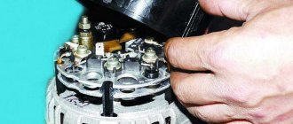
Brush block
The task of this component of the generator is to transmit electricity to the excitation winding. Structurally, the block is a housing with a pair of spring-loaded graphite brushes located in it. The latter are pressed against the slip rings with the help of springs, but are not rigidly fastened to them.
Voltage regulator
The regulator is needed in order to maintain the output voltage within the established limits. This is necessary because the amount of current, as well as its parameters, depends on the engine speed, and the durability of the battery is directly related to the applied potential difference. Insufficient voltage will lead to a “chronic” undercharging of the battery, and excess voltage will lead to overcharging. In both the first and second cases, the battery life will noticeably decrease. Modern cars are equipped with electronic semiconductor regulators.
Voltage regulator
Diode bridge (rectifier block)
The task of this element is to convert the alternating current supplied to it into the direct current necessary to power the on-board network. Structurally, it consists of heat-removing plates, into which 6 diodes are mounted - 2 for each stator winding (on “+” and on “-”).
How to check a car alternator
Ideally, the generator should be checked on a stand, where it will be spun up to rated speed and loaded to maximum, with the power output in this mode checked.
But you can approximately check it without removing it from the car.
- A digital voltmeter (for example, as part of a multimeter) is connected to the output terminal of the generator.
- The engine starts. The voltmeter readings should increase to the nominal 14 - 14.5 volts. The exception will be the case when the battery is very discharged, then the voltage will increase gradually as it charges.
- The engine is brought to medium or high speed, and the car's headlights and other powerful consumers are turned on, the total demand not exceeding the full power of the generator. The voltage should remain stable, which means the generator is delivering its required power.
- The generator should not emit the characteristic howling sounds of worn bearings. If in doubt, simply remove the belt and turn the pulley by hand. The rotor must rotate absolutely smoothly, without vibrations or backlash.
The new generator is very reliable and the first problems may arise only after a run of 100-150 thousand kilometers. But often these devices last much longer, especially with intermediate replacement of the brush assembly.