Where is the signal located on a VAZ-2107 car?
The domestic automaker is releasing to the market several modifications of the VAZ-2107 car model, which is beloved by consumers. The design and location of each of them has a number of its own features:
- in some versions of the car, only one sound signal is used, which is mounted immediately behind the front lining of the cooling radiator. In this case, you can easily reach the part and replace it if the need arises;
- A number of modifications are equipped with two sound signals at once. They are installed directly behind the radiator and have different tones, which makes it possible to quite loudly warn pedestrians and drivers of other cars about the possible danger of a collision.
The RS-528 sound signal relay is mounted in the mounting block of both machines, which is often one of the main causes of breakdowns of this part.
In addition, the circuit can include fuse F7, which prevents the supply of excessively high voltage and its surges, as well as a button located directly on the steering wheel.
What to do if the sound signal on the VAZ 2106 does not work
A non-functioning horn on a car is a very dangerous malfunction. The most unpleasant thing is that they find out about this breakdown just when the signal is needed most - in a dangerous situation on the road. What could cause the signal to fail?
Such a malfunction as a non-functioning sound signal on VAZ 2106 and VAZ 2114 cars is very easy to diagnose and repair in the process, just study the connection diagram and follow the instructions that you will receive after reading the article to the end.
Repair of contact distributor
It is better to repair the distributor-distributor or diagnose it after first removing the device from the engine. Firstly, it will be much more convenient, and secondly, you will have the opportunity to assess the general condition of the distributor.
Dismantling the VAZ 2101 breaker-distributor
To remove the distributor from the engine, you will need two wrenches: 7 and 13 mm. The order of dismantling work is as follows:
- Disconnect the negative terminal from the battery.
- We find a distributor. It is located on the left side of the power plant cylinder block.
- Using your hand, carefully remove the high-voltage wires from the contacts of the cover.
- Disconnect the rubber tube from the vacuum regulator reservoir.
- Using a 7 mm wrench, unscrew the nut that secures the low-voltage wire terminal.
- Using a 13 mm wrench, loosen the nut holding the breaker-distributor.
- We remove the distributor from its mounting hole along with the sealing ring that acts as an oil seal.
- We wipe the lower part of the shaft with a clean rag, removing traces of oil from it.
Disassembly of the distributor, troubleshooting and replacement of failed components
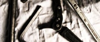
At this stage we will need the following tools and materials:
- hammer;
- thin punch or awl;
- 7mm wrench;
- slotted screwdriver;
- fine sandpaper;
- multimeter;
- medical syringe for 20 cc (optional);
- anti-rust liquid (WD-40 or equivalent);
- pencil and sheet of paper (to make a list of parts that will need to be replaced).
The procedure for disassembling and repairing the distributor is as follows:
Disconnect the device cover from the body. To do this, you need to bend the two metal latches by hand or using a screwdriver. We inspect the cover outside and inside. There should be no cracks or chips on it.
We pay special attention to the condition of the electrodes. If minor traces of burning are found, remove them with sandpaper.
If the contacts are severely burnt, or the cover has mechanical damage, we add it to the list of replacement parts.
We evaluate the condition of the runner. If it shows signs of wear, we add it to the list as well. Otherwise, clean the slider with sandpaper. Turn on the multimeter and switch it to ohmmeter mode (up to 20 kOhm). We measure the resistance value of the slider resistor. If it goes beyond 4–6 kOhm, we add the resistor to the list of future purchases.
Using a screwdriver, unscrew the two screws securing the slider. Let's take it off.
We inspect the weights of the centrifugal regulator mechanism. We check the condition of the springs by moving the weights in different directions. Under no circumstances should the springs be stretched or dangling. If they are hanging out, we make a corresponding entry in our list.
Using a hammer and a thin drift (you can use an awl), we knock out the pin that secures the shaft coupling. We remove the coupling.
We inspect the splines of the distributor shaft. If signs of wear or mechanical damage are detected, the shaft definitely needs to be replaced, so we “take a pencil” to that too. Using a 7 mm wrench, loosen the nut securing the condenser wire. Disconnect the wire. Unscrew the screw that secures the capacitor. Let's take it off.
We carry out diagnostics of the vacuum regulator UOZ. To do this, disconnect the second end of the hose that comes from the “vacuum manifold” from the carburetor fitting. We again put one of the ends of the hose on the fitting of the vacuum regulator reservoir. We place the other end on the tip of the syringe and, by pulling out its piston, we create a vacuum in the hose and reservoir. If you don’t have a syringe at hand, you can create a vacuum with your mouth, after first clearing the end of the hose of dirt. When creating a vacuum, the movable plate of the distributor must rotate. If this does not happen, most likely the membrane in the reservoir has failed. In this case, we add the tank to our list.
Remove the thrust lock washer from the axle. Disconnect the rod.
Unscrew the tank mounting screws (2 pcs.) with a flat screwdriver.
Disconnect the tank.
Unscrew the nuts (2 pcs.) securing the breaker contacts. To do this, we use a 7 mm wrench and a screwdriver, which we use to hold the screws on the back side. We dismantle the contacts. We inspect them and assess their condition. If they are badly burnt, we add the contacts to the list.
Using a slotted screwdriver, unscrew the screws that secure the plate. Let's take it off.
We remove the movable plate assembly with the bearing from the housing.
We check the bearing for play and jamming by shaking and turning the inner ring. If these defects are identified, we prepare it for replacement. We purchase parts according to our list. We assemble the distributor in the reverse order, replacing the failed elements with new ones. There is no need to install the cover and slider yet, since we will still have to set the gap between the contacts.
Replacing the wiring yourself
If there are numerous problems in the car's electrical system, you should think about completely replacing the wiring, rather than individual sections. When laying new wires, it is not recommended to combine low voltage wires with high voltage wires into one bundle. Reliable fastening to the housing will prevent pinching of wires and damage to the insulation. Appropriate plug blocks will ensure tight contact, which will eliminate the occurrence of breakdown and oxidation.
Numerous wires are hidden behind the instrument panel
Replacing the wiring can be done independently by a car enthusiast who has a superficial knowledge of electrics.
Reasons for replacement
The amount of work depends on the degree of significance of the reason:
- malfunctions of lighting devices;
- interruptions in the operation of electronics;
- significant oxidation of contacts;
- frequent lack of current in the wires;
- battery discharge;
- numerous damage to wire insulation;
- lots of twists.
To replace part of the electrical wiring in the cabin, you need to prepare:
- electrical components connection diagram;
- wires with different sections and colored insulation;
- electrical tape;
- connecting blocks;
- wire terminals;
- crimping pliers.
Replacement steps
Replacement of wiring should be carried out in accordance with safety rules and electrical diagram:
- Disconnect battery.
- Remove decorative plastic elements in the interior.
- Determine the location of the required wire bundle.
- Mark the wires to be replaced on the diagram.
- Disconnect the connectors and carefully, without pulling, remove the old wires.
- Lay new wires.
- Connect the pads.
- Make sure the wires are located according to the diagram.
- Install decorative elements.
- Connect the battery.
When owning a car with a long history, the wires should be replaced as a set.
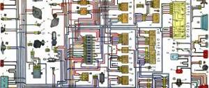
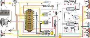
When replacing the wiring on the instrument panel, you should be guided by the connection diagram.
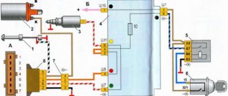
The search for faulty electrical appliances should begin with their connection diagram
Position numbers of electrical circuit elements on the diagram of control devices:
- Oil pressure warning light sensor.
- Coolant temperature gauge sensor.
- Level indicator and fuel reserve sensor.
- Fuel reserve warning lamp.
- Indicator lamp for parking brake and brake fluid level.
- Oil pressure warning lamp.
- Fuel level indicator.
- Instrument cluster.
- Coolant temperature gauge.
- Fuse box.
- Ignition switch.
- Generator.
- Accumulator battery.
- Parking brake warning light relay.
- Parking brake warning lamp switch.
- Brake fluid level sensor.
Contactless distributor
The device of the VAZ 2101 non-contact type breaker-distributor is similar to the contact type. The only difference is that the mechanical breaker is replaced by a Hall sensor. This decision was made by the designers due to the frequent failure of the contact mechanism and the need to constantly adjust the intercontact gap.
In a contactless ignition system, the Hall sensor acts as a breaker
Distributors with a Hall sensor are used in non-contact ignition systems. The design of the sensor consists of a permanent magnet and a round screen with cutouts mounted on the shaft of the chopper-distributor. As the shaft rotates, the screen cutouts alternately pass through the magnet groove, which causes changes in its field. The sensor itself does not generate an electrical pulse, but only counts the number of revolutions of the distributor shaft and transmits the received information to the switch, which converts each signal into a pulsating current.
Sound signal device for VAZ 2107
VAZ 2107 cars are equipped, depending on the year of manufacture, with two versions of the sound alarm. On models since 2000, a sound signal is installed on the VAZ 2107, consisting of two separate devices. One source produces low tones, and the second high. The devices are fixed directly to special brackets and are located on the left side of the radiator, under the grille.
Early models of VAZ 2107 cars are equipped with non-separable sound emission sources that produce only one tone. The product is also mounted on the front part near the radiator. The connection diagram of the element is simple, and in case of failure, eliminating the damage will not be difficult.
The sound signal device for 2 sources has the following form:
- Two wires are connected to the source of sound creation. One of the wires is red and the other is black. The red wire is the positive contact, which is constantly energized with 12V.
- The second wire is “minus” - it is de-energized and turns on only when the contacts are closed. As soon as the contacts are connected, current is supplied to the equipment, thereby generating sound vibrations.
The contacts are located on the steering wheel, and when you press the button, they close. Springs with a slip ring are used as contacts. The contact ring is located on the back of the steering wheel and provides high-quality contact when pressing the button. In addition to sources and a button, the design of the VAZ 2107 sound alarm also includes a relay and a fuse. The relay is designed to reduce the amount of current flowing to the device button.
Repair of contactless distributor
Diagnostics and repair of a non-contact type distributor are carried out by analogy with the instructions given above. The only exception is the process of checking and replacing the Hall sensor.
It is necessary to diagnose the sensor without removing the distributor from the engine. If you suspect that the Hall sensor is not working, check it and, if necessary, replace it in the following order:
- Disconnect the central armor wire from the corresponding electrode on the distributor cover.
- Insert a known-good spark plug into the wire cap and place it on the engine (body) of the car so that its skirt has reliable contact with ground.
- Have an assistant turn on the ignition and crank the starter for a few seconds. If the Hall sensor is working properly, a spark will appear at the spark plug electrodes. If there is no spark, continue diagnostics.
- Disconnect the sensor connector from the device body.
- Turn on the ignition and close terminals 2 and 3 in the connector. At the moment of short circuit, a spark should appear on the electrodes of the spark plug. If this does not happen, continue diagnostics.
- Switch the multimeter switch to voltage measurement mode in the range of up to 20 V. With the motor turned off, connect the device leads to pins 2 and 3 of the sensor.
- Turn on the ignition and take readings from the device. They should be in the range of 0.4–11 V. If there is no voltage, the sensor is clearly faulty and must be replaced.
- Carry out the work provided for in paragraphs. 1–8 instructions for dismantling the distributor, as well as pp. 1–14 instructions for disassembling the device.
- Using a flat-head screwdriver, unscrew the screws securing the Hall sensor.
- Remove the sensor from the housing.
- Replace the sensor and reassemble the device in the reverse order.
Replacement and repair of VAZ sound signal
The most common reason for the absence of a sound signal lies in the signals themselves. The reason is mechanical, moisture and oxidation lead to blocking of the sound membrane and, as a result, the absence of vibrations and sound effect. Sometimes you can restore functionality by spraying the signal with WD-40 or a similar composition.
Video:
On cars, where two signals are installed, as a rule, they are of different tones, low and high. If one signal fails, the second will not be able to fully provide the required power, and therefore requires replacement. As a rule, many signals are equipped with a tone adjustment screw, and if there are wheezing, grinding and other unwanted sound effects, you can use the adjustment to achieve a suitable sound. Also, with their help, you can move the “soured” membrane, thereby restoring the functionality of the signal.
Step-by-step instructions for replacing and repairing the sound signal of a VAZ 2106
- You can adjust the signal without dismantling it. This is done as follows:
- The sound elements are adjusted one by one. This turns off the power from the element that is not currently being regulated.
- The second GE is regulated in the same way, having first turned off the first one.+
- When replacing a faulty electrical element, the power wires are disconnected from it and the nut securing it to the bracket is unscrewed.
- The new sound signal is installed in the reverse order.
We diagnose the signal and its activation buttons
In order to find out whether your car uses a correctly working signal, you should disconnect its wires from the relay and connect them directly to the battery. If the sound does not appear in this case, the causes of the breakdown may be the following:
- contacts located directly in the device body are burnt or heavily soiled;
- The signal is not configured correctly, causing the dial tone to sound very low or not audible at all.
Troubleshooting is done by adjusting the signal (to do this you just need to turn a special screw installed in the back of the case) and cleaning the contacts.
Another reason why the signal may not work is a broken or worn button. To restore its normal functioning, you can either replace the entire part, or again put the contacts to which the wires are connected in perfect order.
As you can see, you don’t have to go to a car service center to diagnose and repair the sound signal. Almost any work can be easily done with your own hands without spending a lot of time on it. We only strongly recommend that you do not delay this, so as not to expose yourself to the risk of a traffic accident due to a non-functioning horn.
On the VAZ 2105 car, two types of sound signals can be installed - single and double. As a rule, the main repair work that needs to be carried out with the signal is its adjustment of the tone of the sound produced, or dismantling it in order to completely replace it with a new one in case of failure. Since they cannot be repaired, if they break, they are replaced. We carry out dismantling on a de-energized vehicle, disconnecting the minus terminal from the battery. To carry out repair work, prepare a standard set of tools, and then perform the following sequence of actions:
- Disconnect the power cables from the signal.
- Next, use a thirteen wrench to unscrew the nuts securing it to the bracket and remove it.
This completes the removal repair work. Replace it, and then perform the installation in the reverse order.
To adjust the sound tone, do the following:
- In the case of a double signal, we adjust each one separately; to do this, we disconnect the supply wire from the second one.
- Find the adjustment screw on the body, then ask an assistant to press the horn button, while you, in the meantime, turn the screw with a screwdriver to achieve optimal sound.
- If the bad sound cannot be eliminated, we replace it.
At this point, the repair work on replacing and adjusting sound signals on the VAZ 2105 has been completed.
Sources
- https://ladaautos.ru/vaz-2107/pochemu-ne-rabotaet-signal-na-vaz-2107-i-chto-delat.html
- https://remont-vaz2106.ru/vaz-2105-zamena-i-regulirovka-zvukovogo-signala
The horn button does not work, what should I do?
If, when diagnosing the electrical circuit breaker, the fuse and the circuit breaker relay, no faults are identified, then you need to check the signal activation button on the steering wheel. Since the steering wheel itself is constantly rotating, and the need to sound a signal can arise at any time, there is a moving contact between the steering wheel and the steering column. Using this contact, you can close the circuit even when turning the steering wheel. In addition, the button itself has two more contacts that allow the driver to give a signal with both the left and right hand. Any of these contacts (most often movable) can fail. In this case, you need to clean it and make sure the button is working. This is done as follows.+
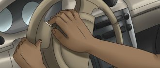
- We install the car wheels straight. The steering wheel should also not deviate to the side.
- Use a screwdriver to pry off the Lada emblem from the steering wheel button.
- Using a 24mm socket, unscrew the steering wheel nut located under the emblem.
- Holding and slightly rocking the steering wheel with both hands, remove it from the shaft. In this case, if the steering wheel is not removed, you can hit the shaft through the spacer.
- Using a Phillips screwdriver, unscrew the four bolts on the back of the steering wheel and remove the horn button
- Remove the button from the steering wheel and disconnect the wire from the contact on the steering wheel. Use a needle file or sandpaper to clean the moving contact located near the shaft on the steering column. Slightly bend the contact upward (towards the steering wheel)
- On the previously removed signal button, clean both contacts.
- We remove and clean the wires and contacts removed from the button
- After cleaning the contacts, we assemble the button. At the same time, we make sure that all contacts are in contact with each other.
To prevent the signal from triggering spontaneously, we check whether the springs of the signal button have weakened. If necessary, stretch the springs or replace them with new ones.
We install the steering wheel on the shaft in the position it was before disassembly.
Sound signal circuit and its repair
SOUND SIGNAL DEVICE
The sound signal on the VAZ 2107 comes in the following versions:
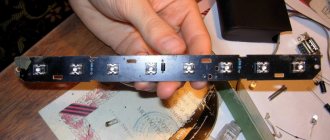
- Two separate signals: type S-304 (low tone) and S-305 (high tone). Mounting - on the bracket, to the left of the radiator.
- The only non-separable signal of type 20.3721-01, one tone, with a built-in relay. Mounting is on a bracket outside the radiator, immediately behind the decorative grille.
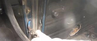
The operation diagram of the sound signal is as follows: two wires are connected to the sound signal itself. The red wire is “plus”. This part of the circuit is constantly energized. The gray-black wire is “ground, minus”; in the normal state it is de-energized, and current begins to flow through it when shorted. The photo clearly shows the color of the wires and two separate signals with brackets.
The “negative” part of the chain is long. When you press the central steering wheel button, the spring contacts close. They are located in the switch housing under the steering wheel.
The slip ring is attached to the back of the steering wheel. Its task is to ensure good contact through friction and provide a signal whenever the steering wheel is turned. Therefore, the ring must be lubricated with conductive graphite lubricant to avoid wear.
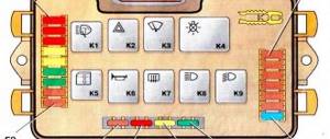
Then, the current is transmitted through the wire as part of the engine compartment harness to the switch and relay mounting block. The location of the horn relay (switch) is third on the right (if you are sitting behind the wheel).
Horn relay functions:
- The length of wires and current losses in them are reduced.
- With the help of a relay, a button with a small current can control a circuit with a large load.
Sometimes the circuit does not provide a relay; instead, a jumper that is connected “directly” works. In the case of a single signal 20.3721-01, this is justified, since it has a built-in relay. If there are two “snails”, it is advisable to install a relay to improve operation.
After the relay, the current passes through fuse F7. The new mounting blocks have a 20 A flag-type fuse, yellow. Older units have 16 A fuses. Their lifespan is often insufficient, since this fuse also serves in the cooling fan circuit.
Further, after leaving the mounting block as part of the wiring harness of the engine compartment, the “negative” wire goes directly to the sound signal.
Possible malfunctions: signs and causes
In order to understand the reasons why the horn does not work, you need to understand:
The circuit consists of the following components:
- sound devices;
- mounting block;
- jumpers for contacts installed in place of the relay;
- signal switch.
The sound signal is activated by a button located in the center of the steering wheel.
There is a contact ring on the steering wheel, and a spring-loaded contact in the area of the steering column switches. Modern ones are equipped with an adjusting screw for adjusting the volume and a built-in relay (in the mounting block, the relay outputs for the sound signal are short-circuited with a jumper).
Signs of malfunction:
- no sound when pressing a button;
- The sound does not turn off or turns on randomly;
- hoarse, quiet or intermittent sound.
The audio system carries low voltage current, so the quality of the connections is important.
If there is a large amount of oxides and rust on the contacts, then the passage of current becomes difficult. Klaxons require a powerful current of at least 4-5 A.
It is necessary to carefully monitor the cleanliness of connections and terminals, otherwise repairs will be needed constantly. Since the car body acts as a minus, and oxidation settles on the plus, special attention should be paid to stripping the terminals on the positive red wire.
The negative branch of the chain is the longest, so it is most likely to have a break. To determine the cause of the malfunction, you need to connect the gray-black wire coming from the signaling device to the body, and the positive wire directly to the battery. Then . If the sound appears, it means there is a break in the minus value. If there is no sound and the positive terminals are cleaned, then the device has failed.
If the sound signal on a VAZ 2107 does not work, the following malfunctions are possible:
- fuse is blown;
- contacts and terminals have oxidized;
- the relay has failed;
- the connections on the jumper, if present, have oxidized;
- the paddle on the steering column relay broke;
- development of a slip ring.
After diagnostics, the faults found should be eliminated (video author - Alex Life).
Distributor malfunctions, their symptoms and causes
Taking into account the fact that the designs of contact and non-contact type distributors are almost the same, their malfunctions are also identical. The most common breakdowns of the breaker-distributor include:
- failure of the cover contacts;
- burning or wear of the runner;
- changing the distance between the breaker contacts (only for contact distributors);
- failure of the Hall sensor (only for contactless devices);
- capacitor failure;
- Damage or wear of the movable plate bearing.
Let's look at the malfunctions in more detail in the context of their symptoms and causes.
Failure of cover contacts
Considering that the cover contacts are made of relatively soft materials, wear is inevitable. In addition, they often burn out, because a current of several tens of thousands of volts passes through them.
The more wear on the contacts, the greater the likelihood of them burning.
Signs of wear or burning of the cover contacts are:
- “triple” of the power plant;
- complicated engine starting;
- reduction in power characteristics;
- unstable idle.
Burnt or worn contact of the slider
The situation is similar with the slider. And although its dispensing contact is made of metal, it too wears out over time. Wear leads to an increase in the gap between the contacts of the slider and the cover, which, in turn, provokes the formation of an electric spark. As a result, we observe the same symptoms of engine malfunction.
The runner is also subject to wear and tear over time.
Changing the gap between contacts
The intercontact gap in the VAZ 2101 distributor breaker should be 0.35–0.45 mm. If it goes out of this range, malfunctions occur in the ignition system, which affects the operation of the power unit: the engine does not develop the required power, the car jerks, and fuel consumption increases. Problems with gap in the breaker occur quite often. Owners of cars with a contact ignition system have to adjust the contacts at least once a month. The main reason for such problems is the constant mechanical stress to which the breaker is exposed.
When changing the set gap, the sparking process is disrupted
Hall sensor failure
If problems arise with the electromagnetic sensor, the engine also begins to experience interruptions: it starts with difficulty, periodically stalls, the car jerks during acceleration, and the speed fluctuates. If the sensor breaks down altogether, you are unlikely to be able to start the engine. It rarely fails. The main sign of its “death” is the lack of voltage on the central high voltage wire coming out of the ignition coil.
If the sensor fails, the engine will not start
Capacitor failure
As for the capacitor, it also rarely fails. But when this happens, the breaker contacts begin to burn. You already know how it ends.
If the capacitor is broken, the breaker contacts burn out
Bearing failure
The bearing serves to ensure uniform rotation of the movable plate around the shaft. If it malfunctions (biting, jamming, backlash), the ignition timing regulators will not work. This can cause detonation, increased fuel consumption, and overheating of the power plant. It is possible to determine whether the moving plate bearing is working properly only after disassembling the distributor.
If a bearing malfunctions, interruptions in regulation of the SOP occur
Checking the functionality of the relay and fuse
What to do if the signal on a VAZ-2107 car does not work, and for what reasons can it fail? The most common one is a blown fuse. Under increased load, it fails and interrupts the electrical circuit, thereby eliminating more serious emergency situations.
If you are faced with the problem of a blown fuse, you must replace it immediately. In addition, you will need to carefully inspect the contacts of this part, carefully clean them of carbon deposits and dirt, or perform repairs.
The next stage of diagnostics is to check the functionality of the sound signal relay. If it clicks when you press the button, then the cause of the breakdown needs to be looked for elsewhere. Otherwise, the relay will need to be replaced, which can be done within a few minutes even without the relevant experience.
The main reasons why the VAZ sound signal does not work
The main reasons for the non-working sound signal of a VAZ 2106 - 2114 car include:
- Fuse faulty . The very first and easiest check that can be performed when the sound signal is not working is the integrity of the fuse. If it turns out to be burnt out, then there may be a short circuit in the car. Try inserting a whole fuse that matches the rating (How to choose a fuse. Colors and ratings). If it burns out in the same way, it means there is actually a short circuit. If not, then perhaps the fuse has simply exhausted its resource and you should pay attention to other reasons.
- The horn button does not work . The signal in most cars is turned on by a button in the center of the steering wheel. There are variations with a button in the steering column switch or a certain position of this switch itself, but this is rare. There are actually a whole bunch of places inside the steering wheel where contact can be lost, leading to the failure of the horn. To understand exactly where they can be located, you need to understand how the sound signal in the car turns on. Let's look at the diagram.
- Worn contacts . The pressure contacts on the steering column rub against the slip ring whenever you move the steering wheel and wear out over time. Sooner or later, a moment may come when they can no longer reach the contact ring on the steering wheel and then pressing the horn button will lead to nothing. To avoid this, when removing the steering wheel for any repairs, it is necessary to lubricate the contacts and the ring on the steering wheel with a conductive lubricant, for example, graphite. Such treatment will reduce the friction of the contacts on the ring and extend their service life.
- Worn slip ring . Exactly the same malfunction can befall the conductive ring in the steering wheel. It can also wear out and lead to signal failure. The method of struggle is the same - lubricant. The wear of the clamping contacts or slip ring has an insidious property: due to uneven wear, the contact may disappear only at certain steering wheel positions. For example, when driving straight, the signal works, but when turning, it does not. Such symptoms almost always clearly indicate problems in the contact pair “steering column - steering wheel”.
- Oxidized contacts inside the steering wheel . Another “steering” problem is the oxidation of internal contacts. Due to the large amount of oxides, a sufficient amount of current cannot pass through the contacts inside the steering wheel and the sound signal is silent. You need to disassemble the steering wheel and clean the contacts.
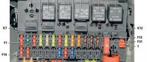
What is a fuse box for in a car circuit?
Using the VAZ 2101 fuse box, it is possible to achieve the maximum degree of protection against short circuits. The block includes several fusible elements, which, in the event of a short circuit, open one or another circuit. All electrical wiring of the VAZ 2101 is divided into component parts. Therefore, if there is a short circuit, for example, in the cigarette lighter power circuit, the engine will still start and you will be able to get anywhere. All fuses are located in one place - this allows you to inspect the electrical wiring and diagnose it as quickly as possible.
It is also worth paying attention to one feature of the car diagram - all lighting is divided into two halves (left and right). There is a 50/50 chance that both fuses will blow at once, so in most cases your car will have lighting on at least one side
To make repairs, just open the unit cover and, using the table above, find the required element and replace it with a similar one. Please note that you cannot install fuses of a higher or lower rating, since in the first case the electrical wiring of the VAZ 2101 will suffer (the insulation is designed for lower currents), and in the second the fuse element will burn out at the slightest load.