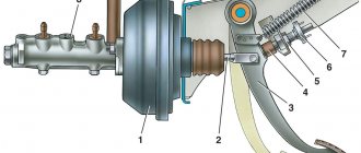
The design of the ignition switch consists of the main elements:
- device body;
- turnkey larva;
- locking mechanism;
- ignition switch contact group.
During prolonged use of the vehicle, malfunctions in the operation of the ignition switch are possible - as a result of oxidation of the contacts or mechanical damage to the wiring. It is necessary to periodically replace the contact group of the ignition switch and repair the locking mechanism.
Read in more detail about how to repair the ignition switch yourself in the material from our specialist.
Design and functions of the ignition switch contact group
Functional elements of the lock: rotary control element and contact group. The main function of the ignition switch contact group is to close the contact terminals and connect elements in the electrical circuit. Changing the position of the key allows you to perform the following steps sequentially:
- close the power circuits of electrical appliances and lighting systems;
- supply current to the spark plugs and starter;
- start the car engine.
To avoid involuntary short circuits between the elements, the wiring is made through a block on the end wall, and the contact planes are hidden in a polymer shell.
Principle of operation
Turning the key closes the circuit and allows power to be supplied from the battery to the coil. Voltage is transmitted to the spark plugs through wires. The starter begins to spin the engine - the fuel mixture ignites in the combustion chamber, the engine starts and starts working.
The first key switching mode allows you to unlock the steering wheel. The steering mechanism locking system is designed for safety - with an anti-theft purpose. The following key position in the ignition switch allows:
- turn on the instrument panel lighting;
- parking lights;
- use brake lights and hazard lights.
It is possible to gain access to the ignition switch contact group by removing the plastic panel with the locking mechanism.
How does the ignition switch work?
Of course, you begin to blame any additional components installed on the car. In addition, after a certain number of attempts the car still starts. Car diagnostics do not bring any results. The diagnostician does not detect errors even when the device is connected, and the machine works properly. And no matter what complaints the client has about fate, that the car doesn’t work in the morning, the diagnostician will only have to spread his arms to the sides, because everything works. And it’s not uncommon for a diagnostician to fault the Bastion ignition switch, believing that all the “glitches” are caused by it. In this case, you just need to understand how the Garant-Bastion castle works.
Castle "Bastion".
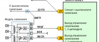
Structurally, the Bastion lock is an analogue of a conventional ignition switch. Its main function, in addition to the steering lock function, is to turn on the ignition and starter. There are only 3 wires in the key block. Brown or pink supplies power to the lock, coming directly from the generator and battery. Blue-black turns on the ignition. Red is used to turn on the starter. That's all! Therefore, if the instruments turned on, the warning lights flashed, then the ignition also turned on. If, when the starter button is pressed (if we talk about the Single lock), the starter rotates, then this locking chain also works. If the car does not start, then it is definitely not the ignition switch. The only thing you should pay attention to is reading the key code. If it is impossible to identify the key, and a possible reason for this may be a malfunction of the remote control itself, which controls the standard anti-theft alarm, then 5-6 seconds from the moment the ignition is turned on, a flashing lamp will light up on the instruments (yellow frame of the car and the key in its background). If the lamp does not light up and the system recognizes the key, then all the work of the ignition switch is completed. If the engine still does not start, then the problem must be looked for everywhere except the Bastion ignition switch. Below we provide information about the standard ignition switch.
Lada Priora cars are equipped with an ignition switch 11180-3704010, which has a theft locking device, blocking of repeated activation of the starter without preventive switching off the ignition, as well as a coil for connecting the ignition key transponder with the car's anti-theft system.
The correct closure of the contacts at the ignition switch is checked at different key positions, the operation of the anti-theft mechanism and the presence of communication with the car's anti-theft system. Voltage is supplied to the contact from the battery and generator. To relieve the load on the ignition switch contacts, a special relay K4 is installed inside the mounting block. The anti-theft device extends the locking rod when the key is placed in the “0” (off) position and removed from the ignition switch. The locking rod is retracted when the key is turned from position “0” (off) to position “I” (ignition). The key can only be removed from the ignition switch in the “0” position.
The starter restart interlock device is not required to allow the next turn of the key from position “I” (ignition) to position “II” (starter). Turning the ignition key to this position should only become possible when the key is returned to the “0” (off) position.
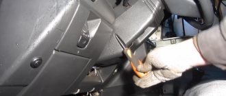
Well, now it's time to remove the ignition switch. The ignition switch is designed in such a way that to remove and disassemble it we will need: a chisel, a hammer, a screwdriver with a flat blade.
Next, disconnect the wire from the negative terminal of the battery. Remove the steering column cover. Next, we press the latch. And disconnect the block with all the ignition switch wires from the dashboard wiring harness. Next, we disconnect and also disconnect the block with the wires of the ignition switch from the harness with the wires of the system that controls the immobilizer.
Next, use a hammer and chisel to unscrew or drill out four bolts with break-away heads and remove the ignition switch from the steering column.
Then we bend the clamp of the ignition switch wiring harness block and remove the terminal with wires from the block. Then you need to squeeze the latches and remove the plastic cover from the ignition switch housing. After completing the procedures, you need to bend the two plastic latches. Then you need to remove the contact group from the lock cover. Next, we inspect the contacts. Burnt or oxidized contacts must be cleaned using fine-grained sandpaper. In case of serious damage to the contacts, it is necessary to replace the contact group or the entire ignition switch assembly.
After damage is detected, or, conversely, not detected, it is necessary to reassemble the ignition switch in the opposite order of removal. In this case, you need to pay attention to the position of the terminals with wires in the block containing the wiring harness.
Next, install the ignition switch in the reverse order of removal, initially recessing the locking rod of the anti-theft device. To do this, insert the key into the lock and turn it from position “0” to another position.
When changing the lock, you need to change the electronic code components (transponders) in the ignition key heads of the updated lock using the corresponding code elements of the keys from the ignition switch that was removed from the car. There is no need to carry out a training procedure after this replacement.
Reasons for failure
Malfunctions of the lock elements are reflected during vehicle operation. Problems arise when starting the engine and manifest themselves as:
- intermittent starter operation;
- unusual extraneous relay clicks;
- slow response when changing key positions or complete lack of response.
Sometimes there are situations when the car cannot be turned off. Failure can be diagnosed by examining the elements of the contact group for oxidation.
Mechanical
If the key jams in the lock cylinder, the fault is looked for in the structural elements of the device. The entry of dust particles into the keyhole is accompanied by clogging and premature mechanical wear. In this case, the entire lock will need to be replaced.
Often the problem is the wear of the wire sheath - this happens due to mechanical rubbing against each other.
You should check the tightness of the terminal contacts, and check the cracked insulation for integrity. Replace damaged sections of wiring and tighten the terminals for tight contact.
The internal parts of the keyway also wear out. To increase service life, lubricant is regularly added inside the larvae. A mechanical break in the geometry and wear of the key cannot be ruled out - you will need a spare copy or a duplicate made in advance.
Electrical
The need for premature replacement of the contact group arises when the device is overloaded. Over time, the contact winding elements burn out due to overheating. The resulting internal carbon leads to a violation of the density of the contact spots and the throughput function of the circuit load.
When installing additional sound and light elements, check the devices for matching current strength. Additional devices are connected to the electrical circuit using special relays or fuses.
Operating principle of the ignition switch
The lock's operating system is quite simple, so now let's look at the main tasks it can handle:
- The ability to connect and disconnect the vehicle’s electrical power system to the battery, in turn, after starting the engine, connect to the generator.
- Ability to connect and disconnect the engine ignition system to the power source.
- When the engine is started, the ignition switch may turn on the starter for a short period of time.
- Ensures the operation of such devices when the engine is off , such as: radio and alarm.
- Some ignition switch features can be used as an anti-theft feature , such as the ability to lock the steering wheel when the engine is at rest.
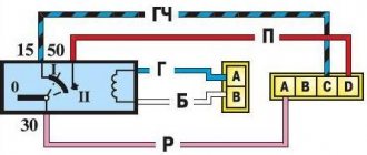
Ignition switches can have from two to four switch positions. Depending on the position of the ignition key in the car, you can determine which power systems are working at one time or another. The key in the car can only be pulled out in one position, when all power consumers are turned off. To have a more detailed understanding of the operation of the ignition switch, you need to familiarize yourself with its diagram:
Ignition switch operation diagram
In what positions can the ignition switch operate?
- "Turned off" . In cars of domestic manufacturers, this position is displayed as “0”, but on some older models the position had the value “I”. Today, in improved cars, this mark is not displayed on the lock at all.
- “On” or “Ignition” - on domestic cars the following designations are found: “I” and “II”, in newer versions it is “ON” or “3”.
- “Starter” - domestic cars “II” or “III”, in new cars – “START” or “4”.
- “Lock” or “Parking” - old cars are designated “III” or “IV”, foreign cars are marked “LOCK” or “0”.
- “Additional equipment” - domestic locks do not have this provision, foreign versions of the car are designated: “Ac” or “2”.
Ignition switch position diagram
When the key is inserted into the lock and turned clockwise, that is, it moves from the “Lock” to the “ON” position, then all the main electrical circuits of the car are turned on, such as: lighting, windshield wiper, heater and others. Foreign cars are designed a little differently; they have “Ass” immediately before the “ON” position, thus additionally starting the radio, cigarette lighter and interior lights. If you turn the key further clockwise, the lock will move to the “Starter” position, at this moment the relay should connect and the engine will start. This position cannot be locked because the key itself is held by the driver. After successfully starting the engine, the key returns to the initial position “Ignition” - “ON” and already in this state the key is fixed in one position until the engine stops completely. If it is necessary to turn off the engine, then in this case the key is simply turned to the “Off” position, then all power circuits are turned off and the engine stops.
Diagram of the key operation in the ignition switch
In cars with diesel engines, a valve is turned on to shut off the fuel supply and a flap that closes the air supply; as a result of all these actions, the electronic unit that controls the engine stops its operation. When the engine is completely stopped, the key can be switched to the “LOCK” position, after which the steering wheel becomes motionless. In foreign cars, in the “LOCK” position, all electrical circuits are turned off and the steering wheel is locked; cars with an automatic transmission additionally block the selector, which is in the “P” position.
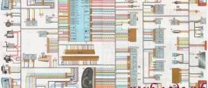
VAZ 2101 ignition switch wiring diagram
Checking the functionality of the ignition switch contact group
Diagnosis of the suitability of the ignition switch contact group is carried out with a device - a multimeter. The contacts are checked for changes in resistance.
Sequence of work
The performance of the part is checked in the following sequence.
- Disconnect the battery (you can only remove the “-” terminal).
- Disconnect the contacts of the wire block.
- The lock connectors are checked in different positions (pairs of contacts of the lower and upper rows).
Multimeter readings
When checking with a multimeter, we look for the following signs and readings of the device:
- Impossibility of measurement (infinity sign) - replacement of the contact group without the possibility of manipulation and repair.
- Fluctuations in the sensor needle (numbers on the screen) indicate intermittent contact. It will be necessary to check the terminals for tight connections and clean them from oxidation.
- Signs of a malfunction of the ignition switch contact group are zero readings on the multimeter.
- The next stage of troubleshooting is checking the electrical wiring for integrity.
You can check the functionality of wiring without a contact group by directly connecting pairs of corresponding wires. If the starter cranks and the engine starts, the circuit line from the battery to the spark plugs is fully functional, and the problem lies in the ignition switch system.
Types of ignition switches
All ignition switches are divided into several categories according to type, purpose and functionality.
There are two main types of ignition switches:
- With key;
- Keyless (ignition switches).
Key locks are the most common today and are installed on most cars and other vehicles. Keyless ignition switches were especially common in the early days of the automobile industry, and were installed on cars (especially trucks) into the 1940s and 1950s. Switches were then replaced by key locks, but today ignition switches are making a comeback. Modern keyless switches are more technologically advanced than the regular buttons found on older cars, but their functions remain roughly the same.
All existing ignition locks can be divided into two large groups according to the number of key positions:
- Locks with three key positions;
- Locks with four key positions.
Locks with three key positions are out of use today; they can only be found on older models of cars and trucks, especially domestically produced ones. Since the 1960s and 1970s, new four-position locks have been installed on cars, which have expanded functionality. The functionality of ignition switches will be discussed in more detail below.
Also, ignition locks can be divided into two groups according to the presence of an anti-theft system:
- Conventional locks without steering wheel lock;
- Locks with mechanical steering wheel lock.
The steering wheel is locked by almost all ignition locks with four key positions; old three-position locks do not have this function.
Finally, ignition locks can have various additional functionality, including protection against turning on the starter while the engine is running, a warning system for a key left in the lock, and others.
Regardless of the type and purpose, all ignition switches have fundamentally the same design and operating principle.
- Battery
- Starter
- Generator
- Relay in mounting block
- Egnition lock
- Start relay
How to replace a contact group?
The procedure for replacing a contact group is quite simple, provided you have the necessary tools and skills in working with electrical equipment. The main technical points are the marking of wires in relation to the sockets and the sequential implementation of work stages.
You can manually draw up a sketch of a circuit diagram of a working system, and use it to connect a new group in the correct order.
Step-by-step instruction
The procedure for replacing the ignition switch contact group is as follows:
- Unscrew the screws securing the steering shaft housing.
- Press the clips and remove the plastic panel to remove the ignition switch.
- The anti-theft mechanism is clamped with a screwdriver through the hole in the bracket and the lock core is pulled out.
- Carry out an inspection for mechanical wear of the elements, and also check the terminals for carbon deposits and oxidation.
- Check the steering wheel locking device with the rod extended and recessed.
- Check the resistance in the circuit (with a multimeter).
The functionality of the contact group is checked in all modes of the switching mechanism (ignition key position).
Having discovered a problem in the operation of the contact group or the ignition switch, replace it with new elements. Assembly is performed in the following sequence:
- alternately connect the wires to the connectors of the contact group and connect the clamps;
- first check the functionality of the system with a new contact group (in different positions of the ignition key);
- the wiring is tightened with polymer clamps;
- install the lock on new bolts (with caps that break off) in the steering column.
The special bolts are tightened until the heads break off. At the final stage, the casing and plastic panels are installed, and the assembly of the structure is checked for play.
Location
For most domestic and foreign cars, the ignition switch is structurally located in the steering column housing or under the panel of technical sensors. The contact group is located behind the plane of the ignition key cylinder.
It is typical for many vehicles to install the ignition switch on the right or left side of the steering column. Sometimes there are foreign car models where the lock and key are located on the car's dashboard or navigation panel.
This is interesting: Ford Focus 3 fuel filter
Replacing the ignition switch
We dismantle and change the lock according to a similar principle. Having disconnected the battery terminals, set the key in the ignition switch to the zero position “0”. After disabling the safety mechanism lock, remove the plastic panels of the steering column. We mark the connection wires. Dismantling the old unit:
- unscrew the screws and remove the protection;
- Use a chisel to knock down the clamps fastening to the column;
- disconnect the marked wires.
After diagnosis, minor damage to the old lock can be repaired in a workshop. Be sure to change the lubricant for the rubbing elements. If the old lock is completely unsuitable for use, you will need to select a model and purchase a new element. Installation of the device is carried out in the reverse step-by-step order.
Ignition switch repair
Larva
To replace faulty parts of the ignition switch, it must be disconnected and removed. To do this, be sure to follow the rules of caution and also have a screwdriver and an awl on hand. We will look at dismantling the lock using the example of “classic” VAZ car models (2101-2107). On these cars, the ignition switch is located on the lower left side of the steering column. In later models, the ignition key is moved to the right side of the steering column, which is generally convenient for right-handed drivers.
Removing the lock
Dismantling
- First of all, don’t forget to disconnect the battery; to do this, remove the negative terminal from it.
- We turn the key in the lock to the “zero” position, at which the key head is parallel to the floor.
- Using a screwdriver, unscrew the fastening screws of the decorative casing of the steering column column.
- Find and unscrew the two screws securing the ignition switch to the column. After this, the key does not fall into your hands, but remains in a fixed state. In later models, the lock can be secured with four break-away screws, which require a chisel and pliers to loosen.
- We tighten the lock latch by inserting an awl into the round hole on the left side of the bracket. While holding it, pull the key towards you.
- Disconnect the wires or the solid chip with wires. Now the castle is in your hands.
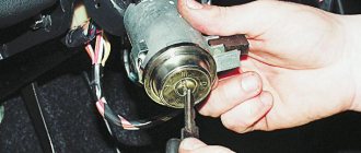
Replacing a faulty part
To replace one of the parts of the ignition switch, you need to disconnect it by prying off the retaining ring, and then install a new one in the same place.
Disassembling the ignition switch
Connecting contacts to the ignition switch
If the lock repair is completed, or a new lock is purchased, it must be connected and installed in its original location. This is very easy to do, especially if, when disconnecting the wires from the lock terminals, you marked them, or, even better, if the coil of wires ends with a solid chip. If not, then it doesn’t matter either.
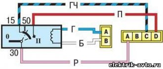
Typically, the lock's terminal block will have markings on it to help you connect the wires to the terminals correctly. Automotive instructions must specify what color wire should be connected to a terminal with a certain designation. We will look at the connection using the terminal block of VAZ cars (2101-2107) as an example.
Colored wiring
Your wire bundle should consist of a double black wire, a single pink wire, a double blue wire, a single brown wire, and a single red wire. We take the wires and sequentially, starting with black, connect them to the terminals with the designations: 1NT, 30, 15, 30/1, 50. After connection, the lower part of the only double terminal remains without a wire. Now the contacts are connected, and we can return the lock to its place.
Connectors
When installing the lock, we perform the above steps in reverse order: push the lock into the seat until the latch clicks, tighten the fastening screws, and return the upper and lower parts of the casing to their place. The repair is complete, now we need to make sure it is successful.