General diagram of electrical equipment of VAZ 1118
1 — block headlight; 2 — windshield wiper gear motor; 3 - generator; 4 - battery; 5 - starter; 6 — sound signal; 7 — hood open sensor; 8 — power window switch for the right front door; 9 — motor-reducer for window lifter of the right front door; 10 — electric pump for windshield washer; 11 — connecting blocks of wires for connecting the right (front) speaker of the audio system; 12 — electric drive for locking the lock of the right front door with an open door sensor; 13 — ambient air temperature sensor; 14 — connecting block of the wiring harness for connection to the engine control system harness; 15 — electric drive for locking the left front door lock (with an open door sensor and a central locking switch); 16 — sensor of insufficient brake fluid level; 17 — connecting blocks of wires for connecting the left (front) speaker of the audio system; 18 — right front door power window switch (installed on the driver’s door); 19 — left front door power window switch; 20 — central locking switch; 21 — motor-reducer for window lifter of the right front door; 22 — remote control unit; 23 — immobilizer control unit (APS-6); 24 — mounting block; 25 — instrument panel; 26 — right side turn signal; 27 — glove box lighting lamp; 28 — switch for the glove compartment lighting lamp; 29 — brake signal switch; 30 — ignition switch (lock); 31 — lighting control unit; 32 — steering column switches; 33 — left side direction indicator; 34 — connecting blocks of wires for connecting the left (rear) speaker of the audio system; 35 — electric drive for locking the left (rear) door with an open door sensor; 36 — electric heater fan; 37 — additional heater resistor; 38 — heater switch; 39 — alarm switch; 40 — reverse lock solenoid switch; 41 — rear window heating switch; 42 — connecting blocks of wires for connecting the right (rear) speaker of the audio system; 43 — electric drive for locking the right rear door lock (with a door open sensor); 44 — fuel module of the engine control system; 45 — reverse light switch; 46 — parking brake warning lamp switch; 47 — cigarette lighter; 48 — reverse lock solenoid; 49 — connecting blocks of wires for connecting the head unit of the audio system; 50 — backlight lamps on the trim of the center console of the instrument panel; 51 — electric power steering control unit; 52 — interior lamp; 53 — rear light; 54 — block for connecting the electric drive for locking the trunk lid lock*; 55 — luggage compartment lid open sensor; 56 — license plate lights; 57 — additional brake light; 58 — rear window heating element; 59 — luggage compartment lighting lamp.
Replacing the ignition switch yourself
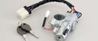
Unfortunately, the Lada Kalina cannot please you with its reliability and durability; many systems, including the ignition switch, fail within a couple of years, so in order to save on repairs at expensive car repair shops, it is better to find out how to do it yourself. So, having come to the conclusion that the lock needs to be changed, we buy a new lock, which costs around a thousand rubles. In the kit we will receive three cylinders (on the doors and trunk) and 2 keys. You also need to purchase four shear bolts , since the old ones will no longer be suitable after dismantling.
In addition to the product itself, we will need the following tools:
- chisel;
- two screwdrivers, a flat one for removing the clamps and a cross for the bolts;
- 10mm wrench or 10mm ratchet;
- key to 8.
Let's get started
1. First you will need to disconnect the battery cable from the negative.
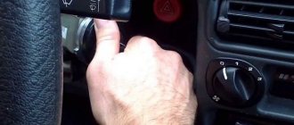
2. Armed with a cross-head screwdriver, unscrew the fasteners on the steering column. To make it more convenient for you, we immediately warn you: there are two bolts on the right and left sides (3), two at the bottom in the middle (2), and two at the very bottom (1). There is also a self-tapping screw located directly under the steering wheel (4).
3. We take out the clamps holding the steering column switches. We dismantle the switches.
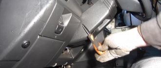
4. Now we need the help of a chisel. It is necessary to apply blows of medium power and unscrew the bolts. Bolts, as a rule, become very sticky after several years of use, so you will have to work hard. As soon as you notice that the bolts begin to move out of place, you can pick up pliers and continue to work only with their help.
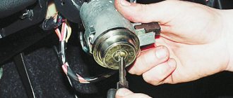
5. We need to get to the lock connectors, of which there are only two (main power and immobilizer antenna). The connectors are hidden under the console casing. To gain access to the connectors, you need to slightly pull the wiring harness away from the lock and pull them out.
6. Unplug the connectors, and then remove the ignition system switch.
Now we replace the old lock with a new one and reassemble it in the reverse order. But don’t forget that you need to do a little more magic on the doors and trunk, changing the lock cylinders.
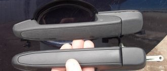
Replacing door cylinders
To remove the old cylinders on the doors and trunk, you need to carry out a simple job consisting of several stages.
1. Take a 8mm wrench (or a 8mm socket with a ratchet) and a Phillips screwdriver. 2. Unscrew the screws from the door trim and remove it.
3. After removing the casing, you need to use a 8mm head to unscrew the iron figured holder (3 bolts).
Lada Kalina dashboard diagram
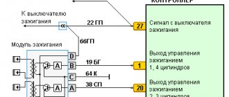
1,2,3,4 – blocks of the instrument panel wiring harness to the blocks of the rear wiring harness; 5,6 – blocks of the instrument panel wiring harness to the blocks of the front wiring harness; 7 – block of the instrument panel wiring harness to the block of the wiring harness 8 – block of the instrument panel wiring harness to the block of the front wiring harness; 9 – lighting control module; 10 – ignition switch; 11 – on-board computer mode switch; 12 – windshield wiper switch; 13 – sound signal switch; 14 – light signaling switch; 15 – instrument cluster; 16 – evaporator temperature sensor; 17 – interior air temperature sensor; 18 – air conditioner switch; 19 – controller of the automatic climate control system; 20 – heater damper gearmotor; 21 – rear window heating switch; 22 – alarm switch; 23 – brake signal switch; 24 – cigarette lighter; 25 – electric amplifier control unit; 26,27 – blocks of the instrument panel wiring harness to the radio; 28 – backlight lamp for the heater control panel; 29 – illuminator; 30 – mounting block: 31 – heater electric motor switch; 32 – heater electric motor; 33 – additional resistance of the heater electric motor; 34 – glove box lighting; 35 – glove box lighting switch; 36 – control unit of the APS-6 automobile anti-theft system; 37 – driver airbag module; 38 – passenger airbag module; 39,40 – blocks of the instrument panel wiring harness to the blocks of the ignition system wiring harness.
KZ – additional starter relay; K4 – additional relay; K5 – relay-interrupter for direction indicators and hazard warning lights; K6 – windshield wiper relay; K7 – headlight high beam relay; K8 – sound signal relay; K9 – relay for turning on fog lights; K10 – relay for turning on the heated rear window; K11 – electric seat heating relay; K12 – air conditioner compressor clutch activation relay;
Instrument panel wiring harness – 11186-3724030-20.
Ignition system diagram Lada Kalina Lux
1 – oil pressure warning lamp sensor; 2 – coolant temperature indicator sensor; 3 – additional fuse block; 4 – fuses for the electric fan of the engine cooling system; 5 – electric fuel pump relay; 6 – relay for the electric fan of the engine cooling system; 7 – ignition relay; 8 – relay 2 of the electric fan of the engine cooling system; 9 – relay 3 of the electric fan of the engine cooling system; 10 – electric fan of the engine cooling system; 11 – throttle position sensor; 12 – idle speed regulator; 13 – coolant temperature sensor; 14 – diagnostic block; 15 – ignition system harness block to the instrument panel harness block; 16 – solenoid valve for purge of the adsorber; 17 – speed sensor; 18 – ignition system harness block to instrument panel harness block 2; 19 – mass air flow sensor; 20 – crankshaft position sensor; 21 – oxygen sensor; 22 – controller; 23 – rough road sensor; 24 – diagnostic oxygen sensor; 25 – ignition coil harness block to the ignition system harness block; 26 – ignition coils: 27 – ignition system harness block to the ignition coil harness block; 28 – spark plugs; 29 – nozzles; 30 – resistor; 31 – air conditioning system pressure sensor; 32 – blocks of the ignition system harness and injector wiring harness; 33 – phase sensor; 34 – knock sensor.
General information
The purpose of the Kalina ZZ is no different from other cars - turning on the ignition and controlling the engine starter. It is equipped with a mechanical interlock and protection against restarting the starter without turning off the ignition. This allows you to protect the flywheel crown and bendix from accidental turning of the key. There is also electronic protection in the form of an immobilizer, the antenna of which is integrated into the 3Z.
The Kalina ignition switch has 3 positions, each of which is described in the table.
Side lights, radio, hazard warning lights, brake lights, courtesy lamp
Car ignition system, low and high beams, heater, washer and wipers, turn signals, fuel pump.
The key can only be pulled out in the zero position. In order not to forget it in the lock, when the engine is turned off, an audible alarm is provided, which turns on simultaneously with the opening of the driver's door.
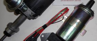
Design
The lock consists of mechanical and electrical parts. Briefly about the design of each of them:
- The mechanical part is a cylindrical mechanism, which can only be turned with a key designed specifically for it. In addition, this includes an anti-theft latch that prevents the steering wheel from turning.
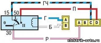
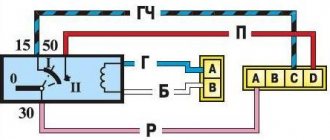
- The electrical part consists of terminals and contacts that close accordingly with each turn of the key. For this purpose, it is connected to the lock mechanics. There are only three contacts. One of them, the thirtieth, is supplied with plus directly from the battery. The remaining two (15 and 50) are intended to turn on consumers and the starter, respectively. To limit the current through the fiftieth contact, a relay is included in its circuit. The starter is powered through its contacts, and not through the Kalina ignition switch.
The immobilizer antenna is located in the decorative ring covering the 3Z. It responds to the transponder of the key inserted into the lock. The immobilizer recognizes only its own unique signal and gives permission to the control unit to start the engine.
Let's sum it up
The ignition switch in the LADA Kalina model is sufficiently reliable and is not capable of causing any problems to the owner. However, in rare cases it needs to be dismantled for repairs or replacement procedures. You can do this yourself, for which you need to stock up on the previously designated list of tools. Now you know how to replace and also how to remove the lock if any faults are present.
The ignition switch on any car, including the Lada Kalina, is a unit that allows you to start the engine by turning the key. Failure of this mechanism will lead to the impossibility of driving the car, so if malfunctions are detected in its operation, it is necessary to determine the cause as quickly as possible and make repairs. Read more about replacing the unit below.
ZZ malfunctions
Most often, damage to the Kalina ignition switch is associated with its mechanical part. In this case, it is impossible to turn the key to the desired position. A malfunction does not arise, as they say, out of the blue. As a rule, frequent jamming of the key is observed over the course of several months, which is eliminated by rocking it in the cylinder.
Rarely, there are cases of failure of the electrical component of the Lada-Kalina ignition switch. Basically they come down to a lack of contact when turned on. This is typical only for locks with a long service life. True, there is another common reason for burnt contacts - the car owner himself.
When installing additional equipment, the owner of the car does not take into account that the maximum permissible load on contact is 15, only 19 amperes. This is quite enough for regular consumers, but the lock can no longer withstand additional light and sound devices, especially those installed at home. The contacts begin to spark and eventually fail. Therefore, when installing additional equipment, it is necessary to use an additional relay to power it.
Ignition switch malfunctions
Like any electronic device, the ignition switch of the Lada Kalina is subject to frequent breakdowns. Malfunctions can occur for a variety of reasons, the most common of which are the following.
- Oxidation of contacts always leads to serious damage (usually due to moisture and dampness in the machine)
- Contact burnout , which occurs due to sudden voltage surges. Voltage drops usually occur when the power unit is started, during which the temperature inside the system rises sharply, causing the insulation to simply burn out. This is why it is so important to approach the launch issue wisely.
- Mechanical damage . If, when you are about to turn the key, you notice that it has become more difficult to do so than usual, it means that something happened to the lock cylinder, perhaps it was simply clogged with dirt or dust, or maybe there was a defect at the factory that came to light only now.
Symptoms of a problem
The main symptoms of 3D damage are most often obvious:
- The Kalina ignition key does not turn. You should not think that it can only jam in the “0” position. Sometimes, on the contrary, the car cannot be turned off because the key does not return to the neutral position.
- A number of devices do not work, including the indicator lamps on the panel do not light up.
- The starter does not turn.
- There are constant interruptions in movement, with the disappearance of readings from control devices.
- The instrument panel lamps light up after several turns of turning the key in one direction or the other.
As with any problem, some symptoms do not necessarily point to a lock. Therefore, before disassembling it, you need to exclude all other options. This can often be done based on indirect evidence. For example, if the starter does not rotate, but when you turn the key to position “2”, the relay clicks, then the lock is working.
Method for checking the ignition switch
You can check the operation of the ignition switch. You will need a multimeter for this. First you need to prepare the car for the test. To do this, disconnect the wire terminal from the negative terminal of the battery. Then the decorative lining of the steering column is removed. Next, the ignition switch wires are disconnected. Then, using a multimeter, the serviceability of the terminals in the block is checked. The key is in position 0 - off. Then you need to check the closure of the contacts in position 1 - on and 2 - starter. If there is a malfunction in the ignition switch, it needs to be replaced.
Repair or buy a new one
There is no clear answer to this question. The fact is that it is very difficult to find a new contact group on the Kalina ZZ, in contrast to the classics, Samara and the tenth family. Therefore, you have to repair it, which without experience, skills and desire is not the best idea. Most often, owners install a new ZZ by purchasing it assembled.
In this case, it is necessary to take into account that the Kalina ignition switch has an immobilizer that will not respond to the new key and the car will not be able to start. Of course there is a way out. You can retrain the immobilizer for a new key. In this case, you will also have to change the cylinders on the door locks.
You can do it easier - carry two keys with you. True, it is not clear whether it is worth keeping them on one bundle. Therefore, the most reasonable thing would be to make a new “tip” and install it on the old key. By the way, it may be included in the delivery of a new lock.
Preparing for installation and installing the ignition switch
First, we remove it in such a way that we disconnect the ignition switch wiring harness blocks. The chisel blade rests against the edge of the head of one of the bolts, then the bolt is loosened by striking the chisel. In the same way, loosen the three remaining bolts securing the switch. It is important that the chisel does not cut the bolt head. The chisel should turn the bolt counterclockwise to loosen it. Next, remove the bolts using narrow-nose pliers. The last bolt must be removed while holding the ignition switch. The lock fastening bracket and the lock itself are removed.
Next comes the installation of the ignition switch. Before this, you need to insert the key into it and turn it to the on position so that the latch of the steering shaft locking mechanism is pushed into the lock body. Now we install the ignition switch. remove the key from the ignition switch and check the operation of the steering shaft locking mechanism. Now we make sure that everything works and connect the ignition switch wire blocks and install the steering column pads.
Replacing the ignition switch
As always, if the work involves electricity, you need to start by disconnecting the negative terminal of the battery. The tool you will need is a shaped screwdriver and a small chisel. You must purchase an ignition switch in advance. In this case, you need to take into account the presence of an immobilizer. If everything is ready, you can proceed to replacement. The sequence of actions is as follows:
- After unscrewing the five bolts, remove the decorative steering column cover. The screws are different, so it’s better to remember which one was placed where. In addition, to remove the casing, you need to lower the steering column adjustment knob.
- The ignition switch is secured to two clamps, secured with bolts that cannot be unscrewed with a key. Therefore, you will have to use a chisel. You need to rest it against the cap and unscrew it with careful but rather strong blows until it becomes possible to do it with your hands. That is, you should not cut off the bolt with a chisel, but use it as an analogue of a key.
- Thus, you will have to unscrew all 4 screws.
- The lock will remain hanging on the wires.
- We disconnect the electrical connectors, and the ignition switch can be easily removed.
- Installation is carried out in reverse order.
It is worth noting that this sequence of actions is similar for all modifications of the car, including the ignition switch of the Kalina 2, produced since 2013.
How to replace the ignition switch on a VAZ 1117-VAZ 1119?
Note! Before you start changing the lock, disconnect the negative terminal from the battery, you still have to work with electronics! (For information on how to remove the terminal, see the article: “Replacing the battery on a VAZ”, in paragraph 1)
Removal: 1) At the beginning of the operation, you will need to remove the casing from the steering column, to do this, use a screwdriver and use it to remove the seven screws that secure the casing (see photo 1), after all the screws have been unscrewed, fully pull out the handle by which the steering wheel is adjusted (see photo 2, it is indicated by an arrow) and then remove the lower casing, and then lifting the upper one, also remove it from the steering column.
Note! When you remove the lower and upper casings, look at the side of them or look under the pedals for the rubber o-ring that is needed to seal the ignition switch from dust and dirt!
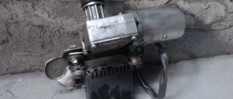
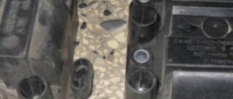
2) Then you will need to look at the lock itself and pay special attention to the wires that come from it, Kalina also has an immobilizer in addition, so there will be a lot of wires coming from the lock itself, and there will be only two wire connectors (One of the connectors will go to the starter is thus responsible for starting the car, and the second connector will go to the immobilizer and it is responsible for preventing the car from being stolen), so disconnect each connector from the pads (Each connector will be connected to the other two pads), to do this, grab your hand connector and simply disconnect it from the block using a little force (Do the same operation with the other connector).
Note! The photo above shows an example with an arrow where the wire connector coming from the ignition switch is connected to another block (This connector goes to the starter, the one that goes to the immobilizer looks a little smaller)!
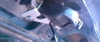
3) Next, as shown in the photo below, using a hammer and chisel, remove the four bolts (They have no edges and are indicated by arrows) that secure the lock to the steering column, how do you remove them, you ask? Let's explain! Take a chisel and a hammer in your hands and place the chisel on the edge of a bolt, then hit it and thereby try to move the bolt out of place, etc., until the bolts are completely turned out.
Note! If you don’t like this method, then you can also drill out these bolts, but only in this case, be careful not to damage anything!
4) When you have removed all four bolts, remove the bracket on one side of the steering shaft, which is indicated by the arrow, and on the other side, remove the ignition switch itself and put it aside if you no longer need it and you are going to put a new one in its place.
Note! In the event that you still suddenly need the old lock (For example, not all new locks are sold with a contact group, so you have to remove it from the old lock and install it on a new one), to remove the contact group from the lock, you must first be convinced that it’s not all about it, but about the lock and it needs to be replaced, for example, if you have problems with the electronics in the cabin, let’s say you turn the key and the devices don’t light up, then most likely it’s all in the contact group and the lock itself can’t be changed necessarily (But it’s not a fact that there may be a problem with the immobilizer, to do this, disassemble the contact group and check which contacts it has, oxidized or not), so here’s how to remove the contact group from the lock, for this:
1. Using a screwdriver or by hand, bend the lock that is located on the wire connector and then remove all the terminals together with the wires from this connector (see photo 1, but be sure to remember the location of each wire in the connector, although just below we described how you can install the wires into the connector without previously remembering their location, but it’s still better to remember so that problems do not arise in the future), then squeezing the latches of the contact group cover (see photo 2) remove it from the lock body itself (see photo 3) and then bending two plastic latches (see photo 4), separate the contact group cover and the contact group itself (see photo 5), and after the contact group itself is in your hands, remove the moving part from it and inspect all its contacts as shown in the sixth photo, if the contacts are found oxidized or burnt, then try cleaning them with fine-grained sandpaper, and if the contacts are severely damaged and cleaning them will not lead to anything, then in this case replace the contact group itself.
Note! When you reassemble the moving part of the contact group, install it so that the widest part that is present on it engages the protrusion on the cover as shown in the photo below:
Installation: The new lock is installed in the reverse order of removal and assembled the same way, but only during assembly there are some nuances, namely, when you install the terminals of the wires coming from the contact group into the wire connector, pay attention to the fact that each terminal must have its own position , so find the block of wires to which this connector will be connected and, looking at it, connect all the wires into the connector exactly in the same places where they go on the block, for example, on the block of wires you see that the red wire runs on the far left side, then, accordingly, do it on the wire connector in such a way that the same red wire can be connected to that wire, so that you can at least understand the situation a little lower, we posted a photo showing two terminals, and so the terminals and the wire connector will be exactly the same same terminals (there will be Males on the connector and females on the block) so try to combine them so that each color of the wire matches.
Note! When installing the lock, be sure to insert the key into it and turn it from the “0” position!
Replacing the lock return spring:
Note! This spring itself is easy to replace, but there is one But! It is not sold in stores, so you will need to either remove it from an old lock or make a homemade one, it looks like this:
1. At the beginning of the operation, in order to remove the spring, you will need to pick up the lock itself and unscrew the three bolts that secure the bracket to it. For an approximate location of these bolts, see the photo below, in which one of the screws is clearly visible .
2. When the bolts are all unscrewed, carefully remove the bracket and make sure that the ball located inside does not fall out (It is shown in the photo below), but if it falls out then put it in place, now let’s talk about the return spring, as you have already seen in the photo it is located in the cylinder of the lock itself and with its antennae it rests on the grooves that are in the cylinder, so using a screwdriver, remove the old one from there and install a new one in its place and assemble the entire mechanism in the reverse order of removal.
Additional video: For more information on how to replace the ignition switch, see the video below:
Pinout of the ignition switch VAZ-2101 - VAZ-2107
The ignition switch on these cars is located to the left of the steering column. It is fixed directly to it using two fixing bolts. The entire mechanism of the device, except for the upper part in which the keyhole is located, is hidden by a plastic casing.
On the visible part of the ignition switch housing, special marks are applied in a certain order, allowing inexperienced drivers to navigate the lock activation mode when the key is in the hole:
- “ ” – a mark indicating that all systems, devices and instruments that are turned on using the lock are turned off (this does not include the cigarette lighter, interior lighting, brake light, and in some cases the radio);
- “ I ” is a mark informing that the vehicle’s on-board network is powered from the battery. In this position, the key is fixed independently, and electricity is supplied to the ignition system, to the electric motors of the heater and windshield washer, instrumentation, headlights and light signaling;
- “ II ” – engine start mark. It indicates that voltage is applied to the starter. The key does not lock in this position. If you release it, it will return to the "I" position. This is done so as not to subject the starter to unnecessary loads;
- “ III ” – parking mark. If you remove the key from the ignition in this position, the steering column will be locked with a latch. It can only be unlocked by inserting the key back and turning it to position “0” or “I”.
The ignition switch has five contacts and, accordingly, five terminals, which are responsible for supplying voltage to the desired unit. All of them are numbered for convenience. Each pin corresponds to a wire of a certain color:
- “50” – output responsible for supplying current to the starter (red or purple wire);
- “15” – terminal through which voltage is supplied to the ignition system, to the electric motors of the heater, washer, and instrument panel (double blue wire with a black stripe);
- “30” and “30/1” – constant “plus” (pink and brown wires, respectively);
- “INT” – external lighting and light signaling (double black wire).
How to replace the ignition switch on a VAZ 1117-VAZ 1119?
Note! Before you start changing the lock, disconnect the negative terminal from the battery, you still have to work with electronics! (For information on how to remove the terminal, see the article: “Replacing the battery on a VAZ”, in paragraph 1)
Removal: 1) At the beginning of the operation, you will need to remove the casing from the steering column, to do this, use a screwdriver and use it to remove the seven screws that secure the casing (see photo 1), after all the screws have been unscrewed, fully pull out the handle by which the steering wheel is adjusted (see photo 2, it is indicated by an arrow) and then remove the lower casing, and then lifting the upper one, also remove it from the steering column.
Note! When you remove the lower and upper casings, look at the side of them or look under the pedals for the rubber o-ring that is needed to seal the ignition switch from dust and dirt!
2) Then you will need to look at the lock itself and pay special attention to the wires that come from it, Kalina also has an immobilizer in addition, so there will be a lot of wires coming from the lock itself, and there will be only two wire connectors (One of the connectors will go to the starter is thus responsible for starting the car, and the second connector will go to the immobilizer and it is responsible for preventing the car from being stolen), so disconnect each connector from the pads (Each connector will be connected to the other two pads), to do this, grab your hand connector and simply disconnect it from the block using a little force (Do the same operation with the other connector).
Note! The photo above shows an example with an arrow where the wire connector coming from the ignition switch is connected to another block (This connector goes to the starter, the one that goes to the immobilizer looks a little smaller)!
3) Next, as shown in the photo below, using a hammer and chisel, remove the four bolts (They have no edges and are indicated by arrows) that secure the lock to the steering column, how do you remove them, you ask? Let's explain! Take a chisel and a hammer in your hands and place the chisel on the edge of a bolt, then hit it and thereby try to move the bolt out of place, etc., until the bolts are completely turned out.
Note! If you don’t like this method, then you can also drill out these bolts, but only in this case, be careful not to damage anything!
4) When you have removed all four bolts, remove the bracket on one side of the steering shaft, which is indicated by the arrow, and on the other side, remove the ignition switch itself and put it aside if you no longer need it and you are going to put a new one in its place.
Note! In the event that you still suddenly need the old lock (For example, not all new locks are sold with a contact group, so you have to remove it from the old lock and install it on a new one), to remove the contact group from the lock, you must first be convinced that it’s not all about it, but about the lock and it needs to be replaced, for example, if you have problems with the electronics in the cabin, let’s say you turn the key and the devices don’t light up, then most likely it’s all in the contact group and the lock itself can’t be changed necessarily (But it’s not a fact that there may be a problem with the immobilizer, to do this, disassemble the contact group and check which contacts it has, oxidized or not), so here’s how to remove the contact group from the lock, for this:
1. Using a screwdriver or by hand, bend the lock that is located on the wire connector and then remove all the terminals together with the wires from this connector (see photo 1, but be sure to remember the location of each wire in the connector, although just below we described how you can install the wires into the connector without previously remembering their location, but it’s still better to remember so that problems do not arise in the future), then squeezing the latches of the contact group cover (see photo 2) remove it from the lock body itself (see photo 3) and then bending two plastic latches (see photo 4), separate the contact group cover and the contact group itself (see photo 5), and after the contact group itself is in your hands, remove the moving part from it and inspect all its contacts as shown in the sixth photo, if the contacts are found oxidized or burnt, then try cleaning them with fine-grained sandpaper, and if the contacts are severely damaged and cleaning them will not lead to anything, then in this case replace the contact group itself.
Note! When you reassemble the moving part of the contact group, install it so that the widest part that is present on it engages the protrusion on the cover as shown in the photo below:
Installation: The new lock is installed in the reverse order of removal and assembled the same way, but only during assembly there are some nuances, namely, when you install the terminals of the wires coming from the contact group into the wire connector, pay attention to the fact that each terminal must have its own position , so find the block of wires to which this connector will be connected and, looking at it, connect all the wires into the connector exactly in the same places where they go on the block, for example, on the block of wires you see that the red wire runs on the far left side, then, accordingly, do it on the wire connector in such a way that the same red wire can be connected to that wire, so that you can at least understand the situation a little lower, we posted a photo showing two terminals, and so the terminals and the wire connector will be exactly the same same terminals (there will be Males on the connector and females on the block) so try to combine them so that each color of the wire matches.
Note! When installing the lock, be sure to insert the key into it and turn it from the “0” position!
Replacing the lock return spring:
Note! This spring itself is easy to replace, but there is one But! It is not sold in stores, so you will need to either remove it from an old lock or make a homemade one, it looks like this:
1. At the beginning of the operation, in order to remove the spring, you will need to pick up the lock itself and unscrew the three bolts that secure the bracket to it. For an approximate location of these bolts, see the photo below, in which one of the screws is clearly visible .
2. When the bolts are all unscrewed, carefully remove the bracket and make sure that the ball located inside does not fall out (It is shown in the photo below), but if it falls out then put it in place, now let’s talk about the return spring, as you have already seen in the photo it is located in the cylinder of the lock itself and with its antennae it rests on the grooves that are in the cylinder, so using a screwdriver, remove the old one from there and install a new one in its place and assemble the entire mechanism in the reverse order of removal.
Additional video: For more information on how to replace the ignition switch, see the video below:
Pinout of lock VAZ-2108, VAZ-2109, VAZ-21099
Pinout according to the old type
Pinout of the VAZ-2109 ignition switch with unloading relay:
- comes +12V in position I, II, III (parking)
- comes +12V in position I, II, III (parking)
- comes +12V in position III (parking)
- position I, +12V goes out after turning on the ignition (contact 15/2), disappears at start (II);
- position I, +12V goes to the starter (pin 50);
- position I, +12V goes away after turning on the ignition (pin 15), does not disappear when starting II;
- +12V comes from the battery (pin 30);
- comes +12V constantly.
New pinout type
Pinout of the new VAZ-2109 ignition switch:
- comes +12V constantly
- comes +12V constantly
- +12V arrives after turning on the ignition (pin 15), does not disappear when starting II;
- +12V arrives after turning on the ignition (contact 15/2), disappears at start (II);
- position I, +12V goes to the starter (pin 50);
- +12V arrives after turning on the ignition (pin 15), does not disappear when starting II;
- +12V comes from the battery (pin 30);
- comes +12V constantly.
Pinout of lock VAZ-2110, VAZ-2111, VAZ-2112
Pinout of the ignition switch VAZ-2110:
- comes +12V for the microphone of the sensor of the inserted key;
- the mass comes when the driver's door is open;
- +12V goes to the starter (pin 50);
- +12V goes out after turning on the ignition (pin 15);
- +12V goes out when the key is inserted to pin 5 of the BSK;
- comes +12V to illuminate the lock cylinder;
- +12V comes from the battery (pin 30);
- not used.
Pinout of lock VAZ-2113, VAZ-2114, VAZ-2115
Pinout of the ignition switch VAZ-2113, 2114, 2115:
- comes +12V for the microphone of the sensor of the inserted key;
- the mass comes when the driver's door is open;
- +12V goes to the starter (pin 50);
- +12V goes out after turning on the ignition (pin 15);
- +12V goes out when the key is inserted to pin 5 of the BSK;
- comes +12V to illuminate the lock cylinder;
- +12V comes from the battery (pin 30);
- not used.
The structure of a car ignition switch
- Locking rod
- Frame
- Roller
- Contact disc
- Contact sleeve
- Block
- Protrusion of the contact part.
The lock mechanism is connected to many wires. They continue from the battery, connecting all the electrical devices of the car into a single chain. When you turn the ignition key, the electrical circuit is closed from the “-” terminal of the battery to the ignition coil. As a result, the current passes through the wires to the ignition switch, through its contacts it is directed to the induction coil, after which it returns back to the “+” terminal. As electricity passes through the coil, it generates high voltage, which it transmits to the spark plug. Therefore, the key closes the contacts of the ignition circuit, thereby starting the car engine.