10/15/2020 1,085 Alarms
Author: Victor
Do-it-yourself Tomahawk TW 9010 alarm installation begins with disconnecting all energy consumers and batteries. The terminal clamp with a negative signal must be disconnected from the latter to prevent a possible short circuit during the installation process.
[Hide]
Self-installation of Tomahawk TW 9010 alarm system
Before installing this model of security system yourself, it is recommended to check its functionality. Before installation, the Tomahawk 9010 alarm components must be connected to each other in one circuit, which is powered by a 12-volt power source. This will allow you to check the operation of the “alarm” before it is installed directly on the car.
Connection diagram and wire designations
Wiring diagram for connecting the main microprocessor module
When making connections to the main connector of an installed car alarm yourself, the user must be guided by the following data:
| Color | Purpose |
| Black | "Ground" or negative pole. It must be connected directly to the battery or to any standard bolt screwed into the body. It is important that it is fixed as firmly as possible. |
| Blue | Cable for connecting the interior lighting system. It is also possible to connect the contact to the window lift motor. When the protection is activated and disabled, the current on the line should be no more than 300 mA. |
| Red-black | Contact connecting to the ignition switch with output IGN3 |
| Yellow-black | Cable for connecting the starter lock relay |
| Red-yellow | Contact for implementing a second additional channel used to control electrical equipment |
| Black-gray | Output for connecting the tachometer cable or the engine fluid pressure controller in the lubrication system |
| Red-blue | Positive input for connecting door and hood sensors |
| White-orange | Negative output for door lock controllers |
| Violet | Contact for implementing the “Anti-robbery” option. The function should be turned on when a negative signal appears on the line. |
| Black-green | Power cable for side optics or light signaling. The circuit must be protected by a fuse device rated at 7.5 amps. |
| Yellow-green | A similar contact for connecting external lighting devices |
| Black and white | Programmable additional powertrain locking |
| Grey | Contact for connecting siren power supply |
| Blue-yellow | Cable for implementing a third additional channel or two-stage opening of door locks |
| Black and yellow | Contact for remote opening of the tailgate |
| Purple-orange | Wire for connecting to the parking brake lever sensor. If the car is equipped with a manual transmission, then the contact is connected to the negative signal of the handbrake. If you have an automatic transmission, the connection is made to the brake light circuit. |
| Black-blue and gray-orange | Contacts for connecting door and hood controller inputs |
One of the main nuances that must be taken into account when installing and connecting yourself is connecting the contacts on the autostart connector:
| Color | Purpose |
| Yellow-black | Contact for connection to the starter mechanism. This element must be connected to the output on the ignition switch, where a 12-volt voltage is generated when the key is turned to the “Starter” position. Used to start the power unit, it is necessary to make a connection in the area after the blocking relay. |
| Blue | Output pulse for auxiliary devices and equipment. It must be connected to the ignition switch contact, which generates a 12-volt voltage when the key is in the “ACC” mode. |
| Red (thin) | System power cable. Must be connected directly to the positive terminal of the battery. The electrical circuit must be protected by a 10 amp fuse device. |
| Red (thick) | Power supply contact for remote start power lines. It also needs to be connected directly to the battery. But this circuit must have a 40 amp fuse installed. |
| Yellow | Contact element IGN1. It must be connected to the ignition switch, to the output where a 12-volt voltage is generated when the key is switched to “ACC” mode. It is important that the load on the line does not disappear in the “Starter” position. |
| Green | Contact element IGN2. Must be connected to the contact on the lock, where voltage appears in the "ACC" mode and disappears in the "Starter" |
Selecting the location of the main blocks
Correctly determining the installation location of the component elements is necessary taking into account the design features of the car:
- The control module of the Tomahawk 9010 automotive system is installed in the vehicle interior, in the most hidden place and protected from external influences. It should be placed with the connector facing down to prevent liquid drops from running down the wires and moisture from getting inside. It is possible to install the device behind the instrument cluster; it must first be dismantled and turned off.
- In accordance with the Tomahawk 9010 operating manual, the siren is installed under the hood of the car. The wires from the device must be routed to the control unit in the passenger compartment; electrical circuits must not be accessible from under the bottom of the car. The siren should be placed in a hidden place, not exposed to elevated temperatures. If an autonomous device is used, then it is necessary to ensure free access to its well.
- Door triggers must be embedded in places protected from moisture. When these body parts are locked, the limit switches should not be accessible. Wiring from the devices is routed to the microprocessor.
- The shock and sensitivity controller is installed inside the car. Ideally, its installation should be done in the central part of the body. The device is fixed on a flat surface using glue or self-tapping screws.
- All high current lines must be protected with safety devices of a certain rating. Available in the form of a wire for connecting marker optics, power supply for alarm systems, and central locking.
The Tomahawk 9010 transceiver is located on the windshield, away from metal objects and electronic devices, as their presence will cause interference.
User DimASS showed the process of installing the Tomahawk 9010 car alarm using the example of a Nissan Tiida car.
Installing the hood opening sensor
When installing the Tomahawk TW 9010 alarm system with your own hands, you need to install the hood controller:
- At the end of the body element, a hole of the required diameter is drilled with a drill. It needs to be done in a place least exposed to moisture, where there is no drainage.
- The cable is being laid from the hood to the microprocessor. The wire is routed from the engine compartment into the passenger compartment through a special technological hole in the partition.
- The sensor is being installed on the hood. The free play of the limit switch rod must be at least 5 mm. After installation, the device is connected.
- Then all joints are fixed by soldering. The twisting method is not recommended because it is less reliable. If you have a multimeter, you can check the operation of the sensor with the hood open and locked.
Connecting the trunk sensor
Installing the trunk sensor is performed in the same way:
- The location where the controller will be located is marked on the tailgate. Using a drill, a technological hole for the sensor is drilled.
- The cable is being laid from the luggage compartment to the microprocessor. The gasket is made under the decorative lining of the interior. Do not place conductors in places where there are moving and rubbing body elements.
- The controller is installed on the tailgate. After installation, the free play of its rod is checked, which should be no more than 5 mm.
- The device is being connected. All connections are made using soldering. The contact points must be wrapped with electrical tape or heat-shrinkable tubing installed on the wire.
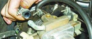
Connecting the central lock
To connect the central locking (CL), perform the following steps:
- The central locking control module is removed. This assembly is usually located on the back of the main fuse mounting block. To dismantle, you need to unscrew the bolts that secure the device, and then disconnect the wires from it.
- The contacts are soldered in accordance with the diagram. It is allowed to use backup door position outputs.
- Then the control module is connected and reinstalled using the central lock.
Setting up the shock sensor
It is necessary to configure the operation of the sensitivity controller using special adjustments located on the sensor. Initially, you need to bring the operating parameter of the device to the minimum value. The sensitivity is then gradually increased, and the user must check this value periodically. To do this, you need to lightly tap on the vehicle body.
Automatic engine start
Tomahawk TZ-9011 is a security system with feedback and automatic engine start
.
At the same time, it is very important to note the possibility of installing this alarm on vehicles with a Start-Stop
.
The system has three types
of engine starting: remote from the key fob and two automatic (hourly and temperature). At the same time, I would like to note that the system allows you to extend the operation of a remotely or automatically started engine an unlimited number of times.
The autostart function when installing this system can be implemented on vehicles with manual and automatic transmissions, including vehicles with a Start-Stop button.
How to connect an alarm without auto start
The absence of an automatic engine start function greatly simplifies the installation procedure of the anti-theft system. To connect, the user will need contact elements for the door position as well as the ignition switch.
Preparing the device
To prepare the system, perform the following steps:
- An additional relay and a safety device are installed in the ignition circuit.
- A microprocessor alarm control module is installed.
- The shock controller and transceiver are being installed.
- Pulses from the ignition switch and door positions are connected to the Tomahawk 9010 control module. The light signaling power lines are connected in parallel to the siren.
Working with ignition
If an ignition system blocking relay is used, then when connecting you need to use the electrical diagram:
Engine starting circuit using a blocking relay
Low current circuits and main connector
The installation of low-current power lines of the Tomahawk 9010 anti-theft system is carried out as follows:
- The power in the car turns off; to do this, you need to de-energize the battery.
- The main elements are connected to the microprocessor device. Available in the form of a transceiver with an antenna adapter, an LED, and a sensitivity controller.
- The contact elements of the hood and door sensors are connected to the main block of the control unit.
- The electrical circuits of the engine fluid temperature and pressure controller are connected to the instrument cluster. The contacts of the corresponding sensors are used for connection.
- After the connection is completed, all circuits are checked using the tester.
Reliable security for your car
We present to your attention the car alarm Tomahawk TZ-9011
.
This is a modern system, the main function of which is to ensure reliable protection of the vehicle from robbery and theft. In addition, installing this system will give you such an important service function as automatic engine start
.
Also, the Tomahawk TZ-9011 has a huge number of additional functionality and modes that cannot be ignored. This includes starting the engine by temperature and timer
.
remote trunk opening
.
automatic reset to security mode
.
control of central locking
when the engine is running, etc.
Vehicle search
modes .
hourly launch
.
safe driving
.
a turbo timer
and many others will ensure comfortable and fairly simple communication with the car.
How to program important options
Before using the anti-theft system, you must install a working battery in the communicator. The power supply is installed in a special compartment hidden behind the back cover. When installing, polarity must be taken into account. After removing the old battery and installing a new one, the user must press the button on the remote control with the open trunk indicator.
Key fob programming
Using all the functions of the Tomahawk 9010 car alarm is possible only after linking the communicator to the control unit.
The procedure for programming the key fob is as follows:
- The key is inserted into the ignition and turned to activate the ACC position. The car engine does not start.
- The button to enter the emergency maintenance mode “Override” is pressed and held for several seconds. You can release the key after the alarm siren sounds four beeps.
- Then the buttons on the key fob are pressed and held in the form of an open trunk and a crossed out speaker. A siren will sound to confirm the binding. If no programming action is taken within 6 seconds, the alarm will exit the menu.
The Molyarka channel clearly showed the process of linking the key fob to the Tomahawk 9010 alarm control unit.
Setting up autorun
Before setting up automatic engine start, the vehicle must be prepared:
- On a car with the engine running, the handbrake lever is raised.
- On the key fob, press a key with an indicator in the form of a key. An icon similar to smoke from an exhaust pipe will appear on the communicator screen. The remote control should also play a melodic signal.
- Subsequent actions must be completed within thirty seconds. The user removes the key from the ignition and opens the driver's door. The power unit must remain in a running state. Then the car owner must leave the car and lock all the doors. If the actions are performed correctly, the alarm will turn off the engine.
Feature settings nuances:
- Remote start by command is performed by pressing the key button on the key fob. After pressing it, an indicator should appear on the remote control display indicating a successful start. The power unit will operate for a certain time configured by the user. To increase the operating interval of the engine, the buttons with the key and the locked lock are “clicked” simultaneously. Each press increases the operating time by five minutes.
- To remotely stop the engine, the button with the key is clicked. If the power unit turns off, the parking lights of the car will blink four times. The communicator should play a melody, and the running engine icon will disappear from its display.
- To activate autostart based on temperature, the buttons with an indicator in the form of a key and an open trunk are pressed simultaneously. An indicator in the form of a thermometer will appear on the key fob screen, as well as a temperature level for starting. To disable this option, press similar buttons.