How to tension a chain on a Niva 21213 carburetor
Loosen nut 1 (Fig. 2-56) of the tensioner. In this case, rod 3 is released and the chain is tensioned by shoe 7 (Fig. 2-55), which is acted upon by spring 7 (Fig. 2-56).
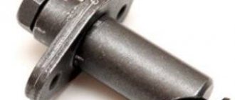
Rice. 2-56. Chain tensioner section:
1 - cap nut; 2 — tensioner body; 3 - rod; 4 — plunger spring; 5 — washer; 6 - plunger; 7 - spring; 8 - cracker; 9 — spring ring; A - plunger surface; B - places of punching at the end of the body.
Turn the crankshaft 1-1.5 turns in the direction of rotation. In this case, the tensioner spring acting on the shoe will automatically adjust the chain tension.
Tighten the nut 1 of the tensioner, due to which the rod 3 is clamped by the collets of the block 8, and when the engine is running, only the spring 4 acts on the plunger 6. This spring presses the plunger away from the head of the rod 3, and oil flows into the gap between them when the engine is running, playing the role of a shock absorber when shocks of the chain.
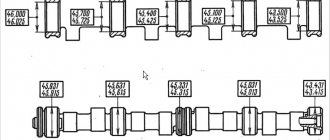
The timing chain plays an important role in the operation of the gas distribution mechanism. Over time, it stretches and requires tension, since the quality of the engine depends on it. Therefore, you need to know when to check the tension and how to tension the chain on a VAZ 2101. This topic is covered in an article and a video that demonstrates the process of checking and tensioning the chain drive.
When is stretching necessary?
Chain tensioning is required in the following cases:
- after engine repair;
- after replacing the product;
- when stretched after prolonged use.
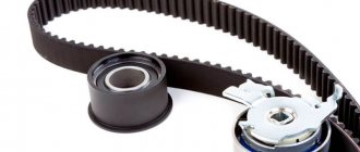
Timing belt VAZ 2101
In the first two cases, it is clear that checking the tension is necessary, since the chain was removed or replaced. In addition, you should also check that the alignment marks match. These marks are located on the crankshaft and camshaft. You can determine the need for tension by the sounds of the engine running. If the tension is weak, then during its operation extraneous noises are heard in the place where the chain drive is located. At the same time, timing parts wear out faster. Therefore, when checking the tension, it is necessary to pay attention to the condition of the damper and the shoe.
Timing tensioner shoe
If the tension is weak, the links can jump several teeth, then the valve timing will be disrupted. In this case, the car may stall, not start, and the speed will fluctuate. You can use a flathead screwdriver to check. It needs to be inserted and, using as a lever, pressed on the chain. It should not bend and be stretched like an arrow. Do not put too much pressure on the drive, although the part is metal, it is subject to deformation.
The video below looks at a VAZ 2101 car, in which a clattering sound is heard when the engine is running. It shows in detail how to check the condition of the damper, the shoe, and how to carry out tension.
Timing tags Niva carburetor
There is a standard 21213 NIVA, the engine of which has tractor traction at the bottom and lacks traction at speeds above 3000. Replacing the chain, all the sprockets, the camshaft with the bed did not solve the problem. Rearranging the chain on a tooth back and forth, too. It was noticed that the mark on the camshaft sprocket is not installed strictly opposite the protrusion; it can be placed half a tooth forward or backward. It was decided to check the valve timing. A device for adjusting valves with an indicator is welcome, but not at all required. However, I have it. The valve clearances must be properly adjusted!
When replacing the lower sprocket, check that the marks on the small sprocket and the pulley match. They correspond to TDC.
Having placed a mark on the pulley opposite the long mark 3 (TDC on the distributor drive cover), we mark marks 1 and 2 (5 and 10 degrees) on the pulley with a light marker (I used a white oil marker). We turn the crankshaft so that the standard mark on the pulley is opposite mark 1 (10 degrees) and mark 2 more marks - 5 and 10 degrees. on the other side of the zero mark. Also, by placing the extreme marks opposite the existing protrusions, we mark 15 and 20 degrees. We mark the zero mark on the second side of the pulley (now it is on both halves of the pulley). We have a scale marked on the crankshaft pulley - 20 - 15 -10 - 5 - 0 - 5 -10 - 15 -20 degrees. This is the easy way. You can make a scale out of paper, mark it more precisely, for example, with an accuracy of 1 degree, and stick it on the pulley. This method is a little more complicated, but also more accurate. I was quite happy with the 5 degree scale.
We install the crankshaft and camshaft according to the marks, as when adjusting the valves, the slider looks at the 4th cylinder. If there is an indicator, install it on the 2nd valve (intake of the 1st cylinder). We will use them to look for the moment of opening and closing of the valve. If there is no indicator, press the rocker up, using an open-end wrench 13-17. In this position, both valves of the 1st cylinder are clamped and slightly open (overlapping). Turn the crankshaft counterclockwise 10 -15 degrees. Using the applied marks, we find the moment when the intake valve begins to open by the appearance and disappearance of the gap between the rocker and the camshaft cam. We look at the pulley and the long mark on the cover, and count the degrees. For example, the mark is exactly between 10 and 15, we get 12.5 degrees. — the beginning of the opening of the intake valve. Let's remember. We move the indicator to the first valve (exhaust of the 1st cylinder) or control it by pulling the rocker up, turn the crankshaft clockwise, and find the moment when the exhaust valve closes.
Step-by-step instruction
Before starting troubleshooting, check that all timing components are free of mechanical defects. To do this, you need to remove the protective cover of the drive and perform a visual inspection of the parts: sprockets, damper, tensioner and shoe. If defects are found, these components should be replaced.
Tools
Before you start work, you need to prepare the necessary tools:
- keys to “13” and “38”;
- flat screwdriver;
- pliers.
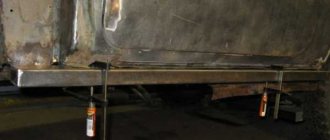
To carry out work, the car should be placed on a convenient platform and supports should be placed under the wheels so that it does not roll. The gear shift lever must be set to neutral.
Engine compartment of VAZ 2101
Stages
- First you need to find the tensioning device; it is located under the pipes near the pump. Use the key to “13” to release the tensioner. Once the chain is loosened, the shoe should pop off.
- Next, you should take the key at “38” and throw it on the crankshaft pulley nut. Then you need to turn the crankshaft a couple of turns in a clockwise direction.
- Rotate the shaft until the marks on the camshaft sprocket and on the camshaft bearing housing coincide. In this case, the spring located inside the tensioning device, acting on the shoe, will automatically perform the necessary tension.
- It is advisable to additionally check the tension using a screwdriver. If everything is normal, then we return to the tensioner and tighten its head with a wrench.
Checking the tension with a screwdriver
After tightening the chain drive, you should start the engine and check its operation. It should work without extraneous noise. If the noise remains after tensioning, then the reason may be in the damper. Then you need to check its serviceability and replace it if necessary. It may not be possible to tension the chain drive the first time, so this procedure will have to be repeated several times.
During the procedure, it is necessary to ensure that the marks match so that the valve timing does not go astray.
This operation should be carried out every time after any repair work. In addition, a preventive check should be performed after the 10 thousand kilometers mark. If you learn how to check and tension yourself, this will make it possible to extend its service life and save on car service costs.
How to adjust the ignition on a VAZ 21213
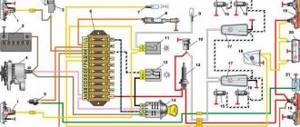
With the advent of various diagnostic devices on sale, it became possible to check the characteristics of regulators directly on the car. To check automatic regulators, you need to know their regulation ranges and characteristics (Fig.
7-21,166,191), which are usually presented in the form of diagrams (graphs) showing the change in the ignition timing angle depending on the crankshaft speed (CB regulator) and vacuum (vacuum regulator).
Before checking the regulators, the initial SOP is always checked.
To check the centrifugal regulator, you need a strobe light and a tachometer.
To ensure that the characteristics of the centrifugal regulator do not overlap with the characteristics of the vacuum regulator, the vacuum hoses are disconnected and plugged (the vacuum regulator is turned off).
The operation of the centrifugal regulator is checked at several characteristic points (usually four are enough). The control points are taken to be the values of the advance angles at the rotation speed: 1000, 1500, 2500 and 3000 rpm.
Apply white paint to 4 thin lines on the crankshaft pulley every 13 mm, which correspond to 10 degrees of crankshaft rotation. These marks should be located counterclockwise from mark 4.
Start the engine, point the strobe light at mark 3
. Increase the crankshaft speed in steps by 500 rpm. Determine the number of degrees of ignition timing using the crankshaft pulley with marks. Don't forget to subtract the initial SOP from this value. Compare the resulting characteristic of the centrifugal ignition timing regulator with the characteristic in Fig. which are below.
Unpretentiousness, ease of maintenance and maintainability are a well-known advantage of all carburetor engines that were installed on cars of the VAZ family, including the entire Niva model range.
But here also lies their main drawback, namely the need for periodic manual adjustments.
For example, after repairs or when changing the octane number of the fuel used, the driver is required to install the ignition on a VAZ Niva car (carburetor), while injection systems do not require such manipulations.
Installing the ignition on the Niva eliminates the problem of incorrect engine operation
Due to an incorrectly set ignition timing, the engine begins to operate incorrectly and its power decreases.
Timely adoption of measures to install the ignition on a VAZ-21213 Niva with a carburetor engine can eliminate the problem.
If you decide to make all the adjustments yourself, you can also save on the services of a specialist. To do this, you just need to read the guide below.
How to set up the ignition on a Niva yourself
The most accurate adjustment of the ignition 21213 (carburetor) can be performed using a strobe light. However, this is not the only method available in garage conditions, especially since many car enthusiasts do not have this device at their disposal and do not intend to buy it. Therefore, we will consider two ways to set the optimal ignition timing.
First, let's focus on adjustment using a strobe light. Prepare a “13” wrench and, in fact, the strobe itself for the upcoming work.
If everything is ready, you can begin to perform the adjustment operations, following the step-by-step instructions, but first we will make a reservation that for correct adjustment the engine must be warmed up and the carburetor must be properly adjusted. So, the procedure is as follows:
Read more: Renault Scenic 2 owner reviews petrol
To adjust the ignition correctly, the engine must be warmed up.
- First, using a special wrench to manually rotate the crankshaft, install the piston of the first cylinder so that it is at top dead center. To do this, follow the special marks that are located on the crankshaft pulley and on the timing cover. The location of the piston can be considered correct if the mark on the pulley is aligned with the middle mark on the cover.
- Next you need to remove the cover of the distributor sensor to determine whether the slider is positioned correctly. If it is directed towards the first cylinder, then the piston position corresponds to the compression stroke. If necessary, adjust the position of the slider by turning the crankshaft.
- Now you should check and, if necessary, set the optimal ignition moment of the combustible mixture - prepare a strobe light for this operation. To begin with, the device should be prepared for use by connecting its “negative” wire to the ground of the car, and the “plus” wire to the positive terminal of the battery. The sensor clamp should be connected to the high voltage contact designed to ignite the mixture in the first cylinder.
- Next, start the engine, setting the idle speed (approximately 800 rpm), and position the strobe so that its flashing beam is directed towards the mark on the crankshaft pulley. During operation, it should coincide with the middle mark on the timing cover. If alignment is ensured, then your vehicle has the correct advance angle, otherwise you will have to make an adjustment.
- With the engine running, use a wrench to loosen the sensor-distributor, then slowly turn it until the marks mentioned above match. If it is necessary to increase the angle, the distributor should be turned counterclockwise, and by turning it clockwise, you can ensure a decrease in the ignition timing. After completing the adjustment, be sure to tighten the mounting nuts.
Using a strobe, you can adjust the moment of ignition of the working mixture very accurately
This is exactly how the VAZ-21213 ignition (carburetor) is installed using a device such as a strobe. With its help, you can adjust the moment of ignition of the working mixture no worse than a qualified car service specialist. Next we will consider an option that does not require the use of this device.
How to set ignition timing using a light bulb
This adjustment method does not require the purchase of additional equipment and at the same time allows for fairly accurate adjustments.
If it suits you, then before you start adjusting the ignition of the VAZ-21213 (carburetor), prepare a 12 V test light by first soldering it to its contacts along the conductor.
And you will also need a “13” wrench and a wrench to manually rotate the crankshaft. During the setup process, follow the sequence of steps described below:
Adjusting the ignition timing according to the light bulb must be done with the engine turned off.
- Unlike the method that involves the use of a strobe, adjusting the ignition timing using a light bulb is carried out with the engine turned off. But here it is also necessary to install the piston of the first cylinder at TDC, aligning the mark on the pulley with the middle mark on the camshaft cover. Similar to the first method, remove the distributor cap and make sure that the slider is directed to the first cylinder.
- After loosening the distributor, connect the light bulb to ground and to the low-voltage wire of the ignition coil. Don't forget to reinstall the distributor cap.
- Next, turn on the car’s ignition (the light should light up at this moment) and slowly turn the sensor-distributor housing clockwise until the warning light turns off. As soon as this happens, slowly turn the distributor counterclockwise until the light goes out again. The advance angle set in this way will ensure stable engine operation at any speed.
- All that remains now is to tighten the nuts securing the sensor-distributor.
Read more: Button on Toyota automatic transmission
After adjustment work, it is necessary to check the operation of the Niva ignition system on the road
By the way, this method of setting the ignition is suitable for most domestic vehicles with a carburetor engine, including cars of the UAZ family.
After completing the adjustment work, it would be useful to check the operation of the ignition system of model 21213 on the road. To do this, accelerate the car to a speed of 50 km/h, engage fourth gear and press the accelerator pedal all the way.
If at this moment you hear quiet detonation sounds, it means that the moment of ignition of the working mixture is set correctly. The absence of sounds indicates late ignition, and if they are too loud, then the timing is too early.
In each of these two cases, you will have to re-configure.
This article describes the two most common ways to set the ignition timing, but they are not the only ones. For example, experienced craftsmen are able to make adjustments based on their own hearing.
However, this method is only available to those who thoroughly know how to set the ignition on the Niva 21213 (carburetor) and perform such work regularly.
For a simple car enthusiast, it will be enough to arm yourself with the above material to achieve a decent result.
It is clear to anyone, not even a car owner, that without the ignition the car will not start or drive (criminal options are not considered).
Depending on the car manufacturer, repairs or replacement of parts occur at a car service center or independently.
Installing the ignition on a VAZ 21213 NIVA carburetor is one of those processes that the owner can carry out himself. This approach will save money and give you personal experience in repairs.
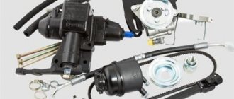
Features of replacing the ignition switch
First of all, it is important to make sure that the problem is in the lock. Therefore, the spark plugs, distributor and ignition coil are inspected. Often these parts of the internal combustion engine become the reason for failures of correct operation. If breakdowns in them are excluded, then the ignition switch (IZ) should be replaced. Removal order:
- Disconnect battery.
- Remove the steering column.
- Mark the wires going to the 3Z contact area. Using a flat-head screwdriver, unscrew the bolts securing the switch to the steering column (left and right).
- Insert the key into position 0. By pressing the screwdriver, press the lock slightly through the hole (do not touch the key).
- Lightly pull the 3Z towards you and dismantle it. The ignition switch Niva 21213 is switched off according to the wiring diagram (the contact part is changed if required). To do this, be sure to remove the retaining ring with a screwdriver.
- Remove the key, install the contact part so that the wide protrusions of the body and the parts coincide.
- The remaining parts are assembled in the reverse order.
Read more: What class does the Kia Rio belong to?
If you strictly follow the instructions and wiring diagram, no problems should arise. This is facilitated by the simplicity of the design. Moreover, the part can even be repaired if the damage is not critical.
Checking the quality of the ignition switch installation
It is logical that errors are possible when connecting contacts or incorrect installation of the lock itself. Therefore, it is necessary to test the protection in the installed state. You will need an ohmmeter and a voltmeter. Performance diagnostics:
- Checking the resistance between the terminals of the secondary winding: connect the probes to cylinders 1 and 4, then to cylinders 2 and 3. The data should approximately match. An error greater than 100 ohms indicates damage to the secondary winding.
- The wiring is checked with a voltmeter. The first control - one probe is placed on contact A, the second - on ground. Start the engine and record the data. Turn off the car and repeat the procedure with contact B. The readings should be about 12 volts.
- In addition, if there is no voltage, check the fuse, the possibility of broken wiring or corrosion of the contacts.
The last case is especially unpleasant, since you will have to check almost all the wiring, contact elements, etc. If there are possible suspicions about the electrical network, it is better to take the car to a professional auto electrician. Repairing it requires a thorough knowledge of the circuit and experience in finding defects.
Setting the ignition
The last step that a car enthusiast can perform in setting up the ignition system after installing the lock. You can take the car to a specialist, but this fairly simple procedure is unreasonably expensive. Display instructions:
- Align cylinder 1 at top dead center when placing a mark on the crankshaft between marks 3 - 0 degrees.
- Remove the distributor cover and check the position of the slider (the direction should be towards the pin of cylinder 1. Using a strobe light, set the torque and then connect the battery: ground to minus, positive contact to plus.
- The regulator clamp is connected to the high-voltage cable on cylinder 1. Mark the mark on the crankshaft pulley.
- Start the engine at speeds less than 800 rpm. Direct the strobe light at the mark on the pulley. If adjusted correctly, the mark should coincide with the middle one on the engine cover.
- If the marks do not match, turn off the engine and adjust the distributor mount clockwise or counterclockwise. Then repeat the procedure.
The final check takes place on the go. You will need to warm up the engine to 80 degrees. Then accelerate to 60 km/h (or go to 4th gear, as some experts advise). Press the gas pedal sharply. If the ignition is adjusted correctly, the engine may briefly detonate.
Source: https://dtp-avarii.ru/kak-otregulirovat-zazhiganie-na-vaz-21213/
How to tension a chain on a Niva 21213 carburetor
20 Niva VAZ 21213 chain tension adjustment
Adjusting chain tension GENERAL INFORMATION
Chain tensioner section
1 – cap nut; 2 – tensioner body; 3 – rod; 4 – plunger spring; 5 – washer; 6 – plunger; 7 – spring; 8 – cracker; 9 – spring ring; A – plunger surface; B – places of punching at the end of the body
Procedure 1. Loosen nut 1 of the tensioner. In this case, shaft 3 is released and the chain is tensioned by shoe 7 (see figure. Plan of the drive of the camshaft and auxiliary units), which is acted upon by spring 7. 2. Turn the crankshaft 1–1.5 turns in the direction of rotation. In this case, the tensioner spring acting on the shoe will automatically adjust the chain tension. 3. Tighten the tensioner nut 1, due to which the shaft 3 is clamped by the collets of the block 8, and when the engine is running, only the spring 4 acts on the plunger 6. This spring presses the plunger away from the head of the rod 3, and oil flows into the space between them when the engine is running, which plays a role shock absorber during chain impacts. Replacing the chain Procedure 1. To remove the chain, brake the vehicle with the parking brake, open the hood, remove the spare tire with its support pipe and remove the battery. 2. Remove the air filter and close the carburetor inlet neck with a technological plug. 3. Separate the air and throttle valve drive cables from the carburetor. 4. Drain the coolant from the radiator and cylinder block, remove the radiator with hoses and thermostat. 5. Remove the fan by unscrewing the fastening nuts. 6. Remove the cylinder head cover and turn the crankshaft until the mark on the camshaft sprocket aligns with the mark on the bearing housing (see figure. Checking the alignment of the installation mark on the camshaft sprocket with the mark on the bearing housing), and the marks on the generator drive pulley – with a long mark on the camshaft drive cover (see figure. Marks for setting ignition timing). 7. Unscrew the camshaft sprocket bolt. 8. Loosen the cap nut of the chain tensioner, press out the tensioner rod with a mounting blade and secure it with the cap nut. 9. Remove the camshaft sprocket. 10. Loosen the generator and remove its drive belt. 11. Engage 4th gear in the gearbox, unscrew the nut and remove the generator drive pulley from the crankshaft. 12. Remove the camshaft drive cover with the gasket by unscrewing the nuts securing the cover to the cylinder block and the bolts securing the oil sump to the cover. 13. Unscrew the limiting pin 6 (see figure. Layout of the camshaft drive and auxiliary units) and remove the camshaft drive chain. 14. Install the chain in the reverse order of removal, following the recommendations set out in subparagraph 2.4. 15. Lubricate the chain with engine oil before installation. 16. Install new gaskets under the camshaft drive cover and cylinder head cover. 17. After installing the chain, adjust the tension of the chain and generator drive belt, adjust the carburetor drive and ignition timing. Niva VAZ 21213 chain tension adjustment Next page»»»»»»
- 1.2.3.4.5.6.7.8.9.10.11.12.13.14.15.16.17.18.19.20.21. 22.23.24.25.26.27.28.29.30.31.32.33.34.35.36.37.38.39.40. 41.42.43.44.45.46.47.48.49.50.51.52.53.54.55.56.57.58.59.60. 61.62.63.64.65.66.67.68.69.70.71.72.73.74.75.76.77.78.79. 80.81.82.83.84.85.86.87.88.89.90.91.92.93.
Replacing timing chain and sprockets (injection engine)
Remove the cylinder head cover (see here).
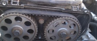
Rotate the crankshaft until the mark (hole) on the camshaft sprocket coincides with the mark on the camshaft bearing housing.
Remove the crankshaft pulley (see here). Disconnect the camshaft sprocket with the chain from the camshaft (see here). Remove the chain from the sprocket.
For clarity, we show the chain removal operations on a dismantled engine.
We unscrew the three bolts securing the oil pan to the camshaft drive cover (see here).
Using a 10mm socket, unscrew the three nuts and six bolts securing the camshaft drive cover to the cylinder block.
A “ground” wire is secured under one nut (on the left side).
Remove the camshaft drive cover.
. and a sealing gasket.
Using the “17” head, unscrew the axis of the hydraulic chain tensioner shoe.
We take out the tensioner shoe.
Remove the chain from the crankshaft sprockets and the oil pump drive shaft.
We take out the camshaft drive chain.
Using a puller, press the sprocket from the toe of the crankshaft.
The sprocket is fixed on the crankshaft with a segment key. To remove the key.
. Carefully, trying not to damage the key and shaft, use a chisel to knock it out of the groove of the crankshaft.
. and remove the key.
Using a chisel, loosen the bolt securing the oil pump drive shaft sprocket.
Using a 17mm spanner, unscrew the sprocket mounting bolt. We hold the sprocket from turning with a screwdriver resting through the hole in the sprocket on the head of the bolt securing the thrust flange of the roller.
. and the oil pump drive shaft sprocket.
Location of camshaft drive and oil pump parts.
Install the drive mechanism parts in reverse order. Having installed the key in the groove of the crankshaft, we put on the sprocket.
. and press it onto the crankshaft, tightening the pulley mounting nut with a wrench.
Having unscrewed the nut, we press the sprocket with a tool head of a suitable size (a piece of pipe).
Before installing the chain, align the mark (mark above the keyway) on the crankshaft sprocket with the mark (protrusion) on the cylinder block.
. and the mark on the camshaft sprocket with the mark on the shaft bearing housing.
Having installed the chain and hydraulic tensioner, turn the crankshaft clockwise two turns and check that the alignment marks match.
We install the removed parts in reverse order.
Replacing the chain tensioner VAZ 21213, VAZ 21214, VAZ 2131
Chain tensioner - as is already clear from its name, it is needed only to tension the chain so that it does not loosen while the engine is running, and so over time this part breaks for various reasons, this happens, sometimes the tensioner simply cannot withstand very heavy loads breaks, for example, if you keep the engine speed in the red zone for a long time, the tensioner cannot withstand and breaks, but it can also break because it is not very durable, for example, there are a lot of very bad tensioners on the market at the moment qualities that really fail very quickly and after that they will need to be replaced with a new one, and you will learn how to do this from this article.
Chain 21214, alternative
links coated with tin, rollers with Teflon
I have already mentioned that I work with ZMZ motors. There is a wonderful person in this area - Igor Aleksandrovich Medvedev. On the Internet and on forums, nickname Rhodes-M. I have joint projects with this person in other areas, so further information is “first-hand.” For ZMZ engines, he developed and brought to production several different gas distribution mechanisms. But we are interested in something else. These timing belts included unique single and double row chains. On forums and drive they can be found either as “platinum series” or “fast chains for ZMZ”. In the process of work, it turned out that there was a pilot batch for engines 21214. Since 2020, I began experiments and subsequent work on this spare part. I have departmental vehicles in service, the mileage of which is 120-130 thousand km per year, so full-scale tests are carried out quite quickly. Main design features and differences from Ditton:
- The design of the chain is bush-roller (similar to Ditton)
- The side links of the chain are coated with tin for break-in.
- Rollers coated with Teflon (wear resistance)
- Tensile strength is 10% higher than Ditton
- The back of the chain is polished. This gives us sliding and little wear on the tensioner shoe and damper
Where is the chain tensioner located?
It is located on the side of the engine, you can easily find it by the way if you approach the car from the right side of the engine compartment (The countdown starts from the back of the car to the front), there is also a battery installed nearby and there is a standard injection receiver in the form of curved pipes ( It is white), so when you stand on this very right side, look for the place indicated in the photo, this is the same tensioner.
When to change the chain tensioner
It changes only if it has become unusable, but how can you understand this, you ask? In general, when the tensioner becomes unusable, the car’s engine begins to run significantly louder, because the chain is weakened and thus there is such a roar as if you started the car with a diesel injection system, and not with a gasoline one, so if you hear something rattling in the engine, vibration may also appear, and by the way, this knocking should become less as the speed increases, that is, if the engine is noisy at idle and the chain rattles, then just give a little gas and if this knock goes away (the higher the speed, the weaker it should be knocking) then it is most likely really the tensioner, although many other parts could be to blame for this, but first you need to check it, since it is removed very quickly and is also checked accordingly.
An interesting article about biofuels produced from ordinary sawdust, read more here.
How to replace the chain tensioner on a VAZ 21213-VAZ 2131
Cars of the Niva family are very old models, in my opinion the very first cars went back to 1977 if memory serves, but these are new times and the car is still being produced and refined, so here are the chain tensioners that AvtoVAZ installed on its cars in Depending on the year of production, they may differ from each other, so for example, somewhere before 2000 or even higher, these cars of the Niva family came with the most common spring chain tensioners, these tensioners are very easy to remove, but one of their drawbacks (Or maybe an advantage) is the fact that they do not tension themselves, that is, from time to time you have to tighten them yourself, which is very inconvenient, but this is for someone, because it only takes 1-2 minutes to tighten the chain tensioner!
Theory
A very common opinion is that the timing mechanism on engine 21213 is almost “eternal”. But let's define two important concepts. A working unit and a correctly functioning unit. The design of the Fiat of 66-67 of the last century is, of course, ingenious in its simplicity and margin of reliability, but still time takes its toll: the chain begins to play and “stretch,” the springs in the tensioner weaken and, as a result, the ignition begins to “float.” Each design has both its pros and cons. Yes, a double-row chain is quite “breakable”, but to keep it taut it requires more force than a single-row chain. This means the tensioner must have a “fresh” spring.
Chain tensioner 21213, options
I will give three workable options that I know of and that I took directly from the manufacturers. These are ORIGINAL designs. Everything else that is on the market is clones and fakes of these spare parts.
Chain tensioner 21213, “isai”
The photo shows its “sibling”, a tensioner for the ZMZ engine, but the meaning does not change. The operating principle is a clock spring. When the chain slacks, the spring unwinds; when there are shock loads, the spring can collapse. The advantage of this design is its originality and ease of operation. The downside is the price at the moment and the chain tension. On double-row chains, this effect is “almost not terrible”, so you can safely use this spare part. We “talked” with the product designer on this topic, but as soon as the dispute turned to the personalities of the disputants, I ended our conversation.
Chain tensioner 21213, “Rusmash”
The operating principle is a toothed rack, a calibrated spring and a ratchet tooth. A very simple design, time-tested. Made at a RUSSIAN factory, stable quality. Cons: an amazing amount of fakes on Rusmash tensioners, both for VAZ and ZMZ engines. Moreover, there are fakes of two stripes, “imitating the original” and simply cloning a design under any other brand. But since I work directly with the plant, this minus is not important to me.
Chain tensioner 21213, “TZA”
This tensioner was installed starting with “kopecks”, and since then its design has not changed. The principle of operation is a rod, a powerful spring and a collet clamp of the rod. The disadvantage of the design is that the old generation of “carburetor engineers” has passed away, and the “injector engineers” do not know how to use and install it correctly. In order for everything to fall into place, I turned to the Fiat manual for AvtoTAZ on assembling and tuning the 2101 engine. In short: you set the timing belt according to the marks, shot off the tensioner, cranked the crankshaft a couple of times manually, warmed up the engine to operating temperature on the XO and without turning off the engine, tightened the collet. This way your chain is in IDEAL tension until the next maintenance work. Next time this procedure can be performed when changing the oil. It was on the basis of this tensioner that I made my design for timing belt 21214.
Mechanical chain tensioner. Main manufacturers.
The photo shows three main options common in Russia. The first product is made by the people and on the forums of the ANC “auto pilot”. The second product is manufactured by Rusmash, usually called the pilot. The third tensioner belongs to the designer Isaev, colloquially Isay. My team and I personally have installed several dozen of each type of tensioner on cars, so I have the right to talk about statistics and operating features. Something from behind the scenes. The first two tensioners belong to the pen of one person. Designer Igor Medvedev. On motor forums under the nickname Rhodes-M. As far as I know, patents for these inventions or utility models are registered in his personal name. I work together with this person on other projects, so the information about the designs and manufacturing features is first-hand.
Autopilot. Principle of operation. Rack. Of the three, this is the undisputed leader. I have not noticed any shortcomings in operation. Cars with mileage of more than 150 thousand have already arrived where I installed autopilots from the very first batches. It is very convenient to work when replacing the camshaft; it does not need to be removed from the cylinder head. Flaw. It is difficult to find an “original” that has passed quality control. Medvedev left and the quality of input immediately dropped greatly. The cost of production has become cheaper.
Pilot. The operating principle is a toothed rack. Good quality tensioner. The big brother of "autopilot". Stable quality. It is also possible to work without removing it from the cylinder head. The main disadvantage is the huge percentage of fakes on the market. This tensioner was the first successful design, and the Chinese grabbed it. If Autopilot is completely impossible to find, then Pilot is very difficult to find “original”. Based on the St. Petersburg market, I estimate the prevalence of counterfeits for this tensioner at 70%. I work with Rusmash directly, so this as a “minus” is insignificant.
Installation
Installing tensioners in a carburetor engine is much simpler than in an injection engine. In principle, you don’t even need to remove the valve cover; the double-row chain will not go anywhere and will not jump out anywhere. But after installation, it is imperative to make a couple of timing revolutions so that the tensioner selects the total chain clearance. What I recommend paying attention to: the stroke of tensioners 21213 is less than the stroke of 21214, but this is not a minus, but a plus, from the point of view of chain control. Once the tensioner has completely selected its operating range, there is no need to weld anything onto it. This is a signal that the chain has “stretched”. Next, replace the chain, tensioner shoe and damper. High-quality double-row sprockets usually survive 2-3 chain changes. I anticipate the answer to the question that will be asked: which tensioner do you recommend installing? Of these three, I like TZA the most. Firstly, because Fiat)). Secondly, the most gentle work in relation to the chain. But this only applies to timing belt 21213.
Sources:
https://litezona.ru/kak-natjanut-cep-na-nive-21213-karbjurator/ https://avtorial.ru/VAZ2/Niva2121_20.html https://www.vazzz.ru/kak-na-vaz -2121-natyanut-tsep-zamena-natyazhitelya-tsepi-kogda-nuzhno-menyat/ https://auto.kombat.com.ua/regulirovka-natyazheniya-czepi-privoda-raspredelitelnogo-vala-vaz-21213-lada-niva / https://niva-fr.ru/natyazhitel-tsepi-dlya-21213/
Features of self-removal of the defect that has arisen
When replacing the hydraulic chain tensioner and installing a mechanical tensioner on a Chevrolet, the valve cover must be removed.
Next, after pulling out the pin, you need to use a ratchet wrench to make one full revolution of the crankshaft. It is important to pay attention to whether the slack chain on the Niva has come out of the grooves of the tensioner shoe and damper. If this point is ignored and the defect is not eliminated, then the consequences can be sad (but this only applies to a single-row chain).
Also, as a result of the first revolution, the primary slack of the chain on the Niva is selected and, as a rule, the rod immediately comes out one or two more clicks, relative to the first shooting. After self-replacement, subsequently no extraneous sounds will be observed during startup on the Chevrolet Niva. The engine will always run smoothly.
By the way, practice shows that sometimes you don’t have to resort to replacing the unit described above on a Chevrolet, but simply get by with just changing the oil. Many auto mechanics advise using semi-synthetic oil rather than synthetic oil.
When the hydraulic tensioner is replaced, nothing will rattle when you start the engine. Since it is always only the faulty element that rattles. The instructions for replacing this unit yourself prove that the procedure is not at all complicated, and in addition, the price of the issue is no more than 2,000 rubles. But there is one “but” - if the Niva Chevrolet car is relatively new and was under warranty, it will automatically be canceled.